2A9FO-MD-091PMulti-function Emergency Radio With LCD Screen
ZHUHAI MEDING TECHNOLOGY CO.,LTD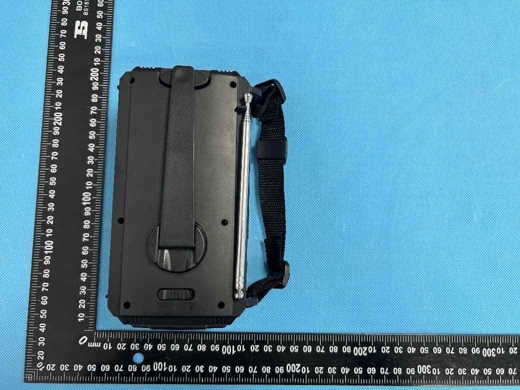
Click to zoom
Application Details
- Equipment Class
- CXX - Communications Rcvr for use w/ licensed Tx and CBs
- Date of Grant
- Aug 07, 2024
- Application Purpose
- Original Equipment
- Date of Application
- Aug 07, 2024
- Equipment Note
- Multi-function Emergency Radio With LCD Screen
- Frequency Range
- 87.00000000 - 108.00000000
- Country
- China
Documents & Files
Document Text
Text extracted from the exhibit documents filed with the FCC. Open a document above to read the original.
Users Manual
User manual Multi-function Emergency Radio With LCD Screen CONTENTS: RADIO OPERATION WEATHER ALERT SOS ALARM READING LAMP FLASHLIGHT 3 POWER METHODS BATTERY PROTECTION POWER THE DEVICE EARHONE JACK CARE AND MAINTENANCE SPECIFICATION WARRANTY PACKING LIST -1--2--3- RADIO OPERATION WEATHER ALERT B HAND CRANK POWER PACKING LIST WARRANTY SPECIFICATION CARE AND MAINTENANCE EARPHONE JACK POWER THE DEVICE SOS ALARM FLASHLIGHT Antenna Hand crank handle The radio can also be charged by turning the handle at the back of the device. The device has a full 12-month warranty against manu- facturing defects from the date of purchase. Insert the 3.5mm Earphone jack to listen to the radio to enjoy your leisure time. The charging indicator light will light red when the handle is being turned. Connect the USB device to the USB output port of the unit via USB cable to power the USB device. When the device is used as a power bank (discharge), the power indicator lights will diminish. This feature is suggested to use in emergency, do not use it as a normal power bank. Radio x 1 USB-C Cable x 1 Frequency range Dimensions Weight Power consumption Working voltage Power source Waterproof level Power input LED flashlight Power of flashlight Power of reading lamp 175x80x98mm 570g 7w 2.4~4.2V 10000mAh / 3.7V IPX3 USB-C 5V 2A 200LM(Max) 2W 1.2W Long press the SOS button for 3s to activate the loud siren and the flashing far beam Press the SOS button again to turn it off. -7--8--9--10- For the first use or when the unit idles over 60 days, please hand crank for 1 minutes to activate the internal battery. The device shall not be exposed to dripping or splashing,and objects filled with liquids should no tbe placed on the device. Please do not over discharge the unit, so as not to reduce the internal battery life, or even damage the battery. Avoid flashlight light directly into the eyes, or it will hurt the eyes. User Manual x 1 Gift box x 1 Made in China Power switch Flashlight button Output ports Input port Earphone jack 3 POWER METHODS BATTERY PROTECTION READING LAMP -4- A USB CHARGING The waterproof cover on the side of this product has 2 USB output ports , a USB input port and a earphone jack. Connect the supplied USB-C cable to the USB Input port on the unit's right side to charge the built-in lithium battery. Meanwhile, the red charging indicator light will light up. Please have the radio charged at least once every three months. Turn on the radio by pressing the power button, press it again to turn it off. Press the left or right buttons to navigate between radio stations.Adjust the volume by pressing the volume buttons. The green LED will light up when the radio has found a stable reception/channel.Extend the antenna and adjust the direction to get better signal. The blue LED will light up when the batteries are being used Note: Please turn on the power switch(on the back side) to "ON" before using each function. When the radio is on, press “WX AL” button to switch to weather alert mode. Once receives bad weather infor- mation, "ALERT" will flash on the screen and the device will alarm. Press button “WX AL” or “BAND” to exit weather alert mode. -5- Rotate the rocker clockwise or counterclockwise, and keep it at a constant speed of 130 rpm for 1 minute, which can be used for far beam or dipped beam for 10 minutes or radio work for 5-6 minutes. -6- C SOLAR POWER Place the unit in clear sunlight to let it charge as efficiently as possible. The charging indicator will turn red when charging. The charging effect depends on the intensity of the sunlight. Stronger sunlight give better effect. It is mostly used for maintaining the battery, to prolong the battery life. This emergency radio is designed with a feature of shutdown in low voltage. To protect the chip, the power supply will be cut off to protect the battery from damage when there is an overload or a short circuit in this unit. It will cut of the power source when the voltage is lower than 2.7V and protects the battery from being over-disacharged and damaged. If you press the SOS button at this time, you will hear the SOS alarm in the earphone. It will return to the radio function when you turn off the SOS function. Open the solar panel, the reading lamp lights up, and close the solar panel it will light off. The first press on the flashlight button, the far beam lights up. The second press on the flashlight button, the dipped beam lights up. The third press with both far and dipped beam light up. The forth press with both light off. FM 87~108MHz AM 520~1710KHz WB/ALERT: 1: 162.400 MHz 2: 162.425 MHz 3: 162.450 MHz 4: 162.475 MHz 5: 162.500 MHz 6: 162.525 MHz 7: 162.550 MHz Flashlight Button Flashlight Power ON/OFF Alert Power on Indicator Tuning Band Selector VOL +/- Speaker SOS Alarm LCD Display Solar Panel Charging Indicator Signal Indicator FCC Warning This device complies with Part 15 of the FCC Rules. Operation is subject to the following two conditions: (1) This device may not cause harmful interference, and (2) this device must accept any interference received, including interference that may cause undesired operation. Note: This equipment has been tested and found to comply with the limits for a Class B digital device, pursuant to part 15 of the FCC Rules. These limits are designed to provide reasonable protection against harmful interference in a residential installation. This equipment generates, uses and can radiate radio frequency energy and, if not installed and used in accordance with the instructions, may cause harmful interference to radio communications. However, there is no guarantee that interference will not occur in a particular installation. If this equipment does cause harmful interference to radio or television reception, which can be determined by turning the equipment off and on, the user is encouraged to try to correct the interference by one or more of the following measures: —Reorient or relocate the receiving antenna. —Increase t…
Text truncated - open the document above for the full version.
External Photos
Reference No.: WTX24X07178901WPage 2 of 10 Waltek Testing Group (Shenzhen) Co., Ltd. Http://www.waltek.com.cn EXHIBIT 2 - EUT EXTERNAL PHOTOGRAPHS EUT View 1 EUT View 2 Reference No.: WTX24X07178901WPage 3 of 10 Waltek Testing Group (Shenzhen) Co., Ltd. Http://www.waltek.com.cn EUT View 3 EUT View 4 Reference No.: WTX24X07178901WPage 4 of 10 Waltek Testing Group (Shenzhen) Co., Ltd. Http://www.waltek.com.cn EUT View 5 EUT View 6 Reference No.: WTX24X07178901WPage 5 of 10 Waltek Testing Group (Shenzhen) Co., Ltd. Http://www.waltek.com.cn EUT View 7
ID Label/Location Info
ReferenceNo.:WTX24X07178901WPage1of10 WaltekTestingGroup(Shenzhen)Co.,Ltd. Http://www.waltek.com.cn ANNEX EXHIBIT1-PRODUCTLABELING ProposedFCCIDLabelFormat FCCID:2A9FO-MD-091P Thisdevicecomplieswithpart15oftheFCCRules. Operationissubjecttothefollowingtwoconditions: (1)Thisdevicemaynotcauseharmfulinterference,and (2)thisdevicemustacceptanyinterferencereceived, includinginterferencethatmaycauseundesired operation. Specifications:Thelabelshallbesecurelyaffixedtoapermanentlyattachedpartofthedevice,inalocation whereitisvisibleoreasilyaccessibletotheuser,andshallnotbereadilydetachable.Thelabelshallbe sufficientlydurabletoremainfullylegibleandintactonthedeviceinallnormalconditionsofusethroughout thedevice’sexpectedlifetime. ProposedLabelLocationonEUT FCCIDLabel Location
Internal Photos
ReferenceNo.:WTX24X07178901WPage6of10 WaltekTestingGroup(Shenzhen)Co.,Ltd. Http://www.waltek.com.cn EXHIBIT3-EUTINTERNALPHOTOGRAPHS EUTHousingand BoardView1 Solder Board-Component View1 ReferenceNo.:WTX24X07178901WPage7of10 WaltekTestingGroup(Shenzhen)Co.,Ltd. Http://www.waltek.com.cn Solder Board-Component View2 Solder Board-Component View3 ReferenceNo.:WTX24X07178901WPage8of10 WaltekTestingGroup(Shenzhen)Co.,Ltd. Http://www.waltek.com.cn Solder Board-Component View4
Test Report
WaltekTestingGroup(Shenzhen)Co.,Ltd. Http://www.waltek.com.cnPage 1 of 22 TESTREPORT ReferenceNo.......................:WTX24X07178901W FCCID....................................:2A9FO-MD-091P Applicant...............................:ZHUHAIMEDINGTECHNOLOGYCO.,LTD Address.................................: Floor2,Building6A,ZHIZAODAJIE,JINHEROAD,HONGQITOWN,JINWAN DISTRICT,ZHUHAI,GUANGDONG,China Manufacturer........................:ThesameasApplicant Address.................................:ThesameasApplicant ProductName......................:Multi-functionEmergencyRadioWithLCDScreen ModelNo...............................:MD-091P Standards..............................:FCCPART15SUBPARTB DateofReceiptsample.....:2024-07-30 DateofTest...........................:2024-07-30to2024-08-01 DateofIssue........................:2024-08-01 TestReportFormNo.......... : WTX_FCCPART15B_001 TestResult............................:Pass Remarks: Theresultsshowninthistestreportreferonlytothesample(s)tested,thistestreportcannotbe reproduced,exceptinfull,withoutpriorwrittenpermissionofthecompany.Thereportwouldbeinvalidwithout specificstampoftestinstituteandthesignaturesofapprover. PreparedBy: WaltekTestingGroup(Shenzhen)Co.,Ltd. Address:1/F.,Room101,Building1,HongweiIndustrialPark,Liuxian2ndRoad, Block70Bao'anDistrict,Shenzhen,Guangdong,China Tel.:+86-755-33663308Fax.:+86-755-33663309Email:[email protected] Testedby:Approvedby: DashanChenJasonSu ReferenceNo.:WTX24X07178901W WaltekTestingGroup(Shenzhen)Co.,Ltd. Http://www.waltek.com.cnPage2of22 TABLEOFCONTENTS 1.GENERALINFORMATION.......................................................................................................................................4 1.1PRODUCTDESCRIPTIONFOREQUIPMENTUNDERTEST(EUT).................................................................................4 1.2TESTSTANDARDS.......................................................................................................................................................5 1.3TESTMETHODOLOGY.................................................................................................................................................5 1.4TESTFACILITY...........................................................................................................................................................5 1.5EUTSETUPANDOPERATIONMODE..........................................................................................................................6 1.6MEASUREMENTUNCERTAINTY..................................................................................................................................7 1.7TESTEQUIPMENTLISTANDDETAILS........................................................................................................................8 2.SUMMARYOFTESTRESULTS.............................................................................................................................10 3.CONDUCTEDEMISSIONS.......................................................................................................................................11 3.1TESTPROCEDURE.....................................................................................................................................................11 3.2BASICTESTSETUPBLOCKDIAGRAM......................................................................................................................11 3.3ENVIRONMENTALCONDITIONS................................................................................................................................11 3.4SUMMARYOFTESTRESULTS...................................................................................................................................11 4.RADIATEDEMISSION.............................................................................................................................................14 4.1TESTPROCEDURE.....................................................................................................................................................14 4.2BLOCKDIAGRAMOFTESTSETUP............................................................................................................................14 4.3TESTRECEIVERSETUP.............................................................................................................................................14 4.4CORRECTEDAMPLITUDE&MARGINCALCULATION...............................................................................................15 4.5ENVIRONMENTALCONDITIONS................................................................................................................................15 4.6SUMMARYOFTESTRESULTS...................................................................................................................................15 APPENDIXPHOTOGRAPHS.......................................................................................................................................22 ReferenceNo.:WTX24X07178901W WaltekTestingGroup(Shenzhen)Co.,Ltd. Http://www.waltek.com.cnPage3of22 Reportversion VersionNo.DateofissueDescription Rev.002024-08-01Original /// ReferenceNo.:WTX24X07178901W WaltekTestingGroup(Shenzhen)Co.,Ltd. Http://www.waltek.com.cnPage4of22 1.GENERALINFORMATION 1.1ProductDescriptionforEquipmentUnderTest(EUT) GeneralDescriptionofEUT ProductName:Multi-functionEmergencyRadioWithLCDScreen TradeName:/ ModelNo.:MD-091P AddingModel(s):/ Note:Thetestdataisgatheredfromaproductionsample,providedbythemanufacturer. TechnicalCharacteristicsofEUT RatedVoltage:USBDC5V;BatteryDC3.7V RatedCurrent:/ RatedPower:/ BatteryCapacity:10000mAh LowestInternalFrequency:/ HighestInternalFrequency:108MHz ClassificationofITE:ClassB ReferenceNo.:WTX24X07178901W WaltekTestingGroup(Shenzhen)Co.,Ltd. Http://www.waltek.com.cnPage5of22 1.2TestStandards Thetestswereperformedaccordingtofollowingstandards: FCCRulesPart15SubpartB:UnintentionalRadiators. ANSIC63.4-2014:AmericanNation…
Text truncated - open the document above for the full version.
Test Setup Photos
ReferenceNo.:WTX24X07178901WPage9of10 WaltekTestingGroup(Shenzhen)Co.,Ltd. Http://www.waltek.com.cn EXHIBIT4-TESTSETUPPHOTOGRAPHS ConductedEmission TestSetup RadiationEmission View(Below1GHz) ReferenceNo.:WTX24X07178901WPage10of10 WaltekTestingGroup(Shenzhen)Co.,Ltd. Http://www.waltek.com.cn RadiationEmission View(Above1GHz) *****ENDOFREPORT*****
Contact Information
Applicant
Lu Dong(Engineering assistan)
Test Firm
Waltek Testing Group (Shenzhen) Co., Ltd.Jandy So
Technical Specifications
| # | Rule Parts | Frequency Range | Power Output |
|---|---|---|---|
| 2 | 15B | 87 MHz - 108 MHz | - |
Other Applications from ZHUHAI MEDING TECHNOLOGY CO.,LTD
2A9FO-CD86
Jan 16, 2026Desktop CD Player
Equipment Class
DTS - Digital Transmission System
2A9FO-R12
Jul 22, 2024Portable outdoor Radio
Equipment Class
DSS - Part 15 Spread Spectrum Transmitter
2A9FOMD-R11
Oct 30, 2023Portable Outdoor Radio
Equipment Class
DSS - Part 15 Spread Spectrum Transmitter
2A9FO-MD319
Nov 17, 2022Weather Alert Radio
Equipment Class
CXX - Communications Rcvr for use w/ licensed Tx and CBs