2A9UU-PRXDMAXP-BASE-X3SE
Axtel sp. z o.o. sp. k.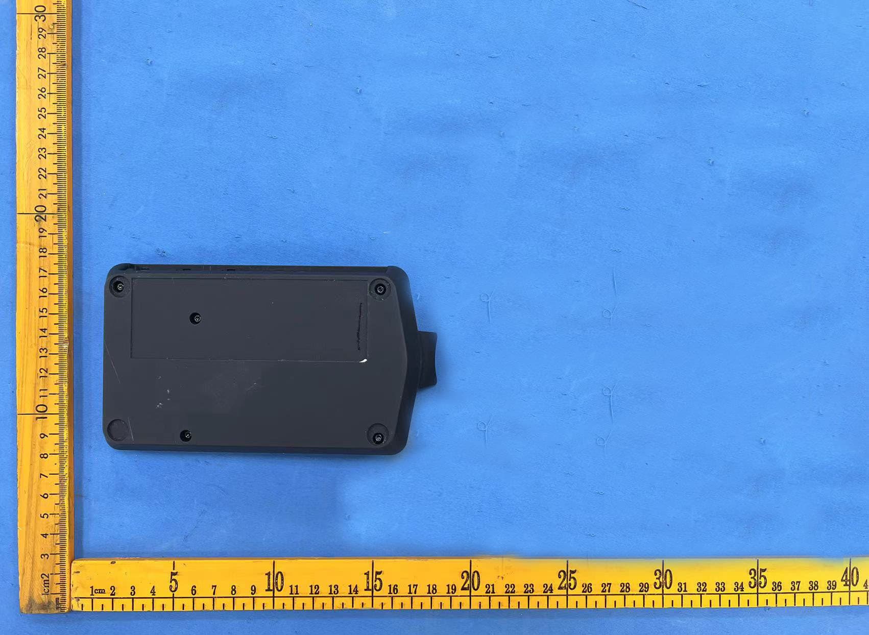
Click to zoom
Application Details
- Equipment Class
- JAB - Part 15 Class B Digital Device
- Date of Grant
- May 30, 2023
- Application Purpose
- Original Equipment
- Date of Application
- May 30, 2023
- Equipment Note
- AXP-BASE-X3SE
- Company
- Axtel sp. z o.o. sp. k.
- Country
- Poland
Documents & Files
Document Text
Text extracted from the exhibit documents filed with the FCC. Open a document above to read the original.
Users Manual
PL www.axtelworld.com NEW GENERATION OF PROFESSIONAL HEADSETS INSTRUKCJA OBSŁUGI INSTRUCTION MANUAL PL EN Axtel Prime X3 Duo Headset Axtel Prime X3 Duo Base www.axtelworld.com2 Welcome to the world of Axtel. The product is co-financed from EU funds, project number: POIR.03.02.01-0016/18-00 Made in the EU EN 3 CONTENTS 1. Contents of the package 4 2. Product description 5 2.1 Description of the headset 5 2.2 Description of the base station 6 3. First start-up 7 3.1. Connecting the device 7 3.2 Activating the headset 7 3.3 Turning off the headset and the base 7 3.4 Pairing – connecting a new headset to the base 7 4. Headset setup 7 4.1 Connecting to a desk phone 7 4.2 Connecting to a computer 9 4.3 Connecting to a mobile phone 9 5. Use 9 5.1 Answering and ending calls 9 5.2 Desk phone 10 5.3 Call managing 10 5.4 Adjusting the volume for each channel separately 10 5.5 Muting the microphone 10 5.6 Loss of signal and connection with the base 11 5.7 Hearing protection adjustment 11 5. 8 Headset and base localizer 11 5.9 Listening-in on the channel: 11 Computer and Mobile Phone (Bluetooth ® ) 5.10 Information about battery status 11 and active channel 5.11 Resetting the headset 12 6. Voice messages 12 7. Recommendations 13 8. Declarations and warnings 13 9. Headset parameters 14 10. Accessories 15 www.axtelworld.com4 1. Contents of the package Binaural headset Wireless DECT headset with advanced noise cancellation DECT Base station Headset base for charging and call control 12 V power supply Region-specific power supply version MicroUSB/USB-A cable USB connection cable, connecting the base station to a computer Picture 1 Figure 3 Figure 5 Picture 2 Base station RJ9/RJ9 cable (PN AXP-XRJ) Specially designed connection cable compatible with most desk phone models available on the market. Figure 4 EN 5 2. Product description 2.1 Description of the headset Binaural (DECT) headset with a microphone: Flexible and adjustable headband – allows for proper adjustment to the shape of your head MFB – multifunction button for switching on and off, answering calls and switching between channels Dock connector – for charging and communication with the base Microphone mute (MUTE) – turn on and off by pressing both +/- volume control buttons simultaneously Figure 6 Volume up button (+) – increases the volume Volume down button (-) – lowers the volume Reset button Adjustable microphone arm www.axtelworld.com6 BA S E STATI ON 2.2 Description of the base station 4 buttons on the base Docking port for the headset – charging – pairing 1234 MicroUSB socket connecting to a computer Power supply socket 12 V connecting to the power supply RJ9 socket connecting the headset to a desk phone Buttons for the adjustment of microphone sensitivity RJ9 socket connecting a desk phone RJ45 socket socket for remote reception (EHS) FIgure 7FIgure 8 The base station enables the connection of 3 communication channels (Desk phone , Computer and Mobile phone) and makes it possible to handle calls (answering, ending, switching, putting on hold ). 1. The Desk Phone button activates the desk phone transmission channel 2. The Computer button activates the computer/laptop transmis - sion channel. 3. The Mobile Phone button activates the mobile phone Blue - tooth ® transmission channel. 4. The Microphone Mute (MUTE) button mutes and unmutes the microphone. EN 7 3. First start-up 3.1. Connecting the device Connect the base station to a power source using the power adapter included in the package. Correct connection is indicated by an acous - tic signal from the base. 3.2 Activating the headset There are two ways to start the headset: a) Press the MFB button for about 1 second. When the device turned on, a sound will play from the headset. b) By placing the headset on the base station socket. Correct start-up and pairing of the headset with the base will be indi - cated by an acoustic signal, and the MFB will stop flashing. 3.3 Turning off the headset and the base To turn off the headset, press the MFB for 5 seconds. A sound signal in the headset indicates that it has been turned off. To turn off the base, disconnect the power cable. 3.4 Pairing – connecting a new headset to the base Put an enabled headset on an enabled base, then press the Desk phone button . This action is going to begin the process of pairing the headset. Headset delivered along with the whole set does not require pairing. 4. Headset setup 4.1 Connecting to a desk phone (see Figure 9 and 10) There are three distinct ways to connect your Prime X3 to a desk phone a) Connecting to a desk phone equipped with a dedicated headset port. b) Connecting to a deskphone that does not have a dedicated headset port. c) Optional connection via EHS cable. Note: Some phones require a different cable with an appropriate plug dedicated to the particular phone model (e.g. Jack 2.5 mm, Jack 3.5 mm, RJ45). In this case you need to buy the right cable (section 10. Accessories). https://axtelworld.com/headsets/compatibility/ * The Prime X3 is not to be connected simultaneously to the headset and handset socket in the desk phone. www.axtelworld.com8 a) Connecting to a desk phone equipped with a dedicated headset port. Connect the Prime X3 with a desk phone by plugging in one end of the supplied AXP-XRJ connection cable to the dedicated headset port in the desk phone , and the other one into the desk phone socket in the base. (see Figure 9a) b) Connecting to a desk phone that does not have a headset port. Plug the Axtel Prime X3 headset into the desk phone handset port. To do it, unplug the desk phone handset from the desk phone, then plug it into the handset socket in the base. Connect the base station to the desk phone with the provided AXP-XRJ cable – one end into the handset socket in the desk phone and the other into the desk phone socket in the base. (see Figure 9b) c) Optional connection to the mechanical hook switch lifter the corre- sponding socket on the base (see figure 10) Receiving calls…
Text truncated - open the document above for the full version.
Attestation Statements
U.S. AGENT LETTER OF ATTESTATION Date: 2023-05-10 FEDERAL COMMUNICATIONS COMMISSION Authorization and Evaluation Division 7435 Oakland Mills Road Columbia, MD 21046 Ref: Attestation Statements CFR 47 §2.911(d)(7) Filing FCC ID: 2A9UU-PRXDM Axtel sp. z o.o. sp. k. (“the Applicant”) certifies that, as of the date of the filing of the application, Shop4Tele Inc is our designated U.S. agent for service of process for the above referenced FCC ID. Axtel sp. z o.o. sp. k. (“the Applicant”) accepts to maintain an agent for no less than one year after the grantee has terminated all marketing and importation or the conclusion of any Commission-related proceeding involving the equipment. Shop4Tele Inc accepts, as of the date of the filing of the application, the obligation of the designated U.S. agent for service of process for the above referenced FCC ID. Designated U.S. Agent Information: Name: Shop4Tele Inc Address: 35440 Mound Rd, Sterling Heights, MI 48310 FRN: 0033687617 Tel.: 888-282-8878 Email: [email protected] Signed by (printed name): Garri Sahakian Signature: Applicant: Axtel sp. z o.o. sp. k. Address: FRN: 0033218983 Tel: 482-24909713 Email: [email protected] Signed by (printed name): Mr Mikolaj Kubiak Signature: Woloska 16 st. Warsaw Poland 02-675
External Photos
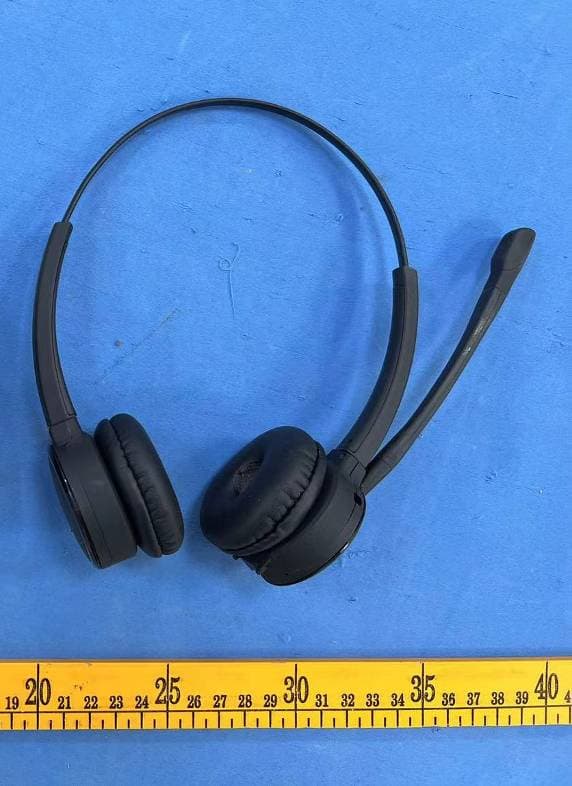
Shenzhen Accurate Technology Co., Ltd. Project No.: RA221116-54358E-EM External Photos Page 1 of 4 External Photos Shenzhen Accurate Technology Co., Ltd. Project No.: RA221116-54358E-EM External Photos Page 2 of 4 Shenzhen Accurate Technology Co., Ltd. Project No.: RA221116-54358E-EM External Photos Page 3 of 4 Shenzhen Accurate Technology Co., Ltd. Project No.: RA221116-54358E-EM External Photos Page 4 of 4
ID Label/Location Info
Shenzhen Accurate Technology Co., Ltd. Report No.: RA221116-54358E-EM EXHIBITA-FCC ID LABEL AND LOCATION FCC ID Label FCC ID Label Location Information The label shown shall be permanently affixed at a conspicuous location on the device and be readily visible to the time purchase (Labeling requirements per 2.295)
Internal Photos
Shenzhen Accurate Technology Co., Ltd. Project No.: RA221116-54358E-EM Internal Photos Page 1 of 5 Internal Photos Shenzhen Accurate Technology Co., Ltd. Project No.: RA221116-54358E-EM Internal Photos Page 2 of 5 Shenzhen Accurate Technology Co., Ltd. Project No.: RA221116-54358E-EM Internal Photos Page 3 of 5 DECT Module (FCC ID: Y82-SC14S) Shenzhen Accurate Technology Co., Ltd. Project No.: RA221116-54358E-EM Internal Photos Page 4 of 5 BT Module (FCC ID: A8TBM62S2) Shenzhen Accurate Technology Co., Ltd. Project No.: RA221116-54358E-EM Internal Photos Page 5 of 5
RF Exposure Info
Note: This report may contain data that are not covered by the A2LA accreditation and are marked with an asterisk “★”. Shenzhen Accurate Technology Co., Ltd. is not responsible for the authenticity of any test data provided by the applicant. Data included from the applicant that may affect test results are marked with an asterisk ’*’. Customer model name, addresses, names, trademarks etc. are not considered data. This report cannot be reproduced except in full, without prior written approval of the Company. Unless otherwise stated the results shown in this test report refer only to the sample(s) tested. This report is valid only with a valid digital signature. The digital signature may be available only under the Adobe software above version 7.0. Shenzhen Accurate Technology Co., Ltd. 1/F., Building A, Changyuan New Material Port, Science & Industry Park, Nanshan District, Shenzhen, Guangdong, P.R. China Tel: +86 755-26503290 Fax: +86 755-26503290 Web: www.atc-lab.com Version 47: 2023- 01-30 Page 1 of 5 FCC-MPE TEST REPORT Applicant Name : Axtel sp. z o.o. sp. k. Address : Woloska 16 st. Warsaw Poland 02-675 Report Number : RA221116-54358E-MPE FCC ID: 2A9UU-PRXDM Test Standard (s) FCC PART 1.1307 and FCC Part 2.1091 Sample Description Product Type: AXP-BASE-X3SE Model No.: Axtel Prime X3 Duo Base Trade Mark: Axtel Date Received: 2022-12-12 Report Date: 2023-04-10 Test Result: Pass* * In the configuration tested, the EUT complied with the standards above. Prepared and Checked By: Approved By: Lipa Wu Candy Li EMC Engineer EMC Engineer Shenzhen Accurate Technology Co., Ltd. Report No.: RA221116-54358E-MPE Version 47: 2023-01-30 Page 2 of 5 FCC-MPE TABLE OF CONTENTS DOCUMENT REVISION HISTORY ......................................................................................................................... 3 FCC §1.1307 & §2.1091- RF EXPOSURE................................................................................................................... 4 TEST RESULT: .............................................................................................................................................................. 5 Shenzhen Accurate Technology Co., Ltd. Report No.: RA221116-54358E-MPE Version 47: 2023-01-30 Page 3 of 5 FCC-MPE DOCUMENT REVISION HISTORY Revision Number Report Number Description of Revision Date of Revision 0 RA221116-54358E-MPE Original Report 2023-04-10 Shenzhen Accurate Technology Co., Ltd. Report No.: RA221116-54358E-MPE Version 47: 2023-01-30 Page 4 of 5 FCC-MPE FCC §1.1307 & §2.1091- RF EXPOSURE Applicable Standard According to KDB 447498 D04 Interim General RF Exposure Guidance v01, clause 2.1.4 –MPE-Based Exemption: An alternative to the SAR-based exemption is provided in § 1.1307(b)(3)(i)(C), for a much wider frequency range, from 300 kHz to 100 GHz, applicable for separation distances greater or equal to λ/2π, where λ is the free-space operating wavelength in meters. The MPE-based test exemption condition is in terms of ERP, defined as the product of the maximum antenna gain and the delivered maximum time-averaged power. For this case, a RF source is an RF exempt device if its ERP (watts) is no more than a frequency-dependent value, as detailed tabular form in Appendix B. These limits have been derived based on the basic specifications on Maximum Permissible Exposure (MPE) considered for the FCC rules in § 1.1310(e)(1). Table to § 1.1307(b)(3)(i)(C) - Single RF Sources Subject to Routine Environmental Evaluation f = frequency in MHz; R = minimum separation distance from the body of a nearby person (appropriate units, e.g., m); For multiple RF sources: Multiple RF sources are exempt if: in the case of fixed RF sources operating in the same time-averaging period, or of multiple mobile or portable RF sources within a device operating in the same time averaging period, if the sum of the fractional contributions to the applicable thresholds is less than or equal to 1 as indicated in the following equation. Where: a = number of fixed, mobile, or portable RF sources claiming exemption using paragraph (b)(3)(i)(B) of this section for Pth, including existing exempt transmitters and those being added. b = number of fixed, mobile, or portable RF sources claiming exemption using paragraph (b)(3)(i)(C) of this section for Threshold ERP, including existing exempt transmitters and those being added. c = number of existing fixed, mobile, or portable RF sources with known evaluation for the specified minimum distance including existing evaluated transmitters. P i = the available maximum time-averaged power or the ERP, whichever is greater, for fixed, mobile, or portable RF source i at a distance between 0.5 cm and 40 cm (inclusive). P th,i = the exemption threshold power (P th ) according to paragraph (b)(3)(i)(B) of this section for fixed, mobile, or portable RF source i. ERP j = the ERP of fixed, mobile, or portable RF source j. Shenzhen Accurate Technology Co., Ltd. Report No.: RA221116-54358E-MPE Version 47: 2023-01-30 Page 5 of 5 FCC-MPE ERP th,j = exemption threshold ERP for fixed, mobile, or portable RF source j, at a distance of at least λ/2π according to the applicable formula of paragraph (b)(3)(i)(C) of this section. Evaluated k = the maximum reported SAR or MPE of fixed, mobile, or portable RF source k either in the device or at the transmitter site from an existing evaluation at the location of exposure. Exposure Limit k = either the general population/uncontrolled maximum permissible exposure (MPE) or specific absorption rate (SAR) limit for each fixed, mobile, or portable RF source k, as applicable from § 1.1310 of this chapter. Test Result: For worst case: Mode Frequency Range (MHz) Output Power* Antenna Gain* ERP Evaluation Distance (cm) ERP Limit (mW) (dBm) (mW) (dBi) (dBd) (dBm) (mW) BT 2402-2480 5.53 3.57 1.927 -0.223 5.307 3.39 20 768 BLE 2402-2480 4.4 2.75 1.927 -0.223 4.177 2.62 20 768 DECT 1921.536-1928.448 20.0 100 -3.5 -5.65 14.35 27.23 20…
Text truncated - open the document above for the full version.
Test Report
Note: This report may contain data that are not covered by the A2LA accreditation and are marked with an asterisk “★”. Shenzhen Accurate Technology Co., Ltd. is not responsible for the authenticity of any test data provided by the applicant. Data included from the applicant that may affect test results are marked with an asterisk ’*’. Customer model name, addresses, names, trademarks etc. are not considered data. This report cannot be reproduced except in full, without prior written approval of the Company. Unless otherwise stated the results shown in this test report refer only to the sample(s) tested. This report is valid only with a valid digital signature. The digital signature may be available only under the Adobe software above version 7.0. S henzhen Accurate Technology Co., Ltd. 1/F., Building A, Changyuan New Material Port, Science & Industry Park, Nanshan District, Shenzhen, Guangdong, P.R. China Tel: +86 755-26503290 Fax: +86 755-26503290 Web: www.atc-lab.com V ersion 18: 2023-01-30 Page 1 of 38 FCC-E MC TEST REPORT Applicant Name : Axtel sp. z o.o. sp. k. Address : Woloska 16 st. Warsaw Poland 02-675 R eport Number : RA221116-54358E-EM FCC ID: 2A9UU-PRXDM Te s t St a n d a r d ( s ) FCC PART 15B Sample Description Product Type: AXP-BASE-X3SE Model No.: Axtel Prime X3 Duo Base Tr a d e M a r k : A x t e l Date Received: 2022-12-12 Date of Test: 2023-04-07 Report Date: 2023-04-10 Te s t Re s u l t : Pass* * In the configuration tested, the EUT complied with the standards above. Prepared and Checked By: Approved By: Lip a Wu Candy Li EMC Engineer EMC Engineer Shenzhen Accurate Technology Co., Ltd. Report No.: RA221116-54358E-EM Version 18: 2023-01-30 Page 2 of 38 FCC-EMC TABLE OF CONTENTS DOCUMENT REVISION HISTORY ......................................................................................................................... 3 GENERAL INFORMATION ....................................................................................................................................... 4 PRODUCT DESCRIPTION FOR EQUIPMENT UNDER TEST (EUT) ..................................................................................... 4 OBJECTIVE ................................................................................................................................................................... 4 TEST METHODOLOGY .................................................................................................................................................. 4 MEASUREMENT UNCERTAINTY .................................................................................................................................... 5 TEST FACILITY ............................................................................................................................................................. 5 SYSTEM TEST CONFIGURATION .......................................................................................................................... 6 JUSTIFICATION ............................................................................................................................................................. 6 EUT EXERCISE SOFTWARE .......................................................................................................................................... 6 SPECIAL ACCESSORIES ................................................................................................................................................. 6 EQUIPMENT MODIFICATIONS ....................................................................................................................................... 6 SUPPORT EQUIPMENT LIST AND DETAILS .................................................................................................................... 6 BLOCK DIAGRAM OF RADIATED TEST SETUP ............................................................................................................... 7 SUMMARY OF TEST RESULTS ............................................................................................................................... 9 TEST EQUIPMENT LIST ......................................................................................................................................... 10 FCC §15.107 – CONDUCTED EMISSIONS ............................................................................................................ 11 APPLICABLE STANDARD ............................................................................................................................................ 11 EUT SETUP ................................................................................................................................................................ 11 EMI TEST RECEIVER SETUP ....................................................................................................................................... 11 TEST PROCEDURE ...................................................................................................................................................... 12 FACTOR & OVER LIMIT CALCULATION ...................................................................................................................... 12 TEST DATA ................................................................................................................................................................ 12 FCC §15.109 - RADIATED EMISSIONS ................................................................................................................. 21 APPLICABLE STANDARD ............................................................................................................................................ 21 EUT SETUP ................................................................................................................................................................ 21 EMI TEST RECEIVER & SPECTRUM ANALYZER SETUP ......................................…
Text truncated - open the document above for the full version.
Test Setup Photos
Shenzhen Accurate Technology Co., Ltd. Project No.: RA221116-54358E-EM Test Photos Page 1 of 4 Test Mode 1 Photo of Power Line Conducted Emission Measurement Shenzhen Accurate Technology Co., Ltd. Project No.: RA221116-54358E-EM Test Photos Page 2 of 4 Radiated Emissions Test View (Below 1GHz) Radiated Emissions Test View (Above 1GHz) Shenzhen Accurate Technology Co., Ltd. Project No.: RA221116-54358E-EM Test Photos Page 3 of 4 Test Mode 2&3&4 Photo of Power Line Conducted Emission Measurement Shenzhen Accurate Technology Co., Ltd. Project No.: RA221116-54358E-EM Test Photos Page 4 of 4 Radiated Emissions Test View (Below 1GHz) Radiated Emissions Test View (Above 1GHz)
Contact Information
Applicant
Mikolaj Kubiak
Test Firm
Shenzhen Accurate Technology Co., Ltd.Lisa Zhang
[email protected]+86-755-26503290
Technical Specifications
| # | Rule Parts | Frequency Range | Power Output |
|---|---|---|---|
| 1 | 15B | - | - |
Other Applications from Axtel sp. z o.o. sp. k.
2A9UU-PRXHDM
May 30, 2023AXP-PRXDSE
Equipment Class
PUE - Part 15 Unlicensed PCS portable Tx held to ear