2A9WD-RS3ELECTRIC SCOOTER
Riley Scooters Ltd.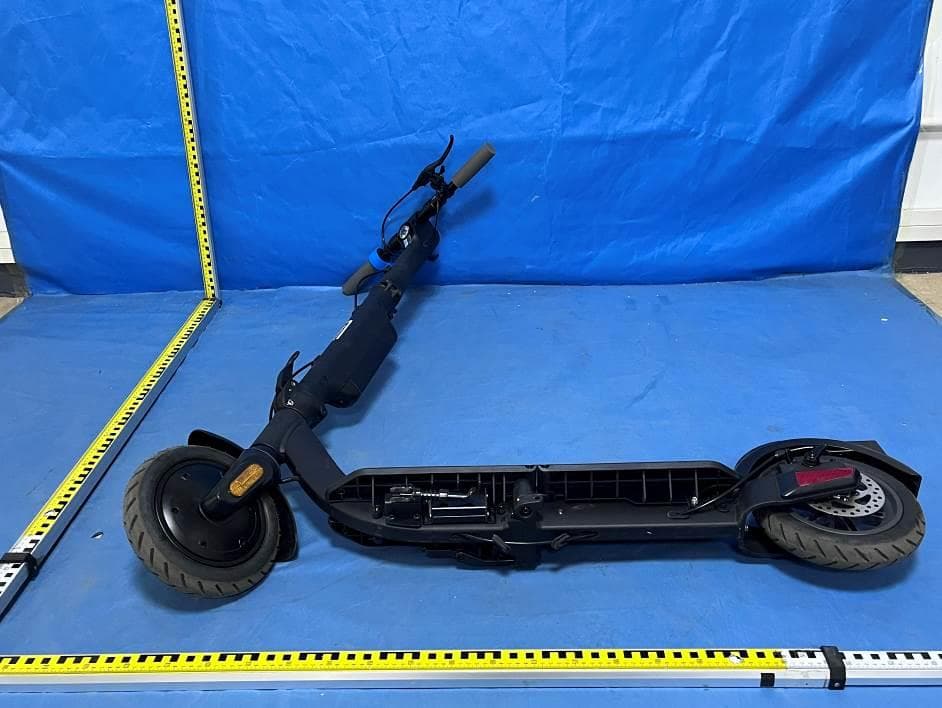
Click to zoom
Application Details
- Equipment Class
- DTS - Digital Transmission System
- Date of Grant
- Jan 16, 2023
- Application Purpose
- Original Equipment
- Date of Application
- Jan 16, 2023
- Equipment Note
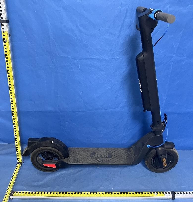
- ELECTRIC SCOOTER
- Frequency Range
- 2402.00000000 - 2480.00000000
- Company
- Riley Scooters Ltd.
- Country
- United Kingdom
Documents & Files
Document Text
Text extracted from the exhibit documents filed with the FCC. Open a document above to read the original.
Users Manual
RS3 User Manual 1 2 RS3 Scan me to unfold 3 4 Declaration of conformity Type of device: This declaration of conformity is issued under the sole responsibility of the manufacturer. Object of the declaraton: Electric scooter RS3 RILEY SCOOTER RS3 Model NO: Description: The object of the declaration described above is in conformity with the relevant Union harmonisation legislation: 2011/65/EU amended by 2015/863(EU) 2014/30/EU 2014/35/EU 2006/42/EC 2014/53/EU RoHS directive EMC Directive Low Voltage Directive Machinery Directive RED DIRECTIVE Riley Scooters Limited: Kings Lodge, London Road, Sevenoaks, TN15 6AR, United Kingdom References to the relevant harmonize standards used or references to other technical specification in relation to which conformity is declared: Name of manufacturer: Importer/Distributor contact detail: AUTHORISED SIGNATURE: Hayden Riley Founder & CEO Date: 2022-10-28 www.rileyscooters.com RILEY SCOOTERS LIMITED Address:Kings Lodge, London Road, Sevenoaks, TN16 5AR, United Kingdom BS EN 17128:2020 EN 17128:2020 EN 60335-1:2012 EN 60335-2-29:2004 EN IEC 55014-1:2021 EN IEC 55014-2:2021 EN 61558-1:2005 EN 61558-2-16:2009 EN 55014-1:2021 EN 55014-2:2015 EN 61000-3-2:2019+A1:2021 EN 61000-3-3:2013+A1:2019 5 6 15-16 17-19 17 18 19 Charging instructions 20 21 22 9. 24 23 8. Riley Scooter APP 10-14 10 11 12 13 14 Folding instructions Unfolding instructions 7-8 7 7-9 The manufacturer recommends riders be 14+ years old. WARNING! 7 8 Max Loading: 120 kg. 9 10 Base plate latchBase plate clip Brake lever Handlebar release clasp Accelerator / Throttle Battery clip Detachable battery Charging port Anti-slip mat Fender clip Fender Tail light Number plate LED display Folding latch Stem folding Clip Stem Folding spanner Motor Kickstand Discbrake Handle Headlight 11 12 brake lever to brake. Lightly 2.3 Unfolding instructions 1. Pull-out folding latch to release stem from base plate. clip 2. Pull stem up till it’s vertical. 3. Pull stem into place and secure the folding spanner. 5. Pull both handle bars upwards until they click into place. 4. Pull latch to release the upper stem. Fold stem upwards till vertical with the lower stem. 6. Un-hook base plate clip. Pull and hold the base plate latch. 7. While holding latch, push the folded deck outwards till aligned with upper deck. latch 8. Once in place, secure the base plate clip. Ensure it’s fastened tightly. 9. Push the deck down to secure it in place against the rear fender. View our instructional video here Brake lever 13 14 1. Push down on rear fender, pull up the deck, and fold towards the stem. 2. Press in button on base plate clip, and pull towards rear fender to release. 1. Push Battery clip in and hold. 2. Push the battery up, away from the bottom of the stem. 1. Insert the battery horizontally into the pole, while pushing the battery clip in. 2. When in, let go of the battery clip, and push battery down until firmly secure. 3. Pull and hold base plate latch and push the rear of the scooter towards the front wheel. 4. Fold the scooter firmly till it’s secure. Resecure the base plate clip to original position. 8. Slide folding latch back, and align to the hook on the base plate. Release clip when aligned to secure stem. 5. Pull handle bar release claps as arrows indicate, and completely fold handle bars toward stem. 6. Slide button upwards and unclip stem clasp, fold stem towards lower stem. 7. Slide button upwards and unclip folding spanner. Fold stem down to base plate. 2.4 Folding instructions button button button clip latch View our folding video here 15 16 lever to slow down or stop. 17 18 The instructions show you how to charge and maintain the battery and provide some safety notices and the technical specifications. Please use the battery properly according to these instructions to prolong battery life and performance. 4.1 Battery parameters NameParameter Type5.8AH Battery Charging timeApprox. 2 hours Voltage36V Working temperature0°C - 35°C Charging Temperature0°C - 35°C Max Charging Voltage42V Storage Time (at -10°C – 40°C) 3 months (full charge) Initial Volume5.8AH Max Charging Current2A 19 20 Product Unfolded size 1181x540x1133mm Folded size 649x272x474mm Height from baseplate to ground115mm Net weight16kg Tyre size8.5 inch pneumatic air tyre with inner tube Tyre pressure35 P.S.I (2.41 Bar) Waterproof levelIPx4 Basic Information Battery Capacity36V/5.8 AH Motor power350W Mileage per charge 15.5 miles (25km) Max speed 15.5 mph (25km/h) Max loading120kg Climbing angle15° Driving modes3 (beginner, eco, sport) Input voltage100-240Vac Frequency50-60Hz Output voltage42V Output current1.5A Store temperature-10°C-35°C 4.3 Charging instructions 1131mm 485mm Charging port Battery interface Charging method 1: Charging time is aprrox. 2 hours to fully charge. Charging method 2: 21 22 Potential problemSolution Unable to start upCheck to see if the battery is charged. Does not charge1. Check whether the plugboard has electricity. 2. Check the charger to see whether the AC plug is connected (whether the light is on). 3. Check the plug of the charger and the charging port of the e-scooter have been inserted correctly. WARNING! WARNING! 2324 1x Copy of Manufacturer's Limited Warranty 9. Riley Scooter APP Stay on the move with our app which connects directly to your scooter through Bluetooth. Get directions, view key riding info, and track your rides effortlessly. Features: • Cockpit showing key riding info • Lock and trace your scooter • Track your rides • Shop our range of accessories Note: When connecting to your scooter ensure your Bluetooth is enabled on your mobile device and the scooter is turned on. Scan to download the App. Alternativelly, go to the Google Play Store (Android) or the Apple App Store (iOS) and search Riley Scooters to download and install the App. Be advised there is a minimum Android/iOS/Bluetooth version required. See user materials for additional details. FCC Statement This equipment has been tested and found …
Text truncated - open the document above for the full version.
Cover Letter(s)
Riley Scooters Ltd. Agent Authorization Company: Riley Scooters Ltd. Address: Kings Lodge, London Road, Sevenoaks, TN15 6AR, United Kingdom Product Name: ELECTRIC SCOOTER Model Number(s): RS3, RS3-D, RS3-E Product Description: ELECTRIC SCOOTER We authorize MiCOM Labs Inc., 575 Boulder Court, Pleasanton, California 94566, USA, to act on our behalf on all matters concerning the certification of above named equipment. We declare that MiCOM Labs Inc. is allowed to forward all information related to the approval and certification of equipment to the regulatory agencies as required and to discuss any issues concerning the approval application. Any and all acts carried out by MiCOM Labs on our behalf shall have the same effect as acts of our own. Signature: Date: Jan.10,2023 Name: HAYDEN RILEY Title: general manager Company: Riley Scooters Ltd.
Cover Letter(s)
Riley Scooters Ltd. Family models declaration letter. Date: January 10, 2023 We Riley Scooters Ltd. Of Kings Lodge, London Road, Sevenoaks, TN15 6AR, United Kingdom Product: ELECTRIC SCOOTER Model Name: RS3 Serial Model: RS3-D, RS3-E Difference description of series models: All the model are the same circuit and RF module, except the model names. Thanks Sincerely Signature Name: HAYDEN RILEY Date: Jan.10,2023 Title: general manager
Cover Letter(s)
Riley Scooters Ltd. Office of Engineering Technology Federal Communications Commission 7435 Oakland Mills Road Columbia, MD 21046 USA Date: January 10, 2023 Subject; Request for Confidentiality FCC ID: 2A9WD-RS3 To Whom It May Concern, Pursuant to the provisions of the Commission’s rules Title 47 Sections §0.457 and §0.459, we are requesting the Commission to withhold the following attachment(s) as confidential documents from public disclosure indefinitely. These documents contain detailed system and equipment descriptions and are considered as proprietary information in operation of the equipment. The public disclosure of these documents might be harmful to our company and would give competitors an unfair advantage in the market. Schematic Diagram Block Diagram Parts List Operational Description Software Security Requirements for UNII devices In additional to above mentioned documents, in order to comply with the marketing regulations in Title 47 CFR §2.803 and the importation rules in Title 47 CFR §2.1204, while ensuring that business sensitive information remains confidential until the actual marketing of newly authorized devices, we request Short Term Confidentiality of the following attachment(s); External Photos Test Setup Photos Internal Photos User Manual For 45 days, pursuant to Public Notice DA 04-1705. OR For 180 days pursuant to KDB 726920 D01. It is our understanding that all measurement test reports, FCC ID label format and correspondence during the certification review process cannot be granted as confidential documents and this information will be available for public review once the grant of equipment authorization is issued. Sincerely, Signature: Name: HAYDEN RILEY Title: general manager
External Photos
- Page 1 of 4 - ET-22120963 Product Name: ELECTRIC SCOOTER Test Model No.: RS3 Ext Photos - Page 2 of 4 - ET-22120963 - Page 3 of 4 - ET-22120963 - Page 4 of 4 - ET-22120963 -----END-----
ID Label/Location Info
1 / 1 Label size:60mm*40mm
Internal Photos
- Page 1 of 5 - ET-22120963 Product Name: ELECTRIC SCOOTER Test Model No.: RS3 Internal photos - Page 2 of 5 - ET-22120963 - Page 3 of 5 - ET-22120963 RF ANT - Page 4 of 5 - ET-22120963 - Page 5 of 5 - ET-22120963 ------END-----
RF Exposure Info
FCC ID: 2A9WD-RS3 RF Exposure Evaluation TEST STANDARDS Follow the maximum permissible exposure (MPE) limits specified in 447498 D04 Interim General Radio Frequency Exposure Guidelines v01. The gain of the antenna used in the product was extracted from the supplied antenna data sheet and the maximum total power input to the antenna was also measured. Calculate the distance from the product to the MPE limit by the formula. LIMIT For single RF sources (i.e., any single fixed RF source, mobile device, or portable device, as defined in paragraph (b)(2) of this section): A single RF source is exempt if: (A) The available maximum time-averaged power is no more than 1 mW, regardless of separation distance. This exemption may not be used in conjunction with other exemption criteria other than those in paragraph (b)(3)(ii)(A) of Part 1.1307. Medical implant devices may only use this exemption and that in paragraph (b)(3)(ii)(A); (B) Or the available maximum time-averaged power or effective radiated power (ERP), whichever is greater, is less than or equal to the threshold Pth (mW) described in the following formula. This method shall only be used at separation distances (cm) from 0.5 centimeters to 40 centimeters and at frequencies from 0.3 GHz to 6 GHz (inclusive). Pth is given by: (C) Or using below table and the minimum separation distance (R in meters) from the body of a nearby person for the frequency (f in MHz) at which the source operates, the ERP (watts) is no more than the calculated value prescribed for that frequency. For the exemption in Table 1 to apply, R must be at least λ/2π, where λ is the free-space operating wavelength in meters. If the ERP of a single RF source is not easily obtained, then the available maximum time-averaged power may be used in lieu of ERP if the physical dimensions of the radiating structure(s) do not exceed the electrical length of λ/4 or if the antenna gain is less than that of a half-wave dipole (1.64 linear value). FCC ID: 2A9WD-RS3 For multiple RF sources: Multiple RF sources are exempt if: (A) The available maximum time-averaged power of each source is no more than 1 mW and there is a separation distance of two centimeters between any portion of a radiating structure operating and the nearest portion of any other radiating structure in the same device, except if the sum of multiple sources is less than 1 mW during the time-averaging period, in which case they may be treated as a single source (separation is not required). This exemption may not be used in conjunction with other exemption criteria other than those is paragraph (b)(3)(i)(A) of Part 1.1307. Medical implant devices may only use this exemption and that in paragraph (b)(3)(i)(A). (B) in the case of fixed RF sources operating in the same time-averaging period, or of multiple mobile or portable RF sources within a device operating in the same time averaging period, if the sum of the fractional contributions to the applicable thresholds is less than or equal to 1 as indicated in the following equation. Where: a = number of fixed, mobile, or portable RF sources claiming exemption using paragraph (b)(3)(i)(B) of Part 1.1307 for Pth, including existing exempt transmitters and those being added. b = number of fixed, mobile, or portable RF sources claiming exemption using paragraph (b)(3)(i)(C) of Part 1.1307 for Threshold ERP, including existing exempt transmitters and those being added. c = number of existing fixed, mobile, or portable RF sources with known evaluation for the specified minimum distance including existing evaluated transmitters. Pi = the available maximum time-averaged power or the ERP, whichever is greater, for fixed, mobile, or portable RF source i at a distance between 0.5 cm and 40 cm (inclusive). Pth,i = the exemption threshold power (Pth) according to paragraph (b)(3)(i)(B) of this section for fixed, mobile, or portable RF source i. FCC ID: 2A9WD-RS3 ERPj = the ERP of fixed, mobile, or portable RF source j. ERPth,j = exemption threshold ERP for fixed, mobile, or portable RF source j, at a distance of at least λ/2π according to the applicable formula of paragraph (b)(3)(i)(C) of Part 1.1307. Evaluatedk = the maximum reported SAR or MPE of fixed, mobile, or portable RF source k either in the device or at the transmitter site from an existing evaluation at the location of exposure. Exposure Limitk = either the general population/uncontrolled maximum permissible exposure (MPE) or specific absorption rate (SAR) limit for each fixed, mobile, or portable RF source k, as applicable from § 1.1310. Test Result of RF Exposure Evaluation Protocol Fre. (GHz) Output power (dBm) Tune-up power (dBm) Max tune-up power (dBm) ANT Gain ( dBi) Max EIRP (dBm) Max EIRP (mW) Separation distance (cm) Limit (mW) Result BLE 2.480 1.66 2±1 3 -0.58 2.42 1.75 5 2.76 PASS Note: 1. This device is portable device. 2. The source of the evaluation data results is based on the test report ET-22120963E 3. The Maxinum power is less than the limit, complies with the exemption requirements.
Test Report
Inverted F Antenna Specification Summary ITEMANT SPEC Model Name 2.4G ANT HorizontalVertical 2400MHz 2400MHz2500MHz2400MHz2400MHz 2500MHz Center Frequency -1.26-0.76-0.58-5.25-2.46-1.86 MAX. Gain -0.58dB PolarizationHorizontal and Vertical Azimuth Beam Pattern Omni-directional Impedance50 Ohm Antenna Length 38.20mm Manufacture ZHUHAI JIELI TECHNOLOGY CO.,LTD Antenna Photo & Length (mm) Horizontal: 2400 MHz 2450 MHz 2500 MHz Power (dBm) Max: 0 Min: -40 Scale: 5/div Gain (dB) Frequency (MHz) MaxMinAvg 2400-1.26174-30.0801-7.18716 2450-0.765802-36.5604-7.48023 2500-0.585582-22.0315-6.59127 Vertical: 2400 MHz 2450 MHz 2500 MHz Power (dBm) Max: 0 Min: -30 Scale: 5/div Gain(dB) Frequency (MHz) Max Min Avg 2400 -5.2537 -22.1424 -12.4294 2450 -2.4652 -24.5837 -10.4702 2500 -1.86120 -29.5214 -9.20432 ANT Test Labs:Attestation of Global Compliance Co., Ltd.
Test Report
Report No.: ET-22120963E This test report is valid for the tested samples only. It cannot be reproduced except in full without prior written consent of Shenzhen ETR Standard Technology Co., Ltd. TEST REPORT Applicant: Riley Scooters Ltd. Address of Applicant: Kings Lodge, London Road, Sevenoaks, TN15 6AR, United Kingdom Manufacturer/Factory: SHENZHEN TECHISON INTELLIGENT TECHNOLOGY CO, LTD. Address of Manufacturer Room107, Yinxing Technology Building, No.1301 Guanguang Road, Xinlan Community,Guanlan Street, Longhua District, Shenzhen Product Name: ELECTRIC SCOOTER Model No.: RS3, RS3-D, RS3-E Trade Mark: N/A FCC ID: 2A9WD-RS3 Applicable standards: FCC CFR Title 47 Part 15 Subpart C Section 15.247 Date of Test: Dec.22,2022- Dec.30,2022 Date of report issued: Jan.09,2023 Test Result : PASS * Remark: * In the configuration tested, the EUT complied with the standards specified above. The results shown in this test report refer only to the sample(s) tested, this test report cannot be reproduced, except in full without prior written permission of the company. The report would be invalid without specific stamp of test institute and the signatures of compiler and approver Prepared By Shenzhen ETR Standard Technology Co., Ltd. Address: No.103, No.10, Phase I, Zone 3, Xinxing Industrial Park, Xinhe, Fuhai Street, Bao'an District, Shenzhen, Guangdong, China Compiled by: Reviewed by: Approved by: Project Engineer Project Manager Authorized Signature - Page 2 of 31 - Report No.: ET-22120963E Tel:(86-755) 85259392 Email:[email protected] Web: www.etrlab.cn No.103, No.10, Phase I, Zone 3, Xinxing Industrial Park, Xinhe, Fuhai Street, Bao'an District, Shenzhen, Guangdong, China Report Revision History Report No. Description Issue Date ET-22120963E Original Jan.09,2023 - Page 3 of 31 - Report No.: ET-22120963E Tel:(86-755) 85259392 Email:[email protected] Web: www.etrlab.cn No.103, No.10, Phase I, Zone 3, Xinxing Industrial Park, Xinhe, Fuhai Street, Bao'an District, Shenzhen, Guangdong, China Contents Page 1. TEST SUMMARY ......................................................................................................................................4 2. GENERAL INFORMATION .......................................................................................................................5 2.1 GENERAL DESCRIPTION OF EUT .................................................................................................................5 2.2 TEST MODE ................................................................................................................................................7 2.3 DESCRIPTION OF SUPPORT UNITS ...............................................................................................................7 2.4 DEVIATION FROM STANDARDS .....................................................................................................................7 2.5 ABNORMALITIES FROM STANDARD CONDITIONS ...........................................................................................7 2.6 TEST FACILITY ............................................................................................................................................7 2.7 TEST LOCATION ..........................................................................................................................................7 2.8 ADDITIONAL INSTRUCTIONS .........................................................................................................................7 3. TEST INSTRUMENTS LIST ......................................................................................................................8 4. TEST RESULTS AND MEASUREMENT DATA .......................................................................................9 4.1 ANTENNA REQUIREMENT .............................................................................................................................9 4.2 CONDUCTED EMISSIONS ...........................................................................................................................10 4.3 CONDUCTED PEAK OUTPUT POWER ..........................................................................................................13 4.4CHANNEL BANDWIDTH ...............................................................................................................................14 4.5 POWER SPECTRAL DENSITY ......................................................................................................................16 4.6 BAND EDGES ............................................................................................................................................18 Conducted Emission Method ...................................................................................................................18 Radiated Emission Method ......................................................................................................................19 4.7 SPURIOUS EMISSION .................................................................................................................................21 Conducted Emission Method ...................................................................................................................21 Radiated Emission Method ......................................................................................................................23 5. TEST SETUP PHOTO .............................................................................................................................31 6. EUT CONSTRUCTIONAL DETAILS .......................................................................................................31 - Page 4 of 31 - Report No.: ET-22120963E Tel:(86-755) 85259392 Email:[email protected] Web: www.etrlab.cn No.103, No.10, Phase I, Zone 3, Xinxing Industrial Park, Xinhe, Fuhai Street, Bao'an District, Shenzhen, Guangdong, China 1. Test Summary Test Item Section Result Test by Ante…
Text truncated - open the document above for the full version.
Test Setup Photos
ET-22120963 Page 1 of 2 Product Name: ELECTRIC SCOOTER Test Model No.: RS3 Test Setup Photo Radiated emissions 30MHz to1GHz Above 1GHz ET-22120963 Page 2 of 2 Conducted Emission ------End------
Contact Information
Applicant
HAYDEN RILEY
Technical Contact
Test Firm
Shenzhen ETR Standard Technology Co., Ltd.Smith Chen
[email protected]+86 755-85259392
Technical Specifications
| # | Rule Parts | Frequency Range | Power Output |
|---|---|---|---|
| 1 | 15C | 2.40 GHz - 2.48 GHz | 1.50 mW |
Other Applications from Riley Scooters Ltd.
2A9WD-RS2
Jan 15, 2023ELECTRIC SCOOTER
Equipment Class
DTS - Digital Transmission System