2A9WT-CS2PopTimer Pro100 Glove Sensor
Caught Stealing LLC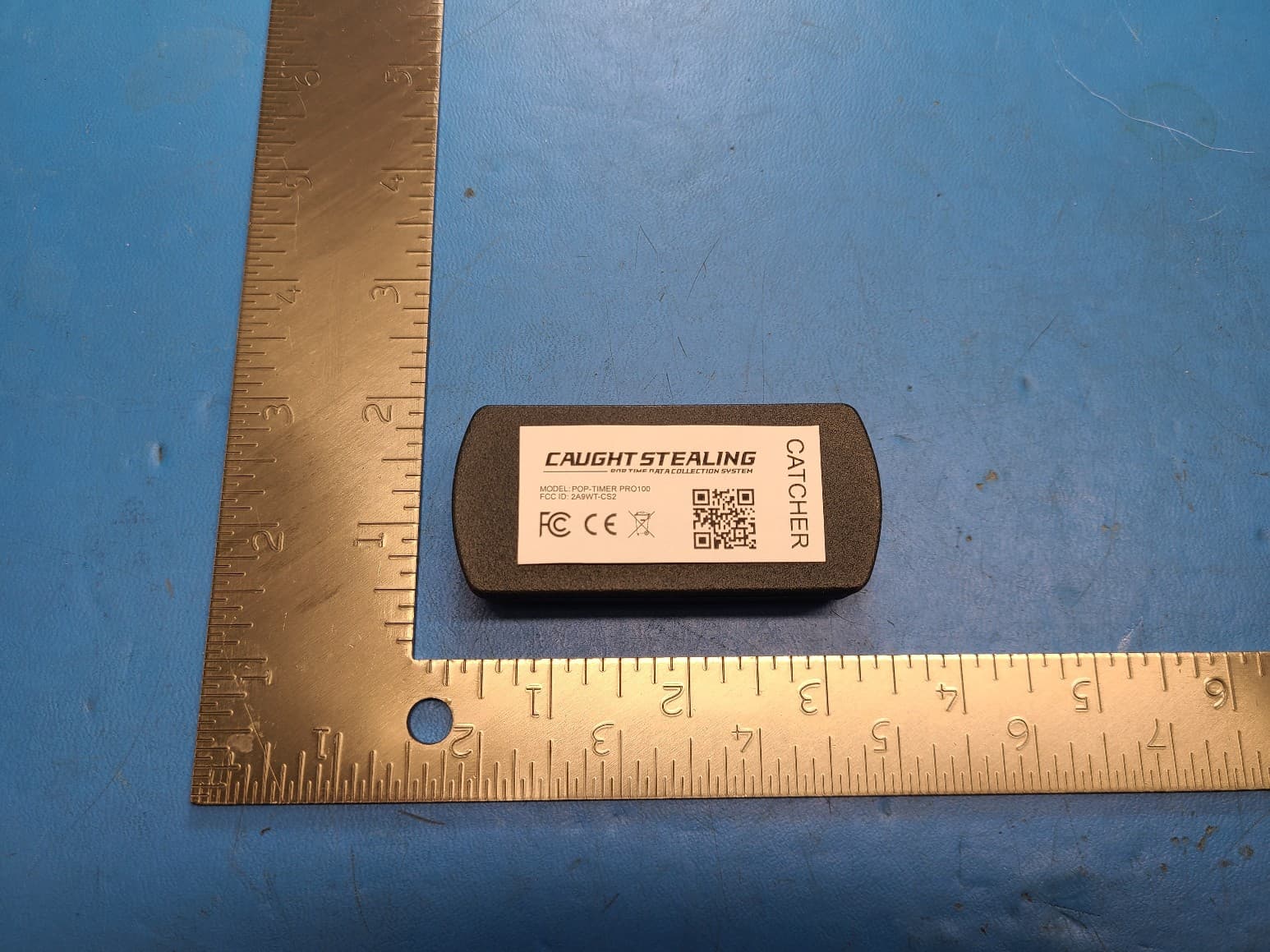
Click to zoom
Application Details
- Equipment Class
- UWB - Ultra Wideband Transmitter
- Date of Grant
- Jul 09, 2023
- Application Purpose
- Original Equipment
- Date of Application
- Jun 29, 2023
- Equipment Note
- PopTimer Pro100 Glove Sensor
- Frequency Range
- 6240.00000000 - 6739.20000000
- Company
- Caught Stealing LLC
- Country
- United States
Documents & Files
Document Text
Text extracted from the exhibit documents filed with the FCC. Open a document above to read the original.
Cover Letter(s)
February 27, 2023 Federal Communications Commission Authorization & Evaluation Division 7345 Oakland Mills Road Columbia, Maryland 21046 RE: Long-Term Confidentiality Request for (Pop-Timer PRO100 FCC ID: 2A9WT-CSW ) To Whom It May Concern: This letter serves as an official request for confidentiality under § 0.457(d) and § 0.459 of CFR 47. We have requested that the following documents required to be submitted with this application be permanently withheld from public review. Block Diagram Schematics Theory of Operation Tune Up Procedure Parts List/BOM These documents contain detailed system and equipment descriptions and related information about the product, which manufacturer/applicant considers to be proprietary, confidential, and a custom design and otherwise, would not release to the general public. Since this design is a basis from which future technological products will evolve, manufacturer/applicant feels that this information would be of benefit to its competitors, and that the disclosure of the information in these documents would give our competitors an unfair advantage in the market. Please contact me if there is any information you may need. Sincerely, Matt Ceriani President Caught Stealing LLC 1014 N. Indian Paintbrush Cr. Payson, AZ. 85541
Cover Letter(s)
April 27, 2023 Federal Communications Commission Authorization & Evaluation Division 7345 Oakland Mills Road Columbia, Maryland 21046 RE: LETTER OF AGENT AUTHORIZATION To Whom It May Concern: We, Caught Stealing LLC, hereby authorize Compliance Testing, LLC to act on our behalf in all matters relating to application for equipment authorization, including the signing of all documents relating to these matters. We also hereby certify that no party to the application authorized hereunder is subject to the denial of benefits, including FCC benefits, pursuant to Section 5301 of the Anti-Drug Abuse Act of 1988, 21 U.S.C.853(a). Sincerely, Matt Ceriani President Caught Stealing LLC 1014 N. Indian Paintbrush Cr. Payson, AZ. 85541
External Photos
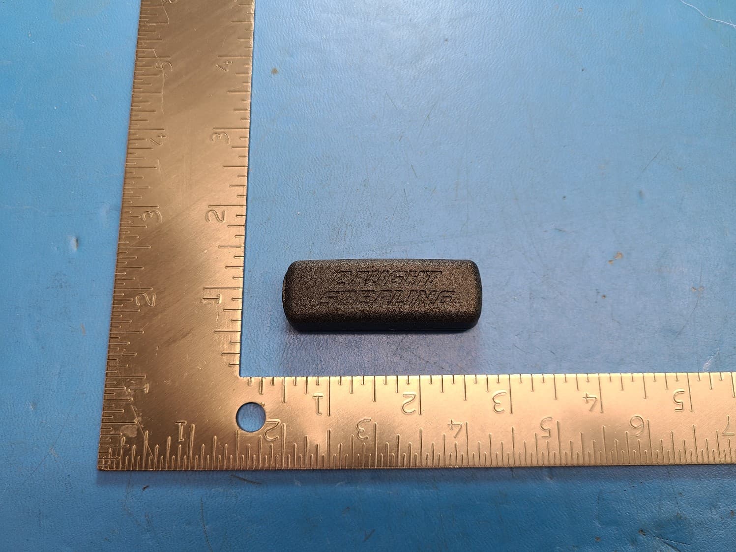
PopTimer Pro100 Glove Sensor External Photos
ID Label/Location Info
Device Label Artwork
Internal Photos
PCB Back (for reference only) PCB Front S-Band Antenna #1 S-Band Antenna #2 C-Band Antenna TDK HHM1595A1 3-8Ghz RF Balun Mini-Circuits QCS-312+ 1.7 –3.1Ghz 90° Hybrid Splitter UWB SOC BLE SOC Matching Network Poptimer Pro100 Glove Sensor Internal Photos
Parts List/Tune Up Info
SPE-17-8-057-E Accura UWCCP.01 Part No: UWCCP.01 Description: 6~7 GHz Ultra-Wideband (UWB), Embedded Circular Polarized, SMT Chip Antenna Features: SMD UWB Chip Antenna For European and USA UWB Applications In Channels 5 Uses • Centimeter Level Positioning • Indoor Positioning • Follow Me Autonomous Positioning • Time of Arrival (TOA) Applications • Angle of Arrival (AOA) Applications • Remote Keyless Entry (RKE)Security Frequency: 6.0 – 7.0 GHz Dims: 14.3mm*8.35mm*2mm RoHS and REACH compliant SPE-17-8-057-F www.taoglas.com Taoglas makes no warranties based on the accuracy or completeness of the contents of this document and reserves the right to make changes to specifications and product descriptions at any time without notice. Taoglas reserves all rights to this document and the information contained herein. Reproduction, use or disclosure to third parties without express permission is strictly prohibited. 1. Introduction 3 2. Specifications 5 3. Antenna Characteristics 6 4. Radiation Patterns 11 5. Mechanical Drawing 13 6. Antenna Integration Guide 14 7. Packaging 22 8. Solder Reflow Profile 23 9. Application Note 24 Changelog 31 SPE-17-8-057-F www.taoglas.com The UWCCP.01 chip antenna, at 14.3*8.35*2 mm, is a small form factor embedded Ultra-Wideband (UWB) antenna with high efficiencies across the pulsed UWB communications operational channel 5 (6.25 GHz – 6.75 GHz). It is circularly polarized and hence very suitable for use in mobile tags in standard Time of Arrival (ToA) and advanced Angle of Arrival (AoA) localization systems. It is mounted to a PCB via standard SMT reflow process. The UWCCP.01 antenna is a durable ceramic antenna that has a peak gain of 6.5dBi, an efficiency of more than 70% across the channel 5 and is designed to be mounted directly onto a PCB. It is an ideal choice for any device maker that needs to keep manufacturing costs down over the lifetime of a product. Like all such antennas, care should be taken to mount the antenna at least 3mm from metal components or surfaces, and ideally 5mm for best radiation efficiency. Ultra-Wideband (also known as UWB) is a low power digital wireless technology for transmitting large amounts of digital data over a wide spectrum of frequency bands typically spanning more than 500MHz with very low power for short distances. The low power requirements of UWB mean increased battery life of sensors and tags leading to reduction in overall operational costs. Besides the chip antenna line, Taoglas has also developed innovative and new-to-market flexible embedded UWB antennas designed for seamless integration on plastics and using highly flexible micro-coaxial cable mounting while achieving high performance where space is limited. Taoglas UWB antennas have been designed for use with the recently launched Decawave ScenSor DW1000 module and are also compatible with any other UWB sensor modules on the market. 1. Introduction 1. Introduction 1. Introduction 1. Introduction 1. Introduction 1. Introduction 1. Introduction 1. Introduction SPE-17-8-057-F www.taoglas.com 1.1 Applications of Pulsed UWB antenna Technology • Radar - These short-pulsed antennas provide very fine range resolution and precision distance and positioning measurement capabilities. UWB signals enable inexpensive high definition radar antennas which find use in automotive sensors, smart airbags and precision surveying applications amongst many others. • Home Network Connectivity - Smart home and entertainment systems can take advantage of high data rates for streaming high quality audio and video contents in real time for consumer electronics and computing within a home environment. • Position location & Tracking - UWB antennas also find use in Position Location and Tracking applications such as locating patients in case of critical condition, hikers injured in remote areas, tracking cars, and managing a variety of goods in a big shopping malls. UWB offers better noise immunity and better accuracy to within a few cm compared to current localization technologies such as Assisted GPS for Indoors, Wi-Fi and cellular which are at best able to offer meter level precision. Tethered Indoor Positioning UWB systems that measure the angles of arrival of ultra-wideband (UWB) radio signals perform triangulation by using multiple sensors to communicate with a tag device. SPE-17-8-057-F www.taoglas.com Electrical STANDARD EU UWB USA UWB Channel 5 Operation Frequency (GHz) 6.24-6.74 Return Loss (dB) <-8 Efficiency (%) 80 Peak Gain (dBi) 6.5 Max Axial Ratio (dB) 6 Radiation Properties Omnidirectional Polarization Circular Impedance (Ohms) 50 Max input Power (Watts) 10 Mechanical Dimension 14.8mm x 8.4mm x 2mm Material Ceramic Environmental Operation Temperature -40°C to 85°C Storage Temperature -40°C to 85°C Moisture Sensitivity Level (MSL) 3 (168 Hours) Humidity 40% to 90% 2. Specifications 3. Antenna Characteristics2. Specifications 3. Antenna Characteristics 4. Antenna Radiation Patterns3. Antenna Characteristics2. Specifications 3. Antenna Characteristics2. Specifications 3. Antenna Characteristics 4. Antenna Radiation Patterns3. Antenna Characteristics 4. Antenna Radiation Patterns 4. Antenna Radiation Patterns3. Antenna Characteristics 4. Antenna Radiation Patterns3. Antenna Characteristics2. Specifications Results obtained for antenna on Standard Evaluation Board size 16 mm x 12 mm, with 16 mm x 4.2 mm ground plane. SPE-17-8-057-F www.taoglas.com 3.1 Return Loss 3.2 VSWR 3. Antenna Characteristics 4. Antenna Radiation Patterns3. Antenna Characteristics 4. Antenna Radiation Patterns 4. Antenna Radiation Patterns3. Antenna Characteristics 4. Antenna Radiation Patterns3. Antenna Characteristics 4. Antenna Radiation Patterns 4. Antenna Radiation Patterns 4. Antenna Radiation Patterns 4. Antenna Radiation Patterns3. Antenna Characteristics 4. Antenna Radiation Patterns3. Antenna Characteristics SPE-17-8-057-F www.taoglas.com 3.3 Efficiency [%] 3.4 Peak Gain SPE-17-8-057-F www.taoglas.c…
Text truncated - open the document above for the full version.
RF Exposure Info
Toll -free: (866) 311-3268 Fax: (480) 926-3598 www.ComplianceTesting.com [email protected] p22c0009_FCC_Part 1.1310_Rev 1.0 Page 1 of 7 Test Report Prepared for: Southwest Engineering Concepts Model: i POP Glove Sensor Description: Glove Sensor Serial Number: NA FCC ID: 2A9WT-CS2 IC ID: 30031-CS2 To FCC Part 1 .1310 Date of Issue: March 9, 2021 On the behalf of the applicant: Southwest Engineering Concepts 3235 North Arizona Avenue, Suite 2 Chandler, AZ 85225 Attention of: Greg Mills, Principal Engineer Ph: (480) 500-1824 E-Mail: [email protected] Prepared By Compliance Testing, LLC 1724 S. Nevada Way Mesa, AZ 85204 (480) 926-3100 phone / (480) 926-3598 fax www.compliancetesting.com Project No: p22c0009 John Michalowicz Project Test Engineer This report may not be reproduced, except in full, without written permission from Compliance Testing All results contained herein relate only to the sample tested p22c0009_FCC_Part 1.1310_Rev 1.0 Page 2 of 7 Test Report Revision History Revision Date Revised By Reason for Revision 1.0 6/12/2023 John Michalowicz Original Document p22c0009_FCC_Part 1.1310_Rev 1.0 Page 3 of 7 ANAB Compliance Testing, LLC, has been accredited in accordance with the recognized International Standard ISO/IEC 17025:2017. This accreditation demonstrates technical competence for a defined scope and the operation of a laboratory quality management system (refer to the joint ISO-ILAC-IAF Communiqué dated January 2009). The tests results contained within this test report all fall within our scope of accreditation, unless noted below. Please refer to http://www.compliancetesting.com/labscope.html for current scope of accreditation. FCC Site Reg. #349717 IC Site Reg. #2044A-2 Non-accredited tests contained in this report: N/A EUT Description Model: Glove Sensor Description: Sensor placed on Glove Firmware: v1 Software: N/A Serial Number: N/A Additional Information: The EUT is a companion device to the Wrist Sensor. The EUT incorporates a UWB transmitter centered at 6.491 GHz. . The EUT is an original filing. The EUT incorporates a chip antenna with a peak gain of 6.5 dBi. The antenna gain was provided by the manufacturer. p22c0009_FCC_Part 1.1310_Rev 1.0 Page 4 of 7 MPE Evaluation This is a portable device used in Uncontrolled Exposure environment. Limits Controlled Exposure 47 CFR 1.1310 Table 1, (A) 0.3-3.0 MHz: Limit [mW/cm²] = 100 3.0-30 MHz: Limit [mW/cm²] = (900/f²) 30-300 MHz: Limit [mW/cm²] = 1.0 300-1500 MHz: Limit [mW/cm²] = f/300 1500-100,000 MHz Limit [mW/cm²] = 5 Limits Uncontrolled Exposure 47 CFR 1.1310 Table 1, (B) 0.3-1.234 MHz: Limit [mW/cm²] = 100 1.34-30 MHz: Limit [mW/cm²] = (180/f²) 30-300 MHz: Limit [mW/cm²] = 0.2 300-1500 MHz: Limit [mW/cm²] = f/1500 1500-100,000 MHz Limit [mW/cm²] = 1.0 Test Data Test Frequency, MHz 6489.5 Power, Conducted, mW (P) peak 0.478 Power, Conducted, mW (P) avg 0.0000474 Antenna Gain Isotropic 6.5 dBi Antenna Gain Numeric (G) 4.47 Antenna Type chip Distance (R) 0.5 cm Test Frequency, MHz 2480 Power, Conducted, mW (P) 1.294 Antenna Gain Isotropic 3.12 dBi Antenna Gain Numeric (G) 2.05 Antenna Type chip Distance (R) 0.5 cm Transmitter 1Formula S = P*G / 4*PI*r 2 6489 MHzPower Density (S) mw/cm 2 Power mW (P)Neumaric Gain (G)Distance (r 2 ) cm 0.00006747710.00004744.470.5 Transmitter 2Formula S = P*G / 4*PI*r 2 2480 MHzPower Density (S) mw/cm 2 Power mW (P)Neumaric Gain (G)Distance (r 2 ) cm 0.84480891721.2942.050.5 Co-located power density0.8448763943 p22c0009_FCC_Part 1.1310_Rev 1.0 Page 5 of 7 Per KDB This is for calculating a SAR exclusion per KDB 447498. 1) The 1-g and 10-g SAR test exclusion thresholds for 100 MHz to 6 GHz at test separation distances ≤ 50 mm are determined by: [(max. power of channel, including tune-up tolerance, mW)/(min. test separation distance, mm)] · [√f(GHz)] ≤ 3.0 for 1-g SAR and ≤ 7.5 for 10-g extremity SAR,25 where • f(GHz) is the RF channel transmit frequency in GHz • Power and distance are rounded to the nearest mW and mm before calculation26 • The result is rounded to one decimal place for comparison • 3.0 and 7.5 are referred to as the numeric thresholds in the step 2 below The test exclusions are applicable only when the minimum test separation distance is ≤ 50 mm and for transmission frequencies between 100 MHz and 6 GHz. When the minimum test separation distance is < 5 mm, a distance of 5 mm according to 5) in section 4.1 is applied to determine SAR test exclusion. END OF TEST REPORT
Test Report
p22c0009_FCC_Part 15.519_Rev 2.0 Page 1 of 17 Test Report Prepared for: Southwest Engineering Concepts Model: i POP Glove Sensor Description: Glove Sensor Serial Number: NA FCC ID: 2A9WT-CS2 IC ID: 30031-CS2 To FCC Part 15.519 IC RSS-2 20 Issue 1 Date of Issue: February 20, 2023 On the behalf of the applicant: Southwest Engineering Concepts 3235 North Arizona Avenue, Suite 2 Chandler, AZ 85225 Attention of: Greg Mills, Principal Engineer Ph: (480) 500-1824 E-Mail: [email protected] Prepared By Compliance Testing, LLC 1724 S. Nevada Way Mesa, AZ 85204 (480) 926-3100 phone / (480) 926-3598 fax www.compliancetesting.com Project No: p22c0009 Test Result - Pass John Michalowicz Project Test Engineer This report may not be reproduced, except in full, without written permission from Compliance Testing. All results contained herein relate only to the sample tested. p22c0009_FCC_Part 15.519_Rev 2.0 Page 2 of 17 Test Results Summary FCC 15.519 Specification RSS-220 Specification Test Name Pass, Fail, N/A Comments 15.519(b) Section 4.1 10dBc Bandwidth Pass 15.519(a) Section 5.3 Cessation Time Pass 15.519(e), Section 4.1 Maximum Peak Power Pass 15.519(c) Section 4.1 Maximum Average Emission Pass 15.519(c) Sections 3.4 Radiated Emissions Pass 15.519(d) Section 4.1 Emissions in the 1164 – 1240 MHz and 1559 – 1610 MHz Pass 15.207 RSS-GEN Section 8.8 A/C Powerline Conducted Emissions N/A EUT cannot transmit while charging Statements of conformity are reported as: • Pass - the measured value is below the acceptance limit, acceptance limit = test limit. • Fail - the measured value is above the acceptance limit, acceptance limit = test limit. References Description CFR47, Part 15, Subpart F Ultra-Wideband Operation ANSI C63.10-2013 American National standard for testing Unlicensed Wireless Devices ISO/IEC 17025:2005 General requirements for the Competence of Testing and Calibrations Laboratories KDB 393764 D01 v02r01 ULTRA-WIDEBAND (UWB) DEVICES FREQUENTLY ASKED QUESTIONS p22c0009_FCC_Part 15.519_Rev 2.0 Page 3 of 17 Test Report Revision History Revision Date Revised By Reason for Revision 1.0 2/20/2023 John Michalowicz Original Document 2.0 6/14/2023 John Michalowicz Updated additional information section to include frequency band. Updated 10 dBc BW section. Included GPS band measurement 15.519(d) p22c0009_FCC_Part 15.519_Rev 2.0 Page 4 of 17 Table of Contents Description Page Standard Test Conditions Engineering Practices ............................................................................... 7 10dBc bandwidth ................................................................................................................................. 9 Cessation Time ................................................................................................................................. 10 Peak Power and Maximum Average Emission ................................................................................. 11 Radiated Measurements above 960MHz .......................................................................................... 13 Test Equipment Utilized .................................................................................................................... 17 p22c0009_FCC_Part 15.519_Rev 2.0 Page 5 of 17 ANAB Compliance Testing, LLC, has been accredited in accordance with the recognized International Standard ISO/IEC 17025:2017. This accreditation demonstrates technical competence for a defined scope and the operation of a laboratory quality management system (refer to the joint ISO-ILAC-IAF Communiqué dated January 2009). The tests results contained within this test report all fall within our scope of accreditation, unless noted below. Please refer to http://www.compliancetesting.com/labscope.html for current scope of accreditation. FCC Site Reg. #349717 IC Site Reg. #2044A-2 Non-accredited tests contained in this report: N/A p22c0009_FCC_Part 15.519_Rev 2.0 Page 6 of 17 The applicant has been cautioned as to the following 15.21 - Information to User The user’s manual or instruction manual for an intentional radiator shall caution the user that changes or modifications not expressly approved by the party responsible for compliance could void the user’s authority to operate the equipment. 15.27(a) - Special Accessories Equipment marked to a consumer must be capable of complying with the necessary regulations in the configuration in which the equipment is marketed. Where special accessories, such as shielded cables and/or special connectors are required to enable an unintentional or intentional radiator to comply with the emission limits in this part, the equipment must be marketed with, i.e. shipped and sold with, those special accessories. However, in lieu of shipping or packaging the special accessories with the unintentional or intentional radiator, the responsible party may employ other methods of ensuring that the special accessories are provided to the consumer without an additional charge. Information detailing any alternative method used to supply the special accessories for a grant of equipment authorization or retained in the verification records, as appropriate. The party responsible for the equipment, as detailed in § 2.909 of this chapter, shall ensure that these special accessories are provided with the equipment. The instruction manual for such devices shall include appropriate instructions on the first page of text concerned with the installation of the device that these special accessories must be used with the device. It is the responsibility of the user to use the needed special accessories supplied with the equipment. p22c0009_FCC_Part 15.519_Rev 2.0 Page 7 of 17 Standard Test Conditions Engineering Practices Except as noted herein, the following conditions and procedures were observed during the testing: In accordance with ANSI C63.10-2013 and unless otherwise indicated in the specific measurement results, the ambient temperature of the actual EUT was maintained…
Text truncated - open the document above for the full version.
Test Setup Photos
Test Setup Photos FCC ID: 2A9WT-CS2 IC ID: 30031-CS2
Test Setup Photos
Test Setup Photos FCC ID: 2A9WT-CS2 IC ID: 30031-CS2
Test Setup Photos
Test Setup Photos FCC ID: 2A9WT-CS2 IC ID: 30031-CS2
Contact Information
Applicant
Greg Mills
Technical Contact
Southwest Engineering Concepts LLCGreg Mills
[email protected]4805001824
3235 N. Arizona Ave. · Chandler, Arizona · United States
Test Firm
Compliance Testing, LLCMichael Schafer
[email protected]480-926-3100
Technical Specifications
| # | Rule Parts | Frequency Range | Power Output |
|---|---|---|---|
| 1 | 15F | 6.24 GHz - 6.74 GHz | - |
Other Applications from Caught Stealing LLC
2A9WT-CSW
Jun 29, 2023PopTimer Pro100 Wrist Sensor
Equipment Class
DTS - Digital Transmission System