2A9WT-CSWPopTimer Pro100 Wrist Sensor
Caught Stealing LLC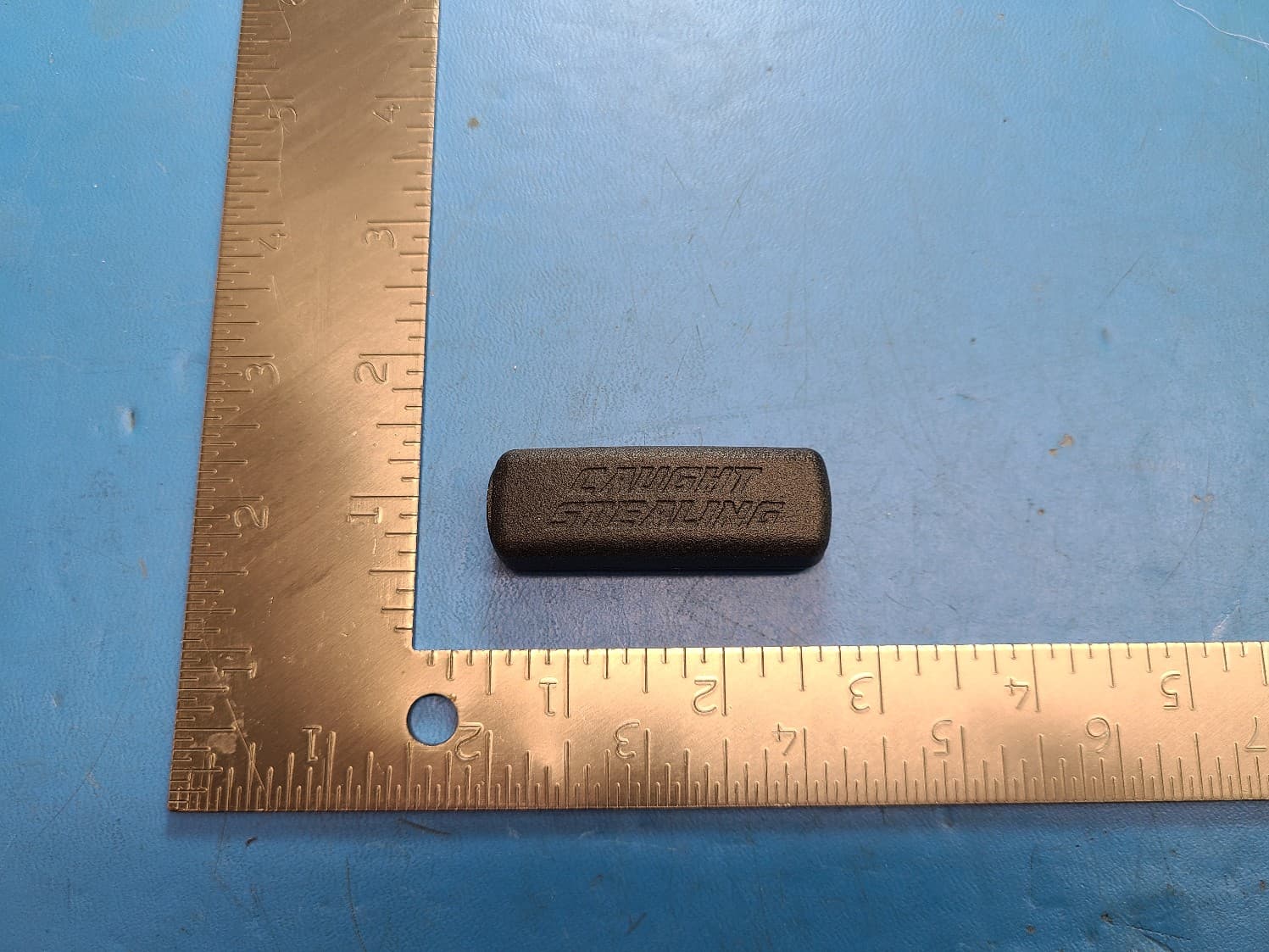
Click to zoom
Application Details
- Equipment Class
- DTS - Digital Transmission System
- Date of Grant
- Jun 29, 2023
- Application Purpose
- Original Equipment
- Date of Application
- Jun 28, 2023
- Equipment Note
- PopTimer Pro100 Wrist Sensor
- Frequency Range
- 2402.00000000 - 2480.00000000
- Company
- Caught Stealing LLC
- Country
- United States
Documents & Files
Document Text
Text extracted from the exhibit documents filed with the FCC. Open a document above to read the original.
Cover Letter(s)
February 27, 2023 Federal Communications Commission Authorization & Evaluation Division 7345 Oakland Mills Road Columbia, Maryland 21046 RE: Long-Term Confidentiality Request for (Pop-Timer PRO100 FCC ID: 2A9WT-CSW ) To Whom It May Concern: This letter serves as an official request for confidentiality under § 0.457(d) and § 0.459 of CFR 47. We have requested that the following documents required to be submitted with this application be permanently withheld from public review. Block Diagram Schematics Theory of Operation Tune Up Procedure Parts List/BOM These documents contain detailed system and equipment descriptions and related information about the product, which manufacturer/applicant considers to be proprietary, confidential, and a custom design and otherwise, would not release to the general public. Since this design is a basis from which future technological products will evolve, manufacturer/applicant feels that this information would be of benefit to its competitors, and that the disclosure of the information in these documents would give our competitors an unfair advantage in the market. Please contact me if there is any information you may need. Sincerely, Matt Ceriani President Caught Stealing LLC 1014 N. Indian Paintbrush Cr. Payson, AZ. 85541
Cover Letter(s)
April 27, 2023 Federal Communications Commission Authorization & Evaluation Division 7345 Oakland Mills Road Columbia, Maryland 21046 RE: LETTER OF AGENT AUTHORIZATION To Whom It May Concern: We, Caught Stealing LLC, hereby authorize Compliance Testing, LLC to act on our behalf in all matters relating to application for equipment authorization, including the signing of all documents relating to these matters. We also hereby certify that no party to the application authorized hereunder is subject to the denial of benefits, including FCC benefits, pursuant to Section 5301 of the Anti-Drug Abuse Act of 1988, 21 U.S.C.853(a). Sincerely, Matt Ceriani President Caught Stealing LLC 1014 N. Indian Paintbrush Cr. Payson, AZ. 85541
External Photos
PopTimer Pro100 Wrist Sensor External Photos
ID Label/Location Info
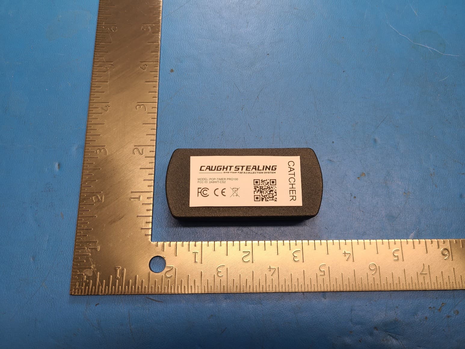
Device Label Artwork
Internal Photos
PCB Back (for reference only) PCB Front S-Band Antenna #1 S-Band Antenna #2 Mini-Circuits QCS-312+ 1.7 –3.1Ghz 90° Hybrid Splitter BLE SOC Matching Network Poptimer Pro100 Wrist Sensor Internal Photos
Parts List/Tune Up Info
Approval sheet Page 1 of 9 ASC_RFANT5220110A2T_V03 May. 2013 RFANT Series – RoHS Compliance MULTILAYER CERAMIC ANTENNA Halogens Free Product 2.4 GHz ISM Band Working Frequency P/N: RFANT5220110A2T *Contents in this sheet are subject to change without prior notice. Approval sheet Page 2 of 9 ASC_RFANT5220110A2T_V03 May. 2013 FEATURES 1. Surface Mounted Devices with a small dimension of 5.2 x 2.0 x 1.1 mm 3 meet future miniaturization trend. 2. Embedded and LTCC (Low Temperature Co-fired Ceramic) technology is able to future integrate with system design as well as beautifying the housing of final product. 3. High Stability in Temperature / Humidity Change APPLICATIONS 1. Bluetooth 2. Wireless LAN 3. HormRF 4. ISM band 2.4GHz wireless applications CONSTRUCTION Figure Symbol Dimension (mm) L 5.20 ± 0.20 W 2.00 ± 0.20 T 1.15 ± 0.10 A 0.40 ± 0.25 PIN Connection 1 Feeding 2 Identification Mark 3 Soldering terminal P1 P3 P2 Approval sheet Page 3 of 9 ASC_RFANT5220110A2T_V03 May. 2013 ELECTRICAL CHARACTERISTICS RFANT5220110A2T Specification Working Frequency Range 2.4 GHz ~ 2.5GHz Gain 2 dBi (Typical) VSWR 2 max. Polarization Linear Azimuth Beamwidth Omni-directional Impedance 50Ω Rated Power (max.) 3 Watts Maximum Input Power 5 Watts for 5 minutes Operation Temperature -40 ̊C ~ +85 ̊C Remark: The specification is defined based on the test board dimension as in below SOLDER LAND PATTERN DESIGN Figure To 50Ω RF I/O GROUND 6.4 1.0 1.0 4.4 2.0 Ground Soldering Pad 50 ΩTransmission Line Unit : mm 1.0 To 50Ω RF I/O GROUND 6.46.4 1.0 1.0 4.4 2.0 Ground Soldering Pad 50 ΩTransmission Line Unit : mm 1.0 Approval sheet Page 4 of 9 ASC_RFANT5220110A2T_V03 May. 2013 Antenna on Test Board ( FR4 Thickness 0.8mm) Antenna S11 on Test Board Empty Area 50Ω ΩΩ ΩFeed line GROUND 30x18 mm 2.0mm 2.5mm 18mm WTC B Empty Area 18x9 mm 1mm Empty Area 50Ω ΩΩ ΩFeed line GROUND 30x18 mm 2.0mm 2.5mm 18mm WTC B WTC B Empty Area 18x9 mm 1mm -14.96 dB @ 2.40 GHz -22.21 dB @ 2.45 GHz -10.26 dB @ 2.50 GHz Approval sheet Page 5 of 9 ASC_RFANT5220110A2T_V03 May. 2013 RADIATION PATTERN Radiation Pattern and Gain were dependent on measurement board design. The specification of RFANT5220110A2T antenna was measured based on the PCB size and installation position as shown in the below figure Test Board Vertical Horizontal Y - Z Plane Average Gain= 1.01 dBi -40 -30 -20 -10 0 0 30 60 90 120 150 180 210 240 270 300 330 Peak Gain = 3.12dBi Average Gain = 0.29dBi -40 -30 -20 -10 0 0 30 60 90 120 150 180 210 240 270 300 330 Peak Gain=-0.33dBi Average Gain=-7.21dBi X - Z Plane Average Gain= -1.737 dBi -40 -30 -20 -10 0 0 30 60 90 120 150 180 210 240 270 300 330 Peak Gain= -2.91 dBi Average Gain= -9.27dBi X Cut -40 -30 -20 -10 0 0 30 60 90 120 150 180 210 240 270 300 330 Peak Gain= 2.88 dBi Average Gain= -2.58 dBi X - Y Plane Average Gain= -2.799 dBi -40 -30 -20 -10 0 0 30 60 90 120 150 180 210 240 270 300 330 Peak Gain= -1.73 dBi Average Gain= -8.07 dBi -40 -30 -20 -10 0 0 30 60 90 120 150 180 210 240 270 300 330 Peak Gain= 0.85 dBi Average Gain= -4.33 dBi x Y Z x Y x Y Z Y Z Y Z X Z X Approval sheet Page 6 of 9 ASC_RFANT5220110A2T_V03 May. 2013 RELIABILITY TEST Test item Test condition / Test method Specification Solderability JIS C 0050-4.6 JESD22-B102D *Solder bath temperature:235 ± 5°C *Immersion time:2 ± 0.5 sec Solder:Sn3Ag0.5Cu for lead-free At least 95% of a surface of each terminal electrode must be covered by fresh solder. Leaching (Resistance to dissolution of metallization) IEC 60068-2-58 *Solder bath temperature:260 ± 5°C *Leaching immersion time:30 ± 0.5 sec Solder : SN63A Loss of metallization on the edges of each electrode shall not exceed 25%. Resistance to soldering heat JIS C 0050-5.4 *Preheating temperature:120~150°C, 1 minute. *Solder temperature:270±5°C *Immersion time:10±1 sec Solder:Sn3Ag0.5Cu for lead-free Measurement to be made after keeping at room temperature for 24±2 hrs No mechanical damage. Electrical specification shall satisfy the descriptions in electrical characteristics under the operational temperature range within -40 ~ 85°C. Loss of metallization on the edges of each electrode shall not exceed 25%. Drop Test JIS C 0044 Customer’s specification. *Height:75 cm *Test Surface:Rigid surface of concrete or steel. *Times:6 surfaces for each units; 2 times for each side. No mechanical damage. Electrical specification shall satisfy the descriptions in electrical characteristics under the operational temperature range within -40 ~ 85°C. Vibration JIS C 0040 *Frequency:10Hz~55Hz~10Hz(1min) *Total amplitude:1.5mm *Test times:6hrs.(Two hrs each in three mutually perpendicular directions) No mechanical damage. Electrical specification shall satisfy the descriptions in electrical characteristics under the operational temperature range within -40 ~ 85°C. Adhesive Strength of Termination JIS C 0051- 7.4.3 *Pressurizing force: 5N(≦0603);10N(>0603) *Test time:10±1 sec No remarkable damage or removal of the termination. Approval sheet Page 7 of 9 ASC_RFANT5220110A2T_V03 May. 2013 Bending test JIS C 0051- 7.4.1 The middle part of substrate shall be pressurized by means of the pressurizing rod at a rate of about 1 mm/s per second until the deflection becomes 1mm/s and then pressure shall be maintained for 5±1 sec. Measurement to be made after keeping at room temperature for 24±2 hours No mechanical damage. Electrical specification shall satisfy the descriptions in electrical characteristics under the operational temperature range within -40 ~ 85°C. Temperature cycle JIS C 0025 1. 30±3 minutes at -40°C±3°C, 2. 10~15 minutes at room temperature, 3. 30±3 minutes at +85°C±3°C, 4. 10~15 minutes at room temperature, Total 100 continuous cycles Measurement to be made after keeping at room temperature for 24±2 hrs No mechanical damage. Electrical specification shall satisfy the descriptions in electrical characteristics under the operational temperature range within -40 ~ 85°C. High temperature JIS C 0021 *Temperature:85°C±2°C *Test du…
Text truncated - open the document above for the full version.
RF Exposure Info
Toll-free: (866) 311-3268 Fax: (480) 926-3598 www.ComplianceTesting.com [email protected] p22c0009_FCC_Part 1.1310_Rev 1.0 Page 1 of 5 Test Report Prepared for: Southwest Engineering Concepts Model: i POP Wrist Sensor Description: Wrist Sensor Serial Number: NA FCC ID: 2A9WT-CSW IC ID: 30031-CSW To FCC Part 1.1310 Date of Issue: June 30, 2023 On the behalf of the applicant: Southwest Engineering Concepts 3235 North Arizona Avenue, Suite 2 Chandler, AZ 85225 Attention of: Greg Mills, Principal Engineer Ph: (480) 500-1824 E- Mail: [email protected] Prepared By Compliance Testing, LLC 1724 S. Nevada Way Mesa, AZ 85204 (480) 926-3100 phone / (480) 926-3598 fax www.compliancetesting.com Project No: p22c0009 John Michalowicz Project Test Engineer This report may not be reproduced, except in full, without written permission from Compliance Testing All results contained herein relate only to the sample tested p22c0009_FCC_Part 1.1310_Rev 1.0 Page 2 of 5 Test Report Revision History Revision Date Revised By Reason for Revision 1.0 6/30/2023 John Michalowicz Original Document p22c0009_FCC_Part 1.1310_Rev 1.0 Page 3 of 5 ANAB Compliance Testing, LLC, has been accredited in accordance with the recognized International Standard ISO/IEC 17025:2017. This accreditation demonstrates technical competence for a defined scope and the operation of a laboratory quality management system (refer to the joint ISO-ILAC-IAF Communiqué dated January 2009). The tests results contained within this test report all fall within our scope of accreditation, unless noted below. Please refer to http://www.compliancetesting.com/labscope.html for current scope of accreditation. FCC Site Reg. #349717 IC Site Reg. #2044A-2 Non-accredited tests contained in this report: N/A EUT Description Model: Wrist Sensor Description: Sensor placed on wrist Firmware: v1 Software: N/A Serial Number: N/A Additional Information: The EUT is a companion device to the Glove Sensor. The EUT incorporates a BLE transmitter. The EUT is an original filing. The EUT incorporates a chip antenna with a peak gain of 3.12 dBi. The antenna gain was provided by the manufacturer. p22c0009_FCC_Part 1.1310_Rev 1.0 Page 4 of 5 MPE Evaluation This is a portable device used in Uncontrolled Exposure environment. Limits Controlled Exposure 47 CFR 1.1310 Table 1, (A) 0.3-3.0 MHz: Limit [mW/cm²] = 100 3.0-30 MHz: Limit [mW/cm²] = (900/f²) 30-300 MHz: Limit [mW/cm²] = 1.0 300-1500 MHz: Limit [mW/cm²] = f/300 1500-100,000 MHz Limit [mW/cm²] = 5 Limits Uncontrolled Exposure 47 CFR 1.1310 Table 1, (B) 0.3-1.234 MHz: Limit [mW/cm²] = 100 1.34-30 MHz: Limit [mW/cm²] = (180/f²) 30-300 MHz: Limit [mW/cm²] = 0.2 300-1500 MHz: Limit [mW/cm²] = f/1500 1500-100,000 MHz Limit [mW/cm²] = 1.0 Test Data Test Frequency, MHz 2480 Power, Conducted, mW (P) 1.16 Antenna Gain Isotropic 3.12 dBi Antenna Gain Numeric (G) 2.05 Antenna Type chip Distance (R) 0.5 cm p22c0009_FCC_Part 1.1310_Rev 1.0 Page 5 of 5 Per KDB This is for calculating a SAR exclusion per KDB 447498. 1) The 1-g and 10-g SAR test exclusion thresholds for 100 MHz to 6 GHz at test separation distances ≤ 50 mm are determined by: [(max. power of channel, including tune-up tolerance, mW)/(min. test separation distance, mm)] · [√f (GHz)] ≤ 3.0 for 1-g SAR and ≤ 7.5 for 10-g extremity SAR, 25 where • f (GHz) is the RF channel transmit frequency in GHz • Power and distance are rounded to the nearest mW and mm before calculation 26 • The result is rounded to one decimal place for comparison • 3.0 and 7.5 are referred to as the numeric thresholds in the step 2 below The test exclusions are applicable only when the minimum test separation distance is ≤ 50 mm and for transmission frequencies between 100 MHz and 6 GHz. When the minimum test separation distance is < 5 mm, a distance of 5 mm according to 5) in section 4.1 is applied to determine SAR test exclusion. END OF TEST REPORT
Test Report
p22c0009_FCC_Part 15.247_Rev 1.0 Page 1 of 37 Test Report Prepared for: Southwest Engineering Concepts Model: i POP Wrist Sensor Description: Wrist Sensor Serial Number: 001 FCC ID: 2A9WT-CSW IC ID: 30031-CSW To FCC Part 15.247 IC RSS-247 Issue 2 Date of Issue: February 17, 2023 On the behalf of the applicant: Southwest Engineering Concepts 3235 North Arizona Avenue, Suite 2 Chandler, AZ 85225 Attention of: Greg Mills, Principal Engineer Ph: (480) 500-1824 E-Mail: [email protected] Prepared By Compliance Testing, LLC 1724 S. Nevada Way Mesa, AZ 85204 (480) 926-3100 phone / (480) 926-3598 fax www.compliancetesting.com Project No: p22c0009 Test Result - Pass John Michalowicz Project Test Engineer This report may not be reproduced, except in full, without written permission from Compliance Testing. All results contained herein relate only to the sample tested. FCC ID: 11223344 IC: p22c0009_FCC_Part 15.247_Rev 1.0 Page 2 of 37 Test Results Summary FCC 15.247 Specification RSS-247 Specification Test Name Pass, Fail, N/A Comments 15.247(b) Section 5.4(d) Peak Output Power Pass 15.247(d) Section 5.5 Conducted Spurious Emissions Pass 15.247(d), 15.209(a), 15.205 Section 5.5 Radiated Spurious Emissions Pass 15.247(d), 15.209(a), 15.205 Section 5.5 Emissions At Band Edges Pass 15.247(a)(2) Sections 5.2(a) Occupied Bandwidth Pass 15.247(e) Section 5.2(b) Transmitter Power Spectral Density Pass 15.207 RSS-GEN Section 8.8 A/C Powerline Conducted Emissions N/A EUT cannot transmit while charging Statements of conformity are reported as: • Pass - the measured value is below the acceptance limit, acceptance limit = test limit. • Fail - the measured value is above the acceptance limit, acceptance limit = test limit. References Description CFR47, Part 15, Subpart B Unintentional Radiators CFR47, Part 15, Subpart C Intentional Radiators ANSI C63.10-2013 American National standard for testing Unlicensed Wireless Devices ANSI C63.4-2014 Method and Measurements of Radio-Noise Emissions from low-Voltage Electrical and Electronic Equipment in the range 9kHz to 40GHz. ISO/IEC 17025:2005 General requirements for the Competence of Testing and Calibrations Laboratories KDB 558074 D01 v04 Guidance for Performing Compliance Measurements on Digital Transmission Systems (DTS) Operating under §15.247 FCC ID: 11223344 IC: p22c0009_FCC_Part 15.247_Rev 1.0 Page 3 of 37 Test Report Revision History Revision Date Revised By Reason for Revision 1.0 2/17/2023 John Michalowicz Original Document FCC ID: 11223344 IC: p22c0009_FCC_Part 15.247_Rev 1.0 Page 4 of 37 Table of Contents Description Page Standard Test Conditions Engineering Practices ............................................................................... 7 Conducted Output Power .................................................................................................................... 9 Conducted RF Measurements (15.209) ............................................................................................ 12 Radiated Spurious Emissions ........................................................................................................... 20 Conducted Spurious Emissions ........................................................................................................ 27 DTS Bandwidth ................................................................................................................................. 30 Transmitter Power Spectral Density (PSD) ....................................................................................... 34 Test Equipment Utilized .................................................................................................................... 37 FCC ID: 11223344 IC: p22c0009_FCC_Part 15.247_Rev 1.0 Page 5 of 37 ANAB Compliance Testing, LLC, has been accredited in accordance with the recognized International Standard ISO/IEC 17025:2017. This accreditation demonstrates technical competence for a defined scope and the operation of a laboratory quality management system (refer to the joint ISO-ILAC-IAF Communiqué dated January 2009). The tests results contained within this test report all fall within our scope of accreditation, unless noted below. Please refer to http://www.compliancetesting.com/labscope.html for current scope of accreditation. FCC Site Reg. #349717 IC Site Reg. #2044A-2 Non-accredited tests contained in this report: N/A FCC ID: 11223344 IC: p22c0009_FCC_Part 15.247_Rev 1.0 Page 6 of 37 The applicant has been cautioned as to the following 15.21 - Information to User The user’s manual or instruction manual for an intentional radiator shall caution the user that changes or modifications not expressly approved by the party responsible for compliance could void the user’s authority to operate the equipment. 15.27(a) - Special Accessories Equipment marked to a consumer must be capable of complying with the necessary regulations in the configuration in which the equipment is marketed. Where special accessories, such as shielded cables and/or special connectors are required to enable an unintentional or intentional radiator to comply with the emission limits in this part, the equipment must be marketed with, i.e. shipped and sold with, those special accessories. However, in lieu of shipping or packaging the special accessories with the unintentional or intentional radiator, the responsible party may employ other methods of ensuring that the special accessories are provided to the consumer without an additional charge. Information detailing any alternative method used to supply the special accessories for a grant of equipment authorization or retained in the verification records, as appropriate. The party responsible for the equipment, as detailed in § 2.909 of this chapter, shall ensure that these special accessories are provided with the equipment. The instruction manual for such devices shall include appropriate instructions on the first page of text concerned with the installation of the devic…
Text truncated - open the document above for the full version.
Test Setup Photos
Test Setup Photos FCC ID: 2A9WT-CSW IC ID: 30031-CSW
Test Setup Photos
Test Setup Photos FCC ID: 2A9WT-CSW IC ID: 30031-CSW
Test Setup Photos
Test Setup Photos FCC ID: 2A9WT-CSW IC ID: 30031-CSW
Contact Information
Applicant
Greg Mills
Technical Contact
Southwest Engineering Concepts LLCGreg Mills
[email protected]4805001824
3235 N, Arizona Ave. · Chandler, Arizona · United States
Test Firm
Compliance Testing, LLCMichael Schafer
[email protected]480-926-3100
Technical Specifications
| # | Rule Parts | Frequency Range | Power Output |
|---|---|---|---|
| 1 | 15C | 2.40 GHz - 2.48 GHz | 1.30 mW |
Other Applications from Caught Stealing LLC
2A9WT-CS2
Jul 09, 2023PopTimer Pro100 Glove Sensor
Equipment Class
UWB - Ultra Wideband Transmitter