FCCID.CO- FCC ID Database
HomeCompaniesEquipment ClassesSearch

© 2026 FCC ID Database. All rights reserved.

AboutContactData sourced from FCC public records
  1. Home/
  2. CYC Motor Limited/
  3. 2A9XP-PHOTON

2A9XP-PHOTONEbike motor kit

CYC Motor Limited
Ebike motor kit - FCC ID 2A9XP-PHOTON - CYC Motor Limited
Click to zoom

Application Details

Equipment Class
DTS - Digital Transmission System
Date of Grant
Jan 29, 2023
Application Purpose
Original Equipment
Date of Application
Jan 29, 2023
Equipment Note
Ebike motor kit
Frequency Range
2402.00000000 - 2480.00000000
Company
CYC Motor Limited
Country
Hong Kong

Documents & Files

Select a file to view
Users Manual

↗

Cover Letter(s)

↗
↗
↗

External Photos

↗

ID Label/Location Info

↗

Internal Photos

↗

RF Exposure Info

↗

Test Report

↗

Test Setup Photos

↗

Document Text

Text extracted from the exhibit documents filed with the FCC. Open a document above to read the original.

Users Manual

photon user manual 1 SAFETY & PRECAUTION •General Safety •Before the Ride •Installation & Use •Disclaimer 01 SPECIFICATION •Description •Specications •Parts List •Dimensions •Motor Body Dimensions 02 Kindly read through the entire user manual. This manual contains important information to reduce user risk as well as instructions for this product’s proper use. Do not discard the manual but keep it for reference. Note that the user’s personal safety remains the user’s responsibility and that the user must contact CYCMotor Ltd or their ocial product dealer directly for any further guidelines or assistance. Never interfere with the movable parts when the drive unit is connected to a power supply. This could result in serious injury if the system is accidently engaged. This product is a powerful motor system that is dangerous for children and must be handled by an adult at all times. Small components and accessories may also present a choking hazard. Keep the motor system and accessories out of reach from children. All components and accessories may only be replaced with identical components directly supplied by CYCMotor Ltd or an ocial product dealer. CYCMotor Ltd cannot be held liable for any damages as a result of using unapproved parts. This product only complies with local, state, and federal regulations if speed limits are set accordingly. Ensure that you have set up your X1 Stealth kit according to your loca, state, and federal regulations when using and registering this drive unit on a public road/area. Ensure that the drive unit chain has the proper tension. Incorrect tension could cause jamming of the system and result in injury while riding. Inspect the chain tension regularly. Ensure that the chains are properly lubricated. Cleaning and lubricating your chain with regular bicycle chain cleaner, is advised regularly. When connecting a power supply, make sure that the power supply is completely connected. Faulty connection could result in a short circuit and damage the controller or batteries. Inspect all electrical wires and plugs for damage regularly. Secure all wires properly. Ensure that no loose wires are dangling from the bike that could be jammed into any movinf parts. Before turning on the system, ensure that the throttle can be twisted freely without friction and that the throttle can return to its original position withour restriction. This is to prevent any uncontrolled response of the system. 2 Do not install anything other than the parts and accessories that came with this drive unit. Doing so could damage the product. The drive system can be activated and deactivated by holding down the on/o button the display. Avoid changing the bke gear (note: this is dierent from the drive unit’s assist level) while the drive unit is powering the bike. This may lead to excessive wear on the chain and chain rings or other gear related failture. When changing gear, use human input only. After the gear is changed, you may accelerate again with the throttle or continue using the PAS. Take o with the appropriate assist level & bike gear. This product is splash proof and rain proof but NOT WATER PROOF. Do not submerge it underwater. If you require any more information or have any questions about the user manual disclaimer, please feel free to contact us via email at [email protected] or call +852 3690 8938. All the information contained in this user’s manual is published in good faith and for general informational purposes only. CYC Motor Ltd does not make any warranties about the completeness of this information and encourages further inquries as stated above if needed. CYC Motor Ltd will not be held liable for any losses and/or damages in connection with the use of this product. The use of this product is at the user’s own risk. Notice: Please contact CYC Motor Ltd if you are unsure about the assembly instructions or for any further assistance as CYC Motor Ltd will be held liable for any losses and/ or damages created by the assembly. 3 36 - 52V >300 RPM >90% 1500W (CYC X6) 150 N.m. (CYC X6) Anodized Black 2.7kg 4.5kg 7075-T6 165mm or 175mm 190mm FOC Hall & Temp. Sensor 11/53 option with 32T 11/63 option with 38T 68mm, BB92, BB30/PF30 (compatible with adapter) 4 SW102 or DS103 DisplayMagnetic Bluetooth Speed Sensor Thumb, Half-Twist or Full Throttle PHOTON assembly Headlights (optional) Controller Extension Wires (optional) Magnetic Brake Sensors (optional) Bottom Bracket Spacers (3, 5 & 7mm for BSA version; 2mm (2pcs) for BB92 version) 5 FCC Warnning: This equipment has been tested and found to comply with the limits for a Class B digital device, pursuant to part 15 of the FCC Rules. These limits are designed to provide reasonable protection againstharmful interference in a residential installation. This equipment generates, uses and can radiateradio frequency energy and, if not installed and used in accordance with the instructions, maycause harmful interference to radio communications. However, there is no guarantee thatinterference will not occur in a particular installation. If this equipment does cause harmfulinterference to radio or television reception, which can be determined by turning the equipmentoff and on, the user is encouraged to try to correct the interference by one or more of thefollowing measures: • Reorient or relocate the receiving antenna. • Increase the separation between the equipment and receiver. • Connect the equipment into an outlet on a circuit different from that to which the receiver is connected. • Consult the dealer or an experienced radio/TV technician for help. Caution: Any changes or modifications to this device not explicitly approved by manufacturer could void your authority to operate this equipment. This device complies with part 15 of the FCC Rules. Operation is subject to the following two conditions: (1)This device may not cause harmful interference, and (2) this device must accept any interference received, including interference tha…

Text truncated - open the document above for the full version.

External Photos

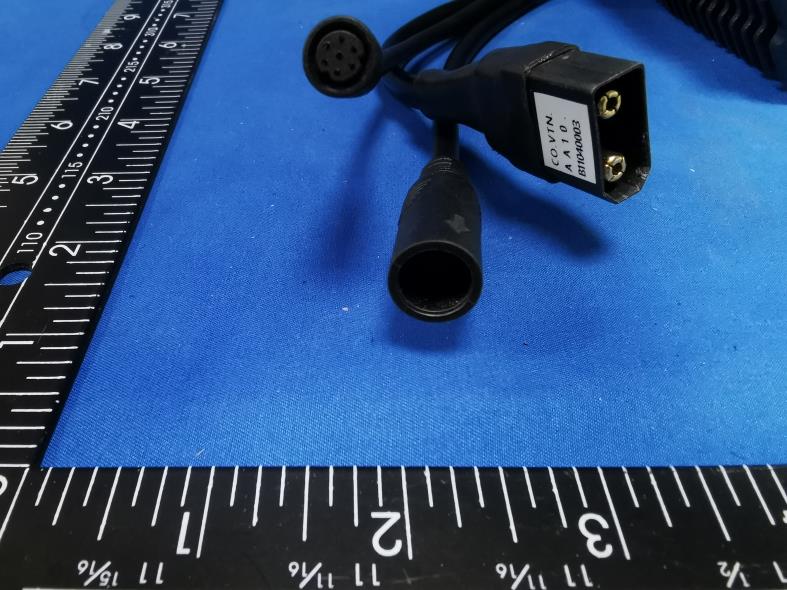
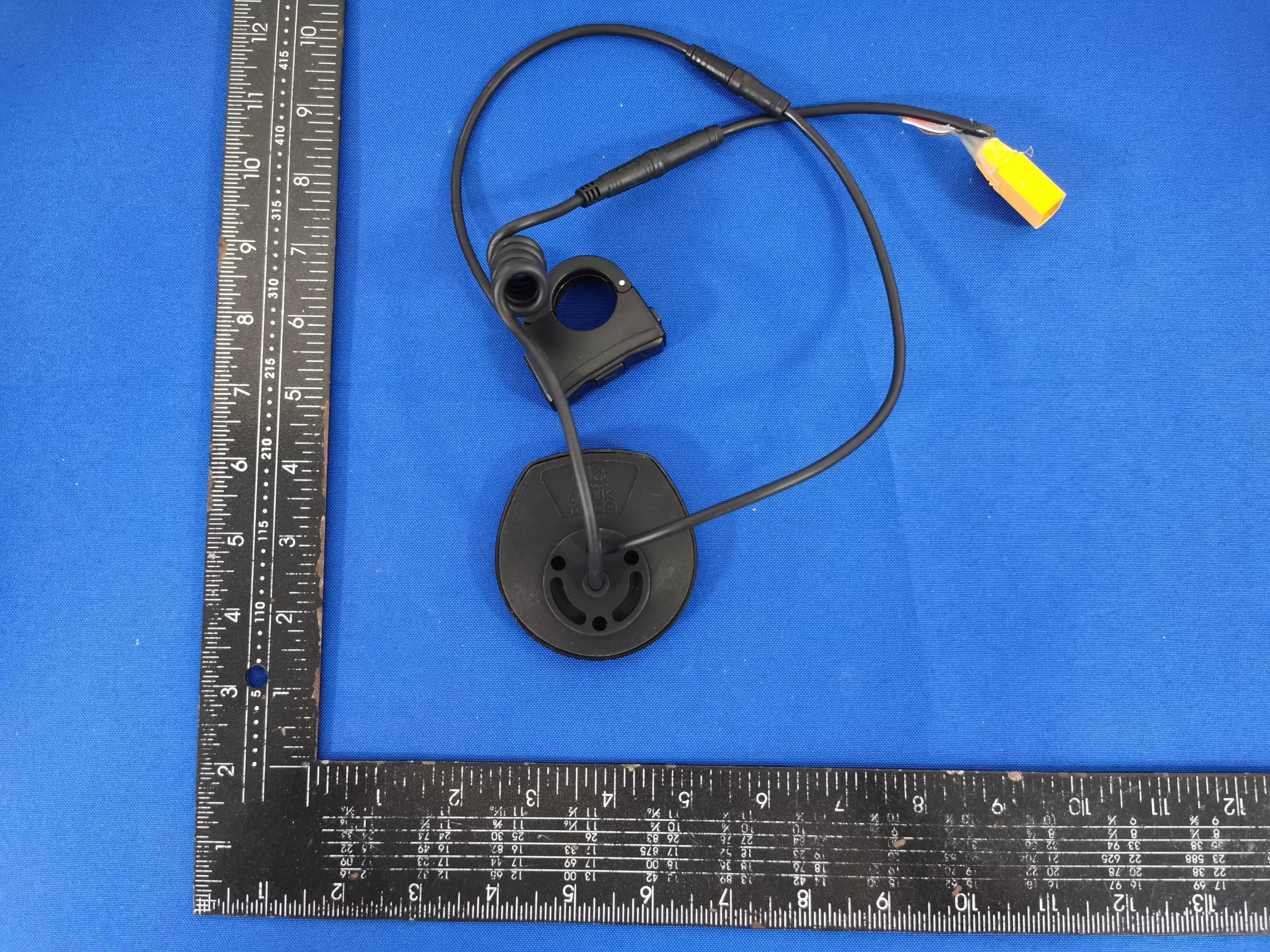
FCC: 2A9XP-PHOTON External Photos of the EUT FCC: 2A9XP-PHOTON FCC: 2A9XP-PHOTON FCC: 2A9XP-PHOTON

ID Label/Location Info

Label and Location Size: L: 3.0cm*W: 2.0cm Label and Location Model No.: Photon FCC ID : 2A9XP-PHOTON

Internal Photos

FCC: 2A9XP-PHOTON Internal Photos of the EUT FCC: 2A9XP-PHOTON FCC: 2A9XP-PHOTON FCC: 2A9XP-PHOTON Antenna FCC: 2A9XP-PHOTON

RF Exposure Info

RF Exposure evaluation FCC: 2A9XP-PHOTON Exposure category: General population/uncontrolled environment EUT Type: Production Unit Device Type: Mobile Device 1. Reference According to §1.1307(b)(1), systems operating under the provisions of this section shall be operated in a manner that ensures that the public is not exposed to radio frequency energy level in excess of the Commission’s guidelines. According to §1.1310 and §2.1091 RF exposure is calculated. KDB447498 D01: Mobile and Portable Devices RF Exposure Procedures and Equipment Authorization Policies 2. Limit Limits for Maximum Permissible Exposure (MPE)/Controlled Exposure Frequency Range(MHz) Electric Field Strength(V/m) Magnetic Field Strength(A/m) Power Density (mW/cm²) Averaging Time (minute) Limits for Occupational/Controlled Exposure 0.3 – 3.0 3.0 – 30 30 – 300 300 – 1500 1500 – 100,000 614 1842/f 61.4 / / 1.63 4.89/f 0.163 / / (100) * (900/f 2 )* 1.0 f/300 5 6 6 6 6 6 Limits for Maximum Permissible Exposure (MPE)/Uncontrolled Exposure Frequency Range(MHz) Electric Field Strength(V/m) Magnetic Field Strength(A/m) Power Density (mW/cm²) Averaging Time (minute) Limits for Occupational/Controlled Exposure 0.3 – 3.0 3.0 – 30 30 – 300 300 – 1500 1500 – 100,000 614 824/f 27.5 / / 1.63 2.19/f 0.073 / / (100) * (180/f 2 )* 0.2 f/1500 1.0 30 30 30 30 30 F=frequency in MHz *=Plane-wave equivalent power density 3. MPE Calculation Method Predication of MPE limit at a given distance Equation from page 18 of OET Bulletin 65, Edition 97-01 S=PG/4πR² Where: S=power density P=power input to antenna G=power gain of the antenna in the direction of interest relative to an isotropic radiator R=distance to the center of radiation of the antenna 4. Antenna Information Photon can only use antennas certificated as follows provided by manufacturer; Antenna No. Model No. of antenna: Type of antenna: Gain of the antenna (Max.) Frequency range: BT / PCB Antenna 1.5dBi for 2400-2500MHz; 5. Manufacturing Tolerance BLE GFSK(Peak) Channel Channel 00 Channel 19 Channel 39 Target (dBm) -3.0 -3.0 -2.0 Tolerance ±(dB) 1.0 1.0 1.0 6. Standalone MPE Result As declared by the Applicant, the EUT is a wireless device used in a fix application, at least 20 cm from any body part of the user or nearby persons; from the maximum EUT RF output power, the minimum separation distance, r =20cm, as well as the gain of the used antenna is 1.5dBi, the RF power density can be obtained. Modulation Type Output power Antenna Gain (dBi) Antenna Gain (linear) MPE (mW/cm 2 ) MPE Limits (mW/cm 2 ) dBm mW BLE -1.0 0.7943 1.5 1.4125 0.0002 1.0000 Remark: 1. Output power (Peak) including turn-up tolerance; 2. MPE evaluate distance is 20cm from user manual provide by manufacturer. 7. Conclusion The measurement results comply with the FCC Limit per 47 CFR 2.1091 for the uncontrolled RF Exposure of mobile device. ----------------THE END OF REPORT---------------

Test Report

1. Antenna Description: Antenna type PCB Antenna Model Photon Frequency range 2400-2500MHz Manufacturer CYC Motor Limited ANT Peak Gain 1.50 dBi 2. Antenna Photo: 3. Test Equipment & Conditions 3.1 Test instrument VSWR is tested using Agilent E5071B connected to a hand mechanism, and the status is free space. 3.2 Test environment and methods 4.Antenna Radiation Pattern 2400MHz 2450MHz 2500MHz

Test Setup Photos

FCC: 2A9XP-PHOTON Test Setup Photos of the EUT

Contact Information

Applicant

Doris Chan
[email protected]36908938Fax: /

Test Firm

SHENZHEN CTA TESTING TECHNOLOGY CO., LTD.Eric Wang
[email protected]+86 755 2322 5875

Technical Specifications

#Rule PartsFrequency RangePower Output
115C2.40 GHz - 2.48 GHz500.00 µW
Confidentiality
Long Term
Grant Notes
Output Power listed is peak conducted. RF exposure compliance is addressed for 1.1310 and 2.1091 MPE limits. The antenna(s) used for this transmitter must be installed to provide a separation distance of at least 20 cm from all persons. End Users must be provided with transmitter operation conditions for satisfying RF exposure compliance.

Other Applications from CYC Motor Limited

INTUITION display - FCC ID 2A9XP-ID001 - CYC Motor Limited
2A9XP-ID001

INTUITION display

Sep 24, 2023

Equipment Class

DTS - Digital Transmission System