FCCID.CO- FCC ID Database
HomeCompaniesEquipment ClassesSearch

© 2026 FCC ID Database. All rights reserved.

AboutContactData sourced from FCC public records
  1. Home/
  2. ARB Corporation Ltd/
  3. 2AA2H-LINXTPMS1

2AA2H-LINXTPMS1LINX TPMS Module

ARB Corporation Ltd
LINX TPMS Module - FCC ID 2AA2H-LINXTPMS1 - ARB Corporation Ltd
Click to zoom

Application Details

Equipment Class
DTS - Digital Transmission System
Date of Grant
Feb 25, 2020
Application Purpose
Original Equipment
Date of Application
Feb 25, 2020
Equipment Note
LINX TPMS Module
Frequency Range
2402.00000000 - 2480.00000000
Company
ARB Corporation Ltd
Country
Australia

Documents & Files

Select a file to view

Users Manual

↗

Cover Letter(s)

↗
↗

External Photos

↗

ID Label/Location Info

↗

Internal Photos

↗

RF Exposure Info

↗

Test Report

↗

Test Setup Photos

↗

Document Text

Text extracted from the exhibit documents filed with the FCC. Open a document above to read the original.

Users Manual

LINX TPMS MODULE Part Number: 7450116 Latest Revision Date: 01/04/2019 Page 1 of 2 Fitting Instruction Number: 3789891 QUICK START GUIDE This module enables communication between ARB LINX and the ARB TPMS sensors. Installation The LINX TPMS Module should be positioned in a fairly central location in the vehicle, equidistant for all wheels. This will ensure the best performance from all TPMS tyre sensors. Under the armrest centre console is a good location. It is a central location and in most vehicles it also has 12VDC outlet which can be used to power the module. The LINX TPMS module should be secured in place using at least one of the screw holes or using cable ties. Test for a 12VDC circuit that turns on when the vehicle key is in the ACC or ON position. The circuit must also be off when the vehicle key is in the off position, hence not a permanent battery connection or else the module will continue to draw power from the vehicle battery when the vehicle is turned off. Connect the RED wire to this circuit using a suitable method such as an insulated wire tap, or a solder and tap. A 12VDC power outlet or cigarette lighter socket provides this functionality and is the ideal place to piggy back power from. Connect the BLACK wire to the vehicle ground. Connection to LINX To connect the LINX TPMS module to LINX, turn the vehicle key to the ACC position so that both the TPMS module and LINX are on. Navigate LINX to the main icon screen and activate the TPMS module. In the TPMS module settings screen, tap the ‘Connect to TPMS’ button, and select your TPMS module from the list. When connected the vehicle icon on the TPMS module will be highlighted as shown. To learn the TPMS tyre sensors that are associated to your vehicle follow the instructions in the latest LINX Operation Guide. LINX TPMS MODULE Part Number: 7450116 Latest Revision Date: 01/04/2019 Page 2 of 2 Fitting Instruction Number: 3789891 ARB PRODUCTS WARRANTY AGAINST DEFECTS ARB warrants the ARB Products against defects in workmanship and materials for the Warranty Period. If defective workmanship or materials become apparent in the Warranty Period, ARB will replace or repair the defective Product. The benefits to the customer given by this warranty are in addition to other rights and remedies of the customer under a law in relation to the goods or services to which the warranty relates. 1) In this warranty: • ARB means ARB Corporation Limited (ABN 31 006 708 756) of 42-44 Garden St, Kilsyth Victoria 3137 • ARB Outlet means an outlet which has been authorised by ARB to sell and fit ARB Products • ARB Product means products which ARB manufacturers or for which ARB is the exclusive supplier • Product Information means the information about the relevant ARB Product which may be contained in any of: documentation provided with the ARB Product, owner’s manual, operating manual, service manual or the manufacturer’s manual or labels attached to the ARB Product • Warranty Period means, in respect of an ARB Product, the period that this warranty against defects applies and which is set out in paragraph 8. 2) To be entitled to claim the warranty, the customer must: a) have the ARB Product fitted in accordance with the Product Information b) carry out normal care and maintenance of the ARB Product, including any required by the Product Information c) provide proof of purchase of the ARB Product d) make the claim in the Warranty Period. 3) The warranty will not apply in circumstances where the defect is caused by: a) unusual, improper or negligent use or misuse of the ARB Product b) incorrect fitting of the ARB Product other than at an ARB Outlet c) use of non-genuine ARB components in or with the ARB Product d) use of the ARB Product outside of the requirements of the Product Information. 4) The procedure for the customer to claim the warranty is: a) return the ARB Product to the nearest ARB Outlet or contact ARB to arrange a time to bring a vehicle fitted with the ARB Product to an ARB Outlet for inspection. Contact details are in paragraph 7 below if further information is required regarding local outlet details b) bring proof of purchase of the ARB Product to the ARB Outlet c) ARB will review the ARB Product and advise whether the conditions of this warranty have been met 5) Where ARB accepts a customer’s warranty claim, ARB will rectify any defective workmanship or materials at its own expense. 6) Expenses incurred by the customer in claiming the warranty are to be borne by the customer. 7) This warranty is given by: ARB Corporation Limited 42-44 Garden Street Kilsyth VIC 3137, Australia. Phone: 03 9761 6622. Fax: 03 9721 9090. www.arb.com.au 8) The period within which a defect in the ARB Products must appear if the customer is to be entitled to claim the warranty is 3 years starting on the date of purchase unless: The ARB Product is used in Commercial Use. Commercial Use means use in industry or commerce including (without limitation) use in the mining industry or as a hire vehicle. In this case, the Warranty Period is 1 year 9) The warranty against defects contained in this document replaces any other warranty against defects or voluntary warranty given in relation to the Products. Our goods come with guarantees that cannot be excluded under the Australian Customer Law. You are entitled to a replacement or refund for a major failure and compensation for any other reasonably foreseeable loss or damage. You are also entitled to have the goods repaired or replaced if the goods fail to be of acceptable quality and the failure does not amount to a major failure. USA - FCC Statement This device complies with part 15 of the FCC Rules. Operation is subject to the following two conditions: (1) this device may not cause harmful interference, and (2) this device must accept any interference received, including interference that may cause undesired operation. This equipment has been tested and found to comply with the limits for a Class B digital d…

Text truncated - open the document above for the full version.

External Photos

Page 1 / 8 Report No.: T191231N01 Ref. No.: Rev. 00 External Photo (Model: 7450116) Page 2 / 8 Report No.: T191231N01 Ref. No.: Rev. 00 Page 3 / 8 Report No.: T191231N01 Ref. No.: Rev. 00

ID Label/Location Info

LINX TPMS COMMS BOX Diagram 7450116 Label location

Internal Photos

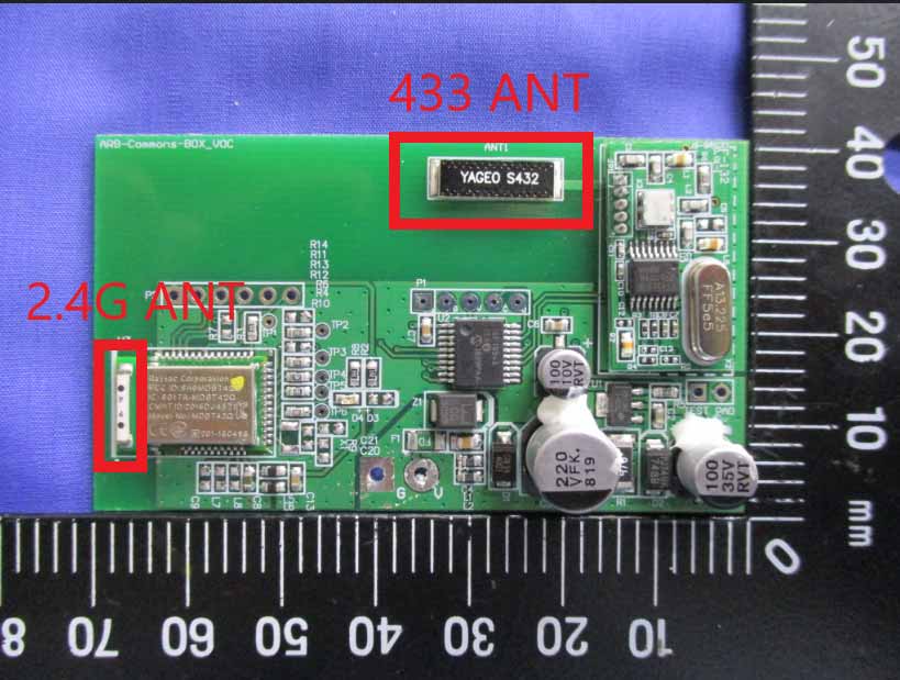
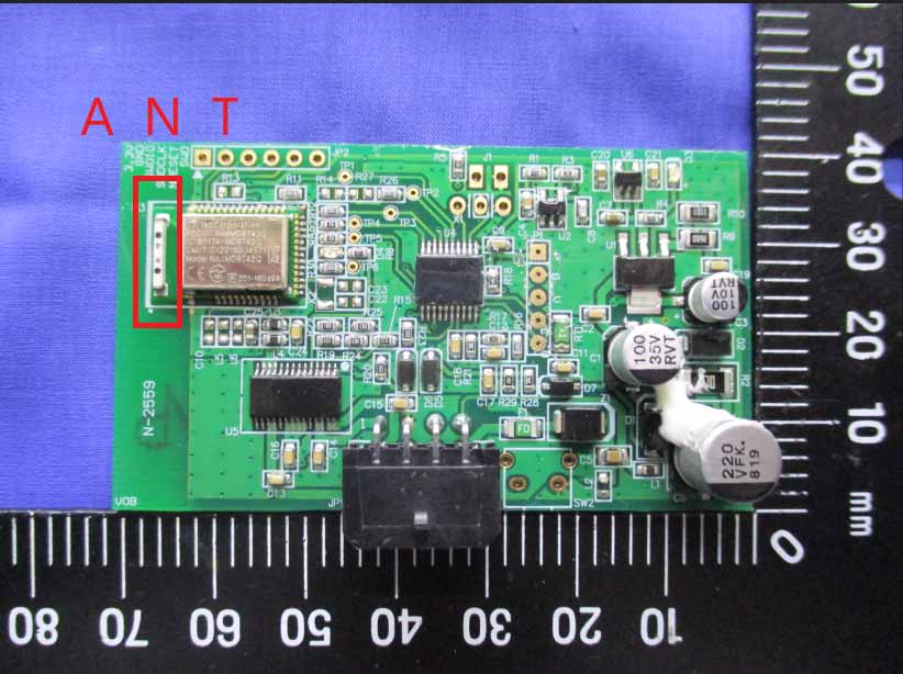
Page 4 / 8 Report No.: T191231N01 Ref. No.: Rev. 00 Internal Photo (Model: 7450116) Page 5 / 8 Report No.: T191231N01 Ref. No.: Rev. 00 Page 6 / 8 Report No.: T191231N01 Ref. No.: Rev. 00 Page 7 / 8 Report No.: T191231N01 Ref. No.: Rev. 00 Page 8 / 8 Report No.: T191231N01 Ref. No.: Rev. 00 32MHz

RF Exposure Info

FCC ID.: 2AA2H-LINXTPMS1 Page: 1 / 7 Report No.: T191231N01-MF Rev.: 01 No.11, Wugong 6th Rd., Wugu Dist., New Taipei City 24891, Taiwan / 新北市五股區五工六路11號 t:(886-2) 2299-9720 f:(886-2) 2298-1882 www.sgs.tw www.ccsrf.com IEEE C95.1 KDB 447498 D03 47 C.F.R. Part 1, Subpart I, Section 1.1310 47 C.F.R. Part 2, Subpart J, Section 2.1091 RF EXPOSURE REPORT For LINX TPMS Module Model: 7450116 Data Applies To: N/A Trade Name: Issued to ARB Corporation Ltd. 42-44 Garden St. Kilsyth, Victoria, Australia, 3137 Issued By Compliance Certification Services Inc. No.11, Wugong 6th Rd., Wugu Dist., New Taipei City 24891, Taiwan. (R.O.C.) Issued Date: February 20, 2020 Page: 2 / 7 Report No.: T191231N01-MF Ref. No.: Rev.: 01 REVISION HISTORY Rev. Issue Date Revisions Effect Page Revised By 00 February 10, 2020 Initial Issue ALL Angel Cheng 01 February 20, 2020 See the following note rev.01 ALL Angel Cheng Note: ※ Rev.00 Issue Date: February 10, 2020 Original Report ※ Rev.01 Issue Date: February 20, 2020 Revise EUT Specification & Maximum Permissible Exposure. Page: 3 / 7 Report No.: T191231N01-MF Ref. No.: Rev.: 01 TABLE OF CONTENTS 1. LIMIT .......................................................................................................................................... 4 2. EUT SPECIFICATION ....................................................................................................... 5 3. TEST RESULTS ................................................................................................................... 6 4. MAXIMUM PERMISSIBLE EXPOSURE ................................................................... 7 Page: 4 / 7 Report No.: T191231N01-MF Ref. No.: Rev.: 01 1. TEST RESULT CERTIFICATION We hereby certify that: The equipment has been tested by Compliance Certification Services Inc., and found compliance with the requirement of the applicable standards. The test record, data evaluation and Equipment under Test (EUT) configurations represented herein are true and accurate accounts of the measurement of the sample’s RF characteristics under the conditions specified in this report. APPLICABLE STANDARDS STANDARD TEST RESULT IEEE C95.1 2005 KDB 447498 D03 47 C.F.R. Part 1, Subpart I, Section 1.1310 47 C.F.R. Part 2, Subpart J, Section 2.1091 No non-compliance noted Statements of Conformity Determining compliance shall be based on the results of the compliance measurement, not taking into account measurement instrumentation uncertainty. Approved by: Kevin Tsai Deputy Manager Compliance Certification Services Inc. Page: 5 / 7 Report No.: T191231N01-MF Ref. No.: Rev.: 01 2. LIMIT According to §15.247(i), systems operating under the provisions of this section shall be operated in a manner that ensures that the public is not exposed to radio frequency energy levels in excess of the Commission's guidelines. See § 1.1307(b)(1) of this chapter. 3. EUT SPECIFICATION EUT LINX TPMS Module Model 7450116 Brand RF Module RAYTAC Model: MDBT42Q-AT Frequency band (Operating) 802.11b/g/n HT20: 2412MHz ~ 2462MHz 802.11n HT40: 2422MHz ~ 2452MHz Others 2402MHz ~ 2480MHz (BT 4.0) Device category Portable (<20cm separation) Mobile (>20cm separation) Others Exposure classification Occupational/Controlled exposure (S = 5mW/cm 2 ) General Population/Uncontrolled exposure (S=1mW/cm 2 ) Antenna Specification Multilayer Chip Antenna / Gain: -1.6 dBi (Numeric gain: 0.69) worst Maximum Output power GFSK(4.2) 2.01 dBm (1.589 mW) Maximum Average output power GFSK(4.2) 1.82 dBm (1.521 mW) Maximum Tune up Power GFSK(4.2) 2.50 dBm (1.778 mW) Evaluation applied MPE Evaluation* SAR Evaluation N/A Reported Date February 03, 2020 Page: 6 / 7 Report No.: T191231N01-MF Ref. No.: Rev.: 01 4. TEST RESULTS No non-compliance noted. Calculation Given d GP E  = 30 & 377 2 E S= Where E = Field strength in Volts / meter P = Power in Watts G = Numeric antenna gain d = Distance in meters S = Power density in milliwatts / square centimeter Combining equations and re-arranging the terms to express the distance as a function of the remaining variables yields: 2 377 30 d GP S  = Changing to units of mW and cm, using: P (mW) = P (W) / 1000 and d (cm) = d(m) / 100 Yields () () 22 0796.0 100/377 1000/30 d GP d GP S  =   = Equation 1 Where d = Distance in cm P = Power in mW G = Numeric antenna gain S = Power density in mW / cm 2 Page: 7 / 7 Report No.: T191231N01-MF Ref. No.: Rev.: 01 5. MAXIMUM PERMISSIBLE EXPOSURE Substituting the MPE safe distance using d = 20 cm into Equation 1: GPS=000199.0 Where P = Power in mW G = Numeric antenna gain S = Power density in mW / cm 2 GFSK(4.2): Ch. Frq.(MHz) P (mW) Gain (num.) D (cm) Power density in mW / cm 2 Limit (mW/cm2) Result High 2480 1.778 0.69 20 0.0002 1 Pass

Test Report

FCC ID: 2AA2H-LINXTPMS1 Page: 1 / 60 Report No.: T191231N01-RP1 Rev.: 02 No.8, Jiucengling, Xinhua District, Tainan City 712, Taiwan / 71249 8 t:(886-6) 5802-201 f:(886-6) 5802-202 www.sgs.tw www.ccsrf.com FCC 47 CFR PART 15 SUBPART C AND ANSI C63.10: 2013 TEST REPORT For LINX TPMS Module Model: 7450116 Brand: Issued for ARB Corporation Ltd. 42-44 Garden St. Kilsyth, Victoria, Australia, 3137 Issued by Compliance Certification Services Inc. Tainan Lab. No.8,Jiucengling, Xinhua Dist., Tainan City 712, Taiwan (R.O.C.) TEL: 886-6-580-2201 FAX: 886-6-580-2202 Issued Date: February 26, 2020 Note: This report shall not be reproduced except in full, without the written approval of Compliance Certification Services Inc. Ltd. This document may be altered or revised by Compliance Certification Services Inc. personnel only, and shall be noted in the revision section of the document Page: 2 / 60 Re port No.: T191231N01-RP1 Ref. No.: Rev.: 02 REVISION HISTORY Rev. Issue Date Revisions Effect Page Revised By 00 February 13, 2020 Initial Issue ALL Gina Lin 01 February 25, 2020 See the following note rev.01 ALL Gina Lin 02 February 26, 2020 See the following note rev.02 Page10 Gina Lin Note: Rev.00 Issue Date: February 13, 2020 Original Report Rev.01 Issue Date: February 25, 2020 Revise typo & Measurement Equipment & Average Power & Test Procedure. Rev.02 Issue Date: February 26, 2020 Revise Measurement Equipment. Page: 3 / 60 Re port No.: T191231N01-RP1 Ref. No.: Rev.: 02 TABLE OF CONTENTS 1. TEST REPORT CERTIFICATION ......................................................................................... 4 2. TEST RESULT SUMMARY ................................................................................................... 5 3. EUT DESCRIPTION ............................................................................................................... 6 3.1 DESCRIPTION OF EUT & POWER ................................................................................................. 6 4. DESCRIPTION OF TEST MODES......................................................................................... 7 5. TEST METHODOLOGY ......................................................................................................... 8 6. FACILITIES AND ACCREDITATIONS .................................................................................. 8 6.1 FACILITIES ...................................................................................................................................... 8 6.2 EQUIPMENT .................................................................................................................................... 8 6.3 LABORATORY ACCREDITATIONS LISTINGS ............................................................................... 8 6.4 TABLE OF ACCREDITATIONS AND LISTINGS ............................................................................. 9 7. CALIBRATION AND UNCERTAINTY ................................................................................. 10 7.1 MEASURING INSTRUMENT CALIBRATION ................................................................................ 11 7.2 MEASUREMENT UNCERTAINTY ................................................................................................. 11 8. SETUP OF EQUIPMENT UNDER TEST ............................................................................. 12 8.1 SETUP CONFIGURATION OF EUT .............................................................................................. 12 8.2 SUPPORT EQUIPMENT ................................................................................................................ 13 8.3 EUT OPERATING CONDITION ..................................................................................................... 14 9. APPLICABLE LIMITS AND TEST RESULTS ..................................................................... 15 9.1 6dB BANDWIDTH .......................................................................................................................... 15 9.2 MAXIMUM PEAK OUTPUT POWER ............................................................................................. 19 9.3 DUTY CYCLE ................................................................................................................................. 25 9.4 POWER SPECTRAL DENSITY ..................................................................................................... 29 9.5 CONDUCTED SPURIOUS EMISSION .......................................................................................... 33 9.6 RADIATED EMISSIONS ................................................................................................................ 39 9.7 POWERLINE CONDUCTED EMISSIONS ..................................................................................... 53 10. ANTENNA REQUIREMENT .............................................................................................. 55 10.1 STANDARD APPLICABLE ........................................................................................................... 55 10.2 ANTENNA CONNECTED CONSTRUCTION ............................................................................... 55 APPENDIX I SETUP PHOTOS ................................................................................................ 56 Page: 4 / 60 Re port No.: T191231N01-RP1 Ref. No.: Rev.: 02 1. TEST REPORT CERTIFICATION Applicant ARB Corporation Ltd. 42-44 Garden St. Kilsyth, Victoria, Australia, 3137 Manufacturer Vision Automobile Electronics Industrial Co Ltd. No.78, Gongye 3rd Rd., Technology Industrial Park, Tainan, Taiwan, 70955 Equipment Under Test LINX TPMS Module Model Number 7450116 Brand Name Date of Test January 07, 2020 ~ January 16, 2020 APPLICABLE STANDARD STANDARD TEST RESULT FCC Part 15 Subpart C AND ANSI C63.10: 2013 No non-compliance noted Statements of Conformity Determining compliance shall be based on the results of the compliance measurement, not ta…

Text truncated - open the document above for the full version.

Test Setup Photos

Page: 56 / 60 Re port No.: T191231N01-RP1 Ref. No.: Rev.: 01 APPENDIX I SETUP PHOTOS RADIATED EMISSION MEASUREMENT SETUP Below 1GHz Page: 57 / 60 Re port No.: T191231N01-RP1 Ref. No.: Rev.: 01 Page: 58 / 60 Re port No.: T191231N01-RP1 Ref. No.: Rev.: 01 RADIATED RF MEASUREMENT SETUP Above 1GHz Page: 59 / 60 Re port No.: T191231N01-RP1 Ref. No.: Rev.: 01 RF CONDUCTED SETUP Page: 60 / 60 Re port No.: T191231N01-RP1 Ref. No.: Rev.: 01 CONDUCTED EMISSION MEASUREMENT SETUP

Contact Information

Applicant

James Luke(Mr)
[email protected]+63197616622Fax: +61397616807

Technical Contact

Compliance Certification Services IncDaphne Liang
[email protected]886 6 580 2201

No.8, Jiucengling, Xinhua Dist. · Tainan · Taiwan

Non-Technical Contact

Compliance Certification Services IncDaphne Liang
[email protected]886 6 580 2201

Test Firm

Compliance Certification Services Inc. Tainan Lab.Tommy Wu
[email protected]+886 2-2299-3270Fax: +886-2-2299-1882

Technical Specifications

#Rule PartsFrequency RangePower Output
115C2.40 GHz - 2.48 GHz1.60 mW
Confidentiality
Long Term
Grant Notes
Power output listed is conducted. The antenna used for this transmitter must be installed to provide a separation distance of at least 20 cm from all persons and must not be co-located or operating in configuration with any other antenna or transmitter. End-users must be provided with antenna installation and transmitter operating conditions for satisfying RF exposure compliance.

Other Applications from ARB Corporation Ltd
Pressure Control Module - FCC ID 2AA2H-PCM1 - ARB Corporation Ltd
2AA2H-PCM1

Pressure Control Module

Jul 27, 2020

Equipment Class

DTS - Digital Transmission System