Text extracted from the exhibit documents filed with the FCC. Open a document above to read the original.
PRESSURE CONTROL MODULE Part Number: 0830001 QUICK START GUIDE ARB Pressure Control provides the capability to inflate/deflate tyres and other inflatable accessories to a user settable pressure. It can be quickly and easily fitted to an ARB compressor, and can be controlled using the ARB Pressure Control App, which is available for download from Google Play and Apple App store. The kit contains: - ARB PCM (Pressure Control Module). This is the brains of the kit, communicating with the smartphone app, pressure sensor and activating the solenoid valves to control the inflation/deflation. - ARB PRV (Pressure Regulating Valve) - ARB pressure sensor - wiring harness PCM Wiring Harness PRV Pressure Sensor To connect an ARB hose for tyre inflation the following hardware is also required: - ARB Remote Hose Coupling Mount Kit (#171314) - Reinforced hose (range of lengths from 0.3 to 3.0m, #0740201 – 06) - 1/8 BSP to JIC-4 adapter fitting (#0740105), for connecting the reinforced hose to the PRV. Installation The PRV can be screwed directly into the compressor manifold 1/8 BSP port. Or it can be remotely mounted from the compressor on a manifold kit (#171503). The PCM should be positioned high in the engine bay, or inside the vehicle cabin, within 1m [3ft] of the PRV for wiring connection. Avoid very hot areas such as the exhaust. The PCM is water resistant, but should be orientated with the opening facing downwards to avoid water accumulating inside the module. Also avoid very confined spaces that might impact on the Bluetooth connection with the smartphone app. 1. One of the PRV input ports (inward pointing arrows) comes with a 1/8 BSP fitting pre- installed with sealant, screw it into one of the 1/8 BSP ports on your compressor manifold, or alternate compressed air supply. If desired the pre-installed nipple can be relocated to the other input port on the opposite side of the PRV. Note: Always use thread sealant or PTFE tape to seal all tapered threaded joints. O- ring sealed parallel threaded joints do not require sealant or tape. Latest Revision Date: 09/06/2020 Page 1 of 7 PRESSURE CONTROL MODULE Part Number: 0830001 2. Install the pressure sensor into a regulated output port (outward pointing arrows) of the PRV. Any of the PRV regulated output ports may be used, select the regulated output port that best suits your installation configuration. 3. Attach the two connectors of the wiring harness to the two solenoid coils of the PRV. Note that the connector with the purple wire should be matched only with the deflate valve coil (shown on the right directly opposite to the exhaust fitting). Retain the connectors using the supplied screws. 4. Attach the sensor connector of the wiring harness to the pressure sensor by inserting it until it clicks in. 5. Route the wiring harness to the desired PCM mounting location, and plug in the connector until it clicks. Secure the wiring with cable ties making sure not to leave the wires under tension. Fix the PCM in position using the screw tabs provided. Fixing with double sided tape or cable ties would also be acceptable. 6. Connect the ring terminal (black wire) to a body ground. 7. The PCM red wire is intended to be connected to the ARB compressor switch so that the PCM is powered only when the compressor switch is turned on. To do this, remove the compressor harness red wire terminal from the rear of the compressor switch, and connect the PCM piggyback quick connect terminal in its place. Then re connect the compressor harness red wire terminal to the PCM piggyback terminal. Alternatively, it can be connected to the pressure switch terminal with the red wire. Protect this 12V wire with split conduit and secure with cable ties. Note: the red wire provides 12V power to the PCM. Connect it to a 12VDC circuit that is powered on when the compressor is switched on. The circuit must also be off when the vehicle key is in the off position, hence not a permanent battery connection or else the module will continue to draw power from the vehicle battery when the vehicle is turned off. Latest Revision Date: 09/06/2020 Page 2 of 7 PRESSURE CONTROL MODULE Part Number: 0830001 8. Connect the Remote Hose Coupling Mount Kit (171314) to a regulated output port of the PRV. Any of the PRV regulated output ports may be used, select the regulated output port that best suits your installation configuration. If the PRV is installed and connected as described above, the finished assembly should look like this. Latest Revision Date: 09/06/2020 Page 3 of 7 PRESSURE CONTROL MODULE Part Number: 0830001 Smartphone App The ARB Pressure Control App can be downloaded from the Google Play Store or Apple App Store. Search for “Pressure Control”. To connect to the PCM it must be powered on. So if wired as described earlier, turn on your vehicle ignition and switch on the compressor. Follow these steps to connect the app to the PCM for the first time. After opening the app the first step is to connect to your PCM. Tap the settings icon. Tap “Connect to Pressure Control” When the app is disconnect from the PCM most features are unavailable and are greyed out. The app will search for your PCM. When found tap “CONNECT TO PRESSURE CONTROL MODULE”. When more than one PCM is found, if you know the name of your PCM then select it before tapping “CONNECT TO PRESSURE CONTROL MODULE”. Otherwise make sure your PCM is the only one with about 20m that is turned on, then try again. Latest Revision Date: 09/06/2020 Page 4 of 7 PRESSURE CONTROL MODULE Part Number: 0830001 When connect the app appearance will change, allowing interaction with all the features. The settings screen features are: - tap underlined text to enter preset names and pressures, - change pressure readout units, - select ‘Power On Mode’ (the pressure control mode that the PCM starts in each time it is powered on), - turn the audible alert on and off (sounds each time a pressure adjustment is complete), - select the ‘Allow Only If Engin…
Text truncated - open the document above for the full version.
Page 1 / 6 Report No.: T200701N04 Ref. No.: Rev. 00 External Photo (Model: 0830001) Page 2 / 6 Report No.: T200701N04 Ref. No.: Rev. 00
Pressure Control Module Diagram 0830001 Model: 0830001 FCC ID: 2AA2H-PCM1 Label location
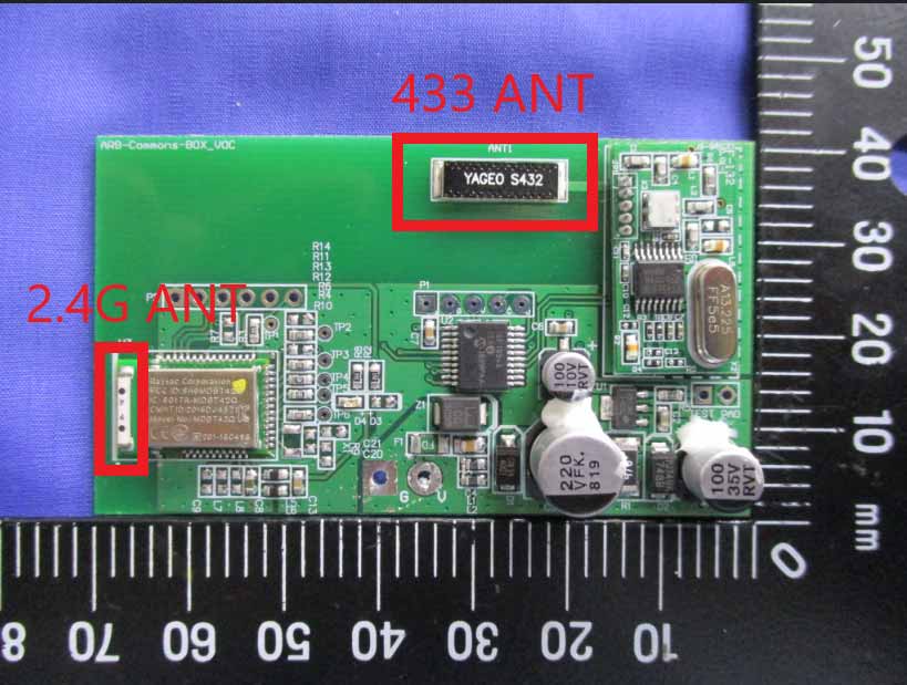
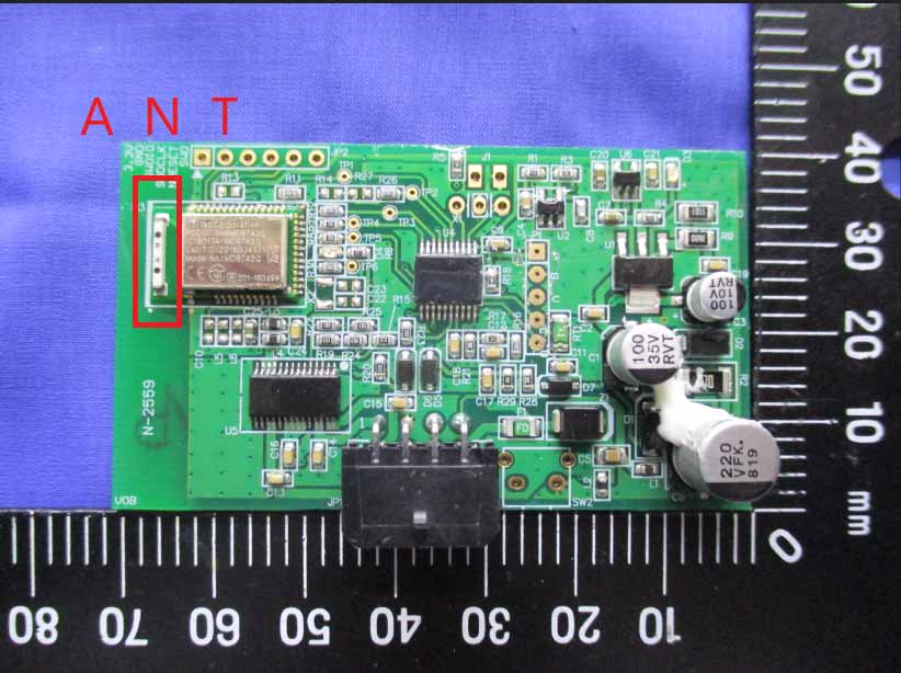
Page 3 / 6 Report No.: T200701N04 Ref. No.: Rev. 00 Internal Photo (Model: 0830001) Page 4 / 6 Report No.: T200701N04 Ref. No.: Rev. 00 Page 5 / 6 Report No.: T200701N04 Ref. No.: Rev. 00 Page 6 / 6 Report No.: T200701N04 Ref. No.: Rev. 00
FCC ID: 2AA2H-PCM1 Page: 1 / 7 Report No.: T200701N04-MF Rev.: 00 No.11, Wugong 6th Rd., Wugu Dist., New Taipei City 24891, Taiwan / 新北市五股區五工六路11號 t:(886-2) 2299-9720 f:(886-2) 2298-1882 www.sgs.tw www.ccsrf.com Unless otherwise stated the results shown in this test report refer only to the sample(s) tested and such sample(s) are retained for 90 days only. 除非另有說明,此報告結果僅對測試之樣品負責,同時此樣品僅保留90天。本報告未經本公司書面許可,不可部份複製。 This document is issued by the Company subject to its General Conditions of Service printed overleaf, available on request or accessible at http://www.sgs.com.tw/Terms-and-Conditions and, for electronic format documents, subject to Terms and Conditions for Electronic Documents at http://www.sgs.com.tw/Terms-and-Conditions. Attention is drawn to the limitation of liability, indemnification and jurisdiction issues defined therein. Any holder of this document is advised that information contained hereon reflects the Company’s findings at the time of its intervention only and within the limits of client’s instruction, if any. The Company’s sole responsibility is to its Client and this document does not exonerate parties to a transaction from exercising all their rights and obligations under the transaction documents. This document cannot be reproduced, except in full, without prior written approval of the Company. Any unauthorized alteration, forgery or falsification of the content or appearance of this document is unlawful and offenders may be prosecuted to the fullest extent of the law. Compliance Certification Services Inc. 程智科技股份有限公司 Member of the SGS Group IEEE C95.1 KDB 447498 D03 47 C.F.R. Part 1, Subpart I, Section 1.1310 47 C.F.R. Part 2, Subpart J, Section 2.1091 RF EXPOSURE REPORT For Pressure Control Module Model: 0830001 Data Applies To: N/A Trade Name: Issued to ARB Corporation Ltd. 42-44 Garden St. Kilsyth, Victoria, Australia, 3137 Issued By Compliance Certification Services Inc. No.11, Wugong 6th Rd., Wugu Dist., New Taipei City 24891, Taiwan. (R.O.C.) Issued Date: July 20, 2020 Page: 2 / 7 Report No.: T200701N04-MF Ref. No.: Rev.: 00 REVISION HISTORY Rev. Issue Date Revisions Effect Page Revised By 00 July 20, 2020 Initial Issue ALL Angel Cheng 01 July 10, 2020 See the following note rev.01 ALL Angel Cheng Note: ※ Rev.00 Issue Date: February 10, 2020 Original Report ※ Rev.01 Issue Date: July 10, 2020 Revise EUT Specification & Maximum Permissible Exposure. Page: 3 / 7 Report No.: T200701N04-MF Ref. No.: Rev.: 00 TABLE OF CONTENTS 1. LIMIT .......................................................................................................................................... 4 2. EUT SPECIFICATION ....................................................................................................... 5 3. TEST RESULTS ................................................................................................................... 6 4. MAXIMUM PERMISSIBLE EXPOSURE ................................................................... 7 Page: 4 / 7 Report No.: T200701N04-MF Ref. No.: Rev.: 00 1. TEST RESULT CERTIFICATION We hereby certify that: The equipment has been tested by Compliance Certification Services Inc., and found compliance with the requirement of the applicable standards. The test record, data evaluation and Equipment under Test (EUT) configurations represented herein are true and accurate accounts of the measurement of the sample’s RF characteristics under the conditions specified in this report. APPLICABLE STANDARDS STANDARD TEST RESULT IEEE C95.1 2005 KDB 447498 D03 47 C.F.R. Part 1, Subpart I, Section 1.1310 47 C.F.R. Part 2, Subpart J, Section 2.1091 No non-compliance noted Statements of Conformity Determining compliance shall be based on the results of the compliance measurement, not taking into account measurement instrumentation uncertainty. Approved by: Reporter: Kevin Tsai Angel Cheng Deputy Manager Report coordinator Compliance Certification Services Inc. Compliance Certification Services Inc. Page: 5 / 7 Report No.: T200701N04-MF Ref. No.: Rev.: 00 2. LIMIT According to §15.247(i), systems operating under the provisions of this section shall be operated in a manner that ensures that the public is not exposed to radio frequency energy levels in excess of the Commission's guidelines. See § 1.1307(b)(1) of this chapter. 3. EUT SPECIFICATION EUT Pressure Control Module Model 0830001 Brand RF Module Raytac Model: MDBT42Q-AT Frequency band (Operating) 802.11b/g/n HT20: 2412MHz ~ 2462MHz 802.11n HT40: 2422MHz ~ 2452MHz Others 2402MHz ~ 2480MHz (BT 4.0) Device category Portable (<20cm separation) Mobile (>20cm separation) Others Exposure classification Occupational/Controlled exposure (S = 5mW/cm 2 ) General Population/Uncontrolled exposure (S=1mW/cm 2 ) Antenna Specification Multilayer Chip Antenna / Gain: -1.6 dBi (Numeric gain: 0.69) worst Maximum Output power GFSK(4.0) 2.03 dBm (1.596 mW) Maximum Average output power GFSK(4.0) 1.76 dBm (1.499 mW) Maximum Tune up Power GFSK(4.0) 2.50 dBm (1.778 mW) Evaluation applied MPE Evaluation* SAR Evaluation N/A Reported Date July 10, 2020 Page: 6 / 7 Report No.: T200701N04-MF Ref. No.: Rev.: 00 4. TEST RESULTS No non-compliance noted. Calculation Given d GP E = 30 & 377 2 E S= Where E = Field strength in Volts / meter P = Power in Watts G = Numeric antenna gain d = Distance in meters S = Power density in milliwatts / square centimeter Combining equations and re-arranging the terms to express the distance as a function of the remaining variables yields: 2 377 30 d GP S = Changing to units of mW and cm, using: P (mW) = P (W) / 1000 and d (cm) = d(m) / 100 Yields () () 22 0796.0 100/377 1000/30 d GP d GP S = = Equation 1 Where d = Distance in cm P = Power in mW G = Numeric antenna gain S = Power density in mW / cm 2 Page: 7 / 7 Report No.: T200701N04-MF Ref. No.: Rev.: 00 5. MAXIMUM PERMISSIBLE EXPOSURE Substituting the MPE safe distance using d = 20 cm into Equation 1: GPS=000199.0 Where P = Power…
Text truncated - open the document above for the full version.
FCC ID: 2AA2H-PCM1 Pa ge: 1 / 59 Report No.: T200701N04-RP1 Rev.: 03 No.8, Jiucengling, Xinhua Dist., Tainan City, Taiwan /台南市新化區礁坑里九層嶺8號 t:(886-6) 5802-201 f:(886-6) 5802-202 www.sgs.com.tw www.ccsrf.com Unless otherwise stated the results shown in this test report refer only to the sample(s) tested and such sample(s) are retained for 90 days only. 除非另有說明,此報告結果僅對測試之樣品負責,同時此樣品僅保留90天。本報告未經本公司書面許可,不可部份複製。 This document is issued by the Company subject to its General Conditions of Service printed overleaf, available on request or accessible at http://www.sgs.com.tw/Terms-and-Conditions and, for electronic format documents, subject to Terms and Conditions for Electronic Documents at http://www.sgs.com.tw/Terms-and-Conditions. Attention is drawn to the limitation of liability, indemnification and jurisdiction issues defined therein. Any holder of this document is advised that information contained hereon reflects the Company’s findings at the time of its intervention only and within the limits of client’s instruction, if any. The Company’s sole responsibility is to its Client and this document does not exonerate parties to a transaction from exercising all their rights and obligations under the transaction documents. This document cannot be reproduced, except in full, without prior written approval of the Company. Any unauthorized alteration, forgery or falsification of the content or appearance of this document is unlawful and offenders may be prosecuted to the fullest extent of the law. Compliance Certification Services Inc. 程智科技股份有限公司 FCC 47 CFR PART 15 SUBPART C AND ANSI C63.10: 2013 TEST REPORT For Pressure Control Module Model: 0830001 Brand: Issued for ARB Corporation Ltd. 42-44 Garden St. Kilsyth, Victoria, Australia, 3137 Issued by Compliance Certification Services Inc. Tainan Lab. No.8, Jiucengling, Xinhua Dist., Tainan Cit y , Taiwan Issued Date: July 28, 2020 Note: This report shall not be reproduced except in full, without the written approval of Compliance Certification Services Inc. Ltd. This document may be altered or revised by Compliance Certification Services Inc. personnel only, and shall be noted in the revision section of the document Page: 2 / 59 Re port No.: T200701N04-RP1 Ref. No.: Rev.: 03 REVISION HISTORY Rev. Issue Date Revisions Effect Page Revised By 00 July 20, 2020 Initial Issue ALL Gina Lin 01 July 23, 2020 See the following note rev.01 Page 15, 20, 29, 42, 43, 46~48 Gina Lin 02 July 28, 2020 See the following note rev.02 Page 42 Gina Lin 03 July 28, 2020 See the following note rev.03 Page 46~48 Gina Lin Note: ※ Rev.00 Issue Date: July 20, 2020 Original Report ※ Rev.01 Issue Date: July 23, 2020 Revise typo & Test Procedure. ※ Rev.02 Issue Date: July 28, 2020 Revise typo. ※ Rev.03 Issue Date: July 28, 2020 Revise typo. Page: 3 / 59 Re port No.: T200701N04-RP1 Ref. No.: Rev.: 03 TABLE OF CONTENTS 1. TEST REPORT CERTIFICATION ......................................................................................... 4 2. TEST RESULT SUMMARY ................................................................................................... 5 3. EUT DESCRIPTION ............................................................................................................... 6 3.1 DESCRIPTION OF EUT & POWER ................................................................................................. 6 4. DESCRIPTION OF TEST MODES......................................................................................... 7 5. TEST METHODOLOGY ......................................................................................................... 8 6. FACILITIES AND ACCREDITATIONS .................................................................................. 8 6.1 FACILITIES ...................................................................................................................................... 8 6.2 EQUIPMENT .................................................................................................................................... 8 6.3 LABORATORY ACCREDITATIONS LISTINGS ............................................................................... 8 6.4 TABLE OF ACCREDITATIONS AND LISTINGS ............................................................................. 9 7. CALIBRATION AND UNCERTAINTY ................................................................................. 10 7.1 MEASURING INSTRUMENT CALIBRATION ................................................................................ 11 7.2 MEASUREMENT UNCERTAINTY ................................................................................................. 11 8. SETUP OF EQUIPMENT UNDER TEST ............................................................................. 12 8.1 SETUP CONFIGURATION OF EUT .............................................................................................. 12 8.2 SUPPORT EQUIPMENT ................................................................................................................ 13 8.3 EUT OPERATING CONDITION ..................................................................................................... 14 9. APPLICABLE LIMITS AND TEST RESULTS ..................................................................... 15 9.1 6dB BANDWIDTH .......................................................................................................................... 15 9.2 MAXIMUM PEAK OUTPUT POWER ............................................................................................. 19 9.3 DUTY CYCLE ................................................................................................................................. 25 9.4 POWER SPECTRAL DENSITY ..................................................................................................... 29 9.5 CONDUCTED SPURIOUS EMISSION .......................................................................................... 33 9.6 RADIATED EMISSIONS ................…
Text truncated - open the document above for the full version.
Report No.: ER/2016/70009 Page 1 of 76 Unless otherwise stated the results shown in this test report refer only to the sample(s) tested and such sample(s) are retained for 90 days only. 說留不 This document is issued by the Company subject to its General Conditions of Service printed overleaf, available on request or accessible at www.sgs.com/terms_and_conditions.htm and, for elec- tronic format documents, subject to Terms and Conditions for Electronic Documents at www.sgs.com/terms_e-document.htm . Attention is drawn to the limitation of liability, indemnification and jurisdiction issues defined therein. Any holder of this document is advised that information contained hereon reflects the Company’s findings at the time of its intervention only and within the limits of Client’s instructions, if any. The Company’s sole responsibility is to its Client and this document does not exonerate parties to a transaction from exercising all their rights and obligations under the transaction documents. This document cannot be reproduced except in full, without prior written approval of the Company. Any unauthorized alteration, forgery or falsification of the content or ap- pearance of this document is unlawful and offenders may be prosecuted to the fullest extent of the law. SGS Taiwan Ltd. No.134,WuKungRoad,NewTaipeiIndustrialPark,WukuDistrict,NewTaipeiCity,Taiwan24803/北北路134 t (886-2) 2299-3279 f (886-2) 2298-0488 www.tw.sgs.com Member of SGS Group ELECTROMAGNETIC EMISSIONS COMPLIANCE REPORT INTENTIONAL RADIATOR CERTIFICATION TO FCC PART 15 SUBPART C REQUIREMENT OF Product Name: BT 4.2 Module Brand Name: Raytac Model No.: MDBT42Q, MDBT42Q-P Model Difference: MDBT42Q with Chip antenna, MDBT42Q-P with PCB antenna FCC ID: SH6MDBT42Q Report No.: ER/2016/70009 Issue Date: Jul. 22, 2016 FCC Rule Part: §15.247, Cat: DTS Prepared for: Raytac Corporation 5F, No.3, Jiankang Rd., Zhonghe Dist., New Taipei City , 23586, Taiwan Prepared by: SGS Taiwan Ltd. Electronics & Communication Laboratory No.134, Wu Kung Road, New Taipei Indus- trial Park, Wuku District, New Taipei City, Taiwan 24803 Note: This report shall not be reproduced except in full, without the written approval of SGS Taiwan Ltd. This document may be altered or revised by SGS Taiwan Ltd. personnel only, and shall be noted in the revision section of the document. Report No.: ER/2016/70009 Page 2 of 76 Unless otherwise stated the results shown in this test report refer only to the sample(s) tested and such sample(s) are retained for 90 days only. 說留不 This document is issued by the Company subject to its General Conditions of Service printed overleaf, available on request or accessible at www.sgs.com/terms_and_conditions.htm and, for elec- tronic format documents, subject to Terms and Conditions for Electronic Documents at www.sgs.com/terms_e-document.htm. Attention is drawn to the limitation of liability, indemnification and jurisdiction issues defined therein. Any holder of this document is advised that information contained hereon reflects the Company’s findings at the time of its intervention only and within the limits of Client’s instructions, if any. The Company’s sole responsibility is to its Client and this document does not exonerate parties to a transaction from exercising all their rights and obligations under the transaction documents. This document cannot be reproduced except in full, without prior written approval of the Company. Any unauthorized alteration, forgery or falsification of the content or ap- pearance of this document is unlawful and offenders may be prosecuted to the fullest extent of the law. SGS Taiwan Ltd. No.134,WuKungRoad,NewTaipeiIndustrialPark,WukuDistrict,NewTaipeiCity,Taiwan24803/北北路134 t (886-2) 2299-3279 f (886-2) 2298-0488 www.tw.sgs.com Member of SGS Group VERIFICATION OF COMPLIANCE Applicant: Raytac Corporation 5F, No.3, Jiankang Rd., Zhonghe Dist., New Taipei City , 23586, Taiwan Product Name: BT 4.2 Module Brand Name: Raytac Model No.: MDBT42Q, MDBT42Q-P Model Difference: MDBT42Q with Chip antenna, MDBT42Q-P with PCB antenna FCC ID: SH6MDBT42Q Report Number: ER/2016/70009 Date of test: Jul. 04, 2016 ~ Jul. 22, 2016 Date of EUT Received: Jul. 04, 2016 We hereby certify that: The above equipment was tested by SGS Taiwan Ltd. Electronics & Communication Laboratory The test data, data evaluation, test procedures, and equipment configurations shown in this report were made in accordance with the procedures given in ANSI C63.10:2013 and the energy emitted by the sample EUT tested as described in this report is in compliance with conducted and radiated emis- sion limits. The test results of this report relate only to the tested sample identified in this report. Test By: Date Jul. 22, 2016 Cooper Hsu / Engineer Prepared By: Date Jul. 22, 2016 Yuri Tsai / Clerk Approved By: Date Jul. 22, 2016 Jim Chang / Asst. Manager Report No.: ER/2016/70009 Page 3 of 76 Unless otherwise stated the results shown in this test report refer only to the sample(s) tested and such sample(s) are retained for 90 days only. 說留不 This document is issued by the Company subject to its General Conditions of Service printed overleaf, available on request or accessible at www.sgs.com/terms_and_conditions.htm and, for elec- tronic format documents, subject to Terms and Conditions for Electronic Documents at www.sgs.com/terms_e-document.htm. Attention is drawn to the limitation of liability, indemnification and jurisdiction issues defined therein. Any holder of this document is advised that information contained hereon reflects the Company’s findings at the time of its intervention only and within the limits of Client’s instructions, if any. The Company’s sole responsibility is to its Client and this document does not exonerate parties to a transaction from exercising all their rights and obligations under the transaction documents. This document cannot be reproduced except in full, without prior written approval of the Company. Any unauthorized alter…
Text truncated - open the document above for the full version.
Page: 56 / 59 Re port No.: T200701N04-RP1 Ref. No.: Rev.: 00 APPENDIX I SETUP PHOTOS RADIATED EMISSION MEASUREMENT SETUP Below 1GHz Page: 57 / 59 Re port No.: T200701N04-RP1 Ref. No.: Rev.: 00 Page: 58 / 59 Re port No.: T200701N04-RP1 Ref. No.: Rev.: 00 RADIATED RF MEASUREMENT SETUP Above 1GHz Page: 59 / 59 Re port No.: T200701N04-RP1 Ref. No.: Rev.: 00 RF CONDUCTED SETUP
No.8, Jiucengling, Xinhua Dist. · Tainan · Taiwan
| # | Rule Parts | Frequency Range | Power Output |
|---|---|---|---|
| 1 | 15C | 2.40 GHz - 2.48 GHz | 1.60 mW |

LINX TPMS Module
Equipment Class
DTS - Digital Transmission System