2AA4QW141RXWireless transceiver box
Convoy Technologies Inc.
Click to zoom
Application Details
- Equipment Class
- DTS - Digital Transmission System
- Date of Grant
- Jul 01, 2024
- Application Purpose
- Original Equipment
- Date of Application
- Jul 01, 2024
- Equipment Note
- Wireless transceiver box
- Frequency Range
- 2410.00000000 - 2474.00000000
- Company
- Convoy Technologies Inc.
- Country
- United States
Documents & Files
Document Text
Text extracted from the exhibit documents filed with the FCC. Open a document above to read the original.
Users Manual
Date: Jun-6, 2024 Ver. 1.1 Pg. 1 Wireless Receiver W141RX User Guide Please read this manual before operating this equipment. Information subject to change with firmware update Date: Jun-6, 2024 Ver. 1.1 Pg. 2 Notes Do not use this equipment in an environment with heavy dust and smoke. Avoid using this equipment in closed space without good heat dissipation, excessive vibration area or under severe impact. Do not puncture, scratch or use abrasive to clean materials on the equipment. Don't locate the system cable where it may be caught or stepped on. At least 2 inches should be left between the system and other objects, so that there is enough air circulation around the device. Feature Rugged design with IP Rating: IP69K Power light indicator Support connection and display up to 4 Wireless Cameras Audio support (single display only) Support up to 4 camera trigger wire function Support Traditional on-button or EZ Pairing (establish paring without button pressing in camera) Support color settings o Brightness o Contrast o saturation o Hue Support image settings for different applications o Mirror o Flip (Up-Side down) Display mode o Single, Dual and Quad display mode o Scanning mode (interval time between camera) Parking Line (Grid Bar) Date: Jun-6, 2024 Ver. 1.1 Pg. 3 Accessories Wired keyboard Antenna Wired Keyboard MENU Enter the menu or return to the previous menu page. < Navigation button (Left). Used for selecting the menu items > Navigation button (Right). Used for selecting the menu items OK Confirm selection MODE Switch different display modes between CAM1-4 screen, dual or quad split screen. N/P Reserved for future use. Wiring Diagram Date: Jun-6, 2024 Ver. 1.1 Pg. 4 Menu Setting Press "MENU" to call out the main menu. Select icon from the main menu to switch different channel display modes of the connected cameras. Choose CAM 1 to 4 for single channel full screen mode or multiple channel view (Dual, Quad) and channel scanning mode. Establish connection with a camera In main menu, select to enter the pairing page. Paring Camera: Allow you to select a specific camera to be paired, press < or > to select the desired camera and press OK to confirm. After a short while, the “input password” page will pop up and the default password is "0000", press OK to confirm and complete the pairing process. A √ mark will be shown on the corresponding camera icon indicating that the process is successful. Date: Jun-6, 2024 Ver. 1.1 Pg. 5 Delete Camera: Allow you to remove a paired (active) camera from the list, use the < > buttons to select the desired camera and press OK to confirm. After a short while, the “input password” page will pop up and the default password is "0000", press OK to confirm and complete the unpairing process. Note: In case the password has been changed by the operator, you are required to enter a 4-digit password other than the factory default “0000”. You may use the "MODE" key to cycle through numbers 0-9, and then press "<" or ">" to move to next digit field. Press “OK” to confirm you input. Changing the System Setting In main menu, select to enter the main Setting page. Date: Jun-6, 2024 Ver. 1.1 Pg. 6 Date & Time: Select to enter the date/ time setting page, select the field you wish to edit and press "OK" key to confirm, a numeric keyboard will pop-up which allows you to set the values. Use the “DEL” key to delete the current value and move to the left digit. Parking Line: Select to enable or disable which camera you would like this feature associate with. Select to adjust position of the parking line. Date: Jun-6, 2024 Ver. 1.1 Pg. 7 Auto Scan Select to enable / disable the intended camera channels in the scanning sequence and also allows you enter a time interval (delay) value for which the corresponding camera channel remains showing on the screen within each scanning cycle. Trigger: Select to change the trigger delay timer and trigger priority settings. Maximum value for trigger delay is 60 seconds and the trigger priority is used to prioritize the triggered camera channels in case of multiple trigger event occurred simultaneously. For example, if the values are set to 1, 3, 4, 2 and 5, then the trigger order (priority) will be CAM1>CAM4>CAM2>CAM3 > Split screen. Note: A special case, CAM2 and CAM3 are commonly configured as Left/ Right cameras. In case of a hazard light trigger event, both CAM2 and CAM3 are triggered simultaneously and this will cause the system going into a double-division trigger mode (dual Split-screen) regardless of the trigger priority. Date: Jun-6, 2024 Ver. 1.1 Pg. 8 Camera Select to enter the camera parameter settings. Select which camera and adjust the following settings such as Brightness, Contrast, Saturation and Hue. Each value range are 0 to 99 and the default value is 50. H Mirror present for Horizontal Mirror and V Mirror present for Flip (up side down). Dual View Select to assign which camera in dual view display mode Quad View Select to assign which camera for quad view display mode. Date: Jun-6, 2024 Ver. 1.1 Pg. 9 System: Select to enter the system page, for factory reset (restore all system parameters to default) or viewing the current firmware version. Note: System upgrade is currently reserved for manufacturer support use only. Power ON : Select to set the preferred display mode (default view) upon system power on. Where “OFF” means feature disabled and the system will memorize the last viewed mode/ channel as the default view for next power on cycle. Date: Jun-6, 2024 Ver. 1.1 Pg. 10 Troubleshooting Symptom Resolution System does not turn on Check whether the vehicle is in the ignition-on state energized. Image is blurred or unclear Check whether the lens cover has not been removed from original packaging, make sure no dust or dirty leave on lens surface. Check connection range between receiver and camera are suitable within specification usage. Image is dark Check whether the brightness and cont…
Text truncated - open the document above for the full version.
Attestation Statements
Convoy Technologies Inc 6409 Highview Drive, Fort Wayne, Indiana 46818, United States Federal Communications Commission Authorization and Evaluation Division 7435 Oakland Mills Road Columbia, MD 21046 USA Date: Jun. 11, 2024 Ref: Attestation Statements Part 2.911(d)(5)(i) Filing FCC ID: 2AA4QW141RX FRN: 0032681108 [Convoy Technologies Inc] (“the applicant”) certifies that the equipment for which authorization is sought is not “covered” equipment prohibited from receiving an equipment authorization pursuant to section 2.903 of the FCC rules. Sincerely, (Applicant signature) Name: Edward Cheng Title: Vice President of Products
Attestation Statements
Convoy Technologies Inc 6409 Highview Drive, Fort Wayne, Indiana 46818, United States Federal Communications Commission Authorization and Evaluation Division 7435 Oakland Mills Road Columbia, MD 21046 USA Date: Jun. 11, 2024 Ref: Attestation Statements Part 2.911(d)(5)(ii) Filing FCC ID: 2AA4QW141RX FRN: 0032681108 [Convoy Technologies Inc] (“the applicant”) certifies that, as of the date of the filing of the application, the applicant is not identified on the Covered List as an entity producing “covered” equipment. Sincerely, (Applicant signature) Name: Edward Cheng Title: Vice President of Products
Attestation Statements
Section 2.911(d)(7) USA Agent for Service of Process Company name: Convoy Technologies Inc Address: 6409 Highview Drive, Fort Wayne, Indiana 46818, United States Product Name: Wireless Video Transceiver FCC ID: 2AA4QW141RX Model(s): W141RX 2.911(d)(7) USA Designated Agent for Service of Process We, [Convoy Technologies Inc] (“the applicant”) designate [Convoy Technologies Inc] NOTE1 for the purpose of accepting service of process on behalf of the applicant. Applicant consent: We Acknowledge our consent to accept service of process in the United States for matters related to the applicable equipment, and at the physical U.S. address and email address of the designated agent and acknowledge our acceptance of our obligation to maintain an agent for service of process in the United States for no less than one year after either the grantee has permanently terminated all marketing and importation of the applicable equipment within the U.S., or the conclusion of any Commission-related administrative or judicial proceeding involving the equipment, whichever is later. Agent obligation: We Acknowledge our obligation to accept service of process in the United States for matters related to the applicable equipment at our physical U.S. address and email address for no less than one year after either the grantee has permanently terminated all marketing and importation of the applicable equipment within the U.S., or the conclusion of any Commission-related administrative or judicial proceeding involving the equipment, whichever is later. USA Agent & Applicant Company name: Convoy Technologies Inc Address: 6409 Highview Drive, Fort Wayne, IN 46818, United States FRN: 0032681108 Contact Name: Edward Cheng Telephone No: 949-683 0888 Email: [email protected] Signature: Title: Vice President of Products Date: Jun. 18, 2024 2.911 (d)(7)USA Agent v1.2 NOTE 1: An applicant located in the United States may designate itself as the agent for service of process. Reference; Federal Register document 2022-28263 published on 02/06/23 https://www.federalregister.gov/documents/2023/02/06/2022-28263/protecting-against- national-security-threats-to-the-communications-supply-chain-through-the 2.911 (d)(7)USA Agent v1.2
Cover Letter(s)
Convoy Technologies Inc 6409 Highview Drive, Fort Wayne, Indiana 46818, United States Office of Engineering Technology Federal Communications Commission 7435 Oakland Mills Road Columbia, MD 21046 USA Date: Jun. 11, 2024 Subject; Request for Confidentiality FCC ID: 2AA4QW141RX To Whom It May Concern, Pursuant to the provisions of the Commission’s rules Title 47 Sections §0.457 and §0.459, we are requesting the Commission to withhold the following attachment(s) as confidential documents from public disclosure indefinitely. These documents contain detailed system and equipment descriptions and are considered as proprietary information in operation of the equipment. The public disclosure of these documents might be harmful to our company and would give competitors an unfair advantage in the market. Schematic Diagram Block Diagram Operational Description In additional to above mentioned documents, in order to comply with the marketing regulations in Title 47 CFR §2.803 and the importation rules in Title 47 CFR §2.1204, while ensuring that business sensitive information remains confidential until the actual marketing of newly authorized devices, we request Short Term Confidentiality of the following attachment(s); External Photos Test Setup Photos Internal Photos User Manual For 45 days, pursuant to Public Notice DA 04-1705. OR For 180 days pursuant to KDB 726920 D01. It is our understanding that all measurement test reports, FCC ID label format and correspondence during the certification review process cannot be granted as confidential documents and this information will be available for public review once the grant of equipment authorization is issued. Sincerely, Signature: Name: Edward Cheng Title: Vice President of Products
Cover Letter(s)
Convoy Technologies Inc 6409 Highview Drive, Fort Wayne, Indiana 46818, Fort Wayne, IN 46818, United States (Jun. 11, 2024) Eurofins Electrical and Electronic Testing NA, Inc. 914 West Patapsco Avenue Baltimore, MD 21230 RE: LETTER OF AGENT AUTHORIZATION To Whom It May Concern: We, the undersigned, hereby authorize (Attestation of Global Compliance (Shenzhen) Co., Ltd) to act on our behalf in all matters relating to application for equipment authorization, including the signing of all documents relating to these matters. We also hereby certify that no party to the application authorized hereunder is subject to the denial of benefits, including FCC benefits, pursuant to Section 5301 of the Anti-Drug Abuse Act of 1988, 21 U.S.C.853(a). This agreement expires one year from the current date. Sincerely, Name: Edward Cheng Title: General Manager
External Photos
Report No.: AGC13578240501AP02 Page 1 of 5 EXTERNAL PHOTOS All VIEW OF EUT (FIGURE 1) All VIEW OF EUT (FIGURE 2) 2.4G Antenna Report No.: AGC13578240501AP02 Page 2 of 5 TOP VIEW OF EUT BOTTOM VIEW OF EUT Report No.: AGC13578240501AP02 Page 3 of 5 FRONT VIEW OF EUT BACK VIEW OF EUT Report No.: AGC13578240501AP02 Page 4 of 5 LEFT VIEW OF EUT RIGHT VIEW OF EUT Report No.: AGC13578240501AP02 Page 5 of 5 ANTENNA PORT VIEW OF EUT ****************************************End of Report*************************************
ID Label/Location Info
FCC ID Label Location 40mm*30mm FCC ID: 2AA4QW141RX This device complies with Part 15 of the FCC Rules. Operation is subject to the following two conditions: (1) this device may not cause harmful interference, and (2) this device must accept any interference received, including interference that may cause undesired operation.
Internal Photos
Report No.: AGC13578240501AP02 Page 1 of 5 INTERNAL PHOTOS OPEN VIEW OF EUT (FIGURE 1) OPEN VIEW OF EUT (FIGURE 2) Report No.: AGC13578240501AP02 Page 2 of 5 INTERNAL VIEW OF EUT (FIGURE 1) INTERNAL VIEW OF EUT (FIGURE 2) Report No.: AGC13578240501AP02 Page 3 of 5 INTERNAL VIEW OF EUT (FIGURE 3) INTERNAL VIEW OF EUT (FIGURE 4) Report No.: AGC13578240501AP02 Page 4 of 5 INTERNAL VIEW OF EUT (FIGURE 5) INTERNAL VIEW OF EUT (FIGURE 6) Report No.: AGC13578240501AP02 Page 5 of 5 INTERNAL VIEW OF EUT (FIGURE 7) ****************************************End of Report*************************************
RF Exposure Info
Page 1 of 11 RF Exposure Report Report No.: AGC13578240501FH01 FCC ID : 2AA4QW141RX APPLICATION PURPOSE : Original Equipment PRODUCT DESIGNATION : Wireless transceiver box BRAND NAME : Convoy Technologies MODEL NAME : W141RX APPLICANT : Convoy Technologies Inc DATE OF ISSUE : Jun. 03, 2024 STANDARD(S) : FCC Part 2 Subpart J §2.1091 REPORT VERSION : V1.0 Attestation of Global Compliance (Shenzhen) Co., Ltd Report No.: AGC13578240501FH01 Page 2 of 11 Report Revise Record Report Version Revise Time Issued Date Valid Version Notes V1.0 / Jun. 03, 2024 Valid Initial Release Report No.: AGC13578240501FH01 Page 3 of 11 Table of Contents 1. General Information ........................................................................................................................................ 4 2. Product Information ........................................................................................................................................ 5 2.1 Product Technical Description ................................................................................................................... 5 3. Test Environment ............................................................................................................................................ 6 3.1 Address Of The Test Laboratory ............................................................................................................... 6 3.2 Test Facility ................................................................................................................................................ 6 3.3 Environmental Conditions ......................................................................................................................... 7 4. Portable Device Evaluation Method and Limit ............................................................................................. 8 5. Mobile Device Evaluation Method and Limit ................................................................................................ 9 6. Measurement Results ................................................................................................................................... 10 7. Measurement Evaluation .............................................................................................................................. 11 Report No.: AGC13578240501FH01 Page 4 of 11 1. General Information Applicant Convoy Technologies Inc Address 6409 Highview Drive, Fort Wayne, Indiana 46818, Fort Wayne, IN 46818, United States Manufacturer Intec International (HongKong) Ltd Address Unit 1223, Metro Center Tower 1, 32 Lamhing Street, Kowloon Bay, HongKong Factory Intec International (HongKong) Ltd Address Unit 1223, Metro Center Tower 1, 32 Lamhing Street, Kowloon Bay, HongKong Product Designation Wireless transceiver box Brand Name Convoy Technologies Test Model W141RX Series Model(s) N/A Difference Description N/A Date of receipt of test item May 17, 2024 Date of Test May 17, 2024~Jun. 03, 2024 Deviation from Standard No any deviation from the test method Condition of Test Sample Normal Test Result Pass Test Report Form No AGCER-FCC-RF Exposure-V1 Note: The test results of this report relate only to the tested sample identified in this report. Prepared By Jack Gui (Project Engineer) Jun. 03, 2024 Reviewed By Calvin Liu (Reviewer) Jun. 03, 2024 Approved By Max Zhang (Authorized Officer) Jun. 03, 2024 Report No.: AGC13578240501FH01 Page 5 of 11 2. Product Information 2.1 Product Technical Description Frequency Band (Operating) 2.4G: 2410MHz-2474MHz Hardware Version JY-RX03-4T1R-MB-V1_2 Software Version SONIX-RX03 V1.1_240325 Modulation Type QPSK Device Category Portable (<20cm separation) Mobile (>20cm separation) Others: Antenna Diversity Single antenna Multiple antennas Tx diversity Rx diversity Tx/Rx diversity Antenna Designation Reverse SMA antenna Antenna Gain 5.25dBi Minimum Assessment Distance 20cm Evaluation Applied MPE Evaluation SAR Evaluation Report No.: AGC13578240501FH01 Page 6 of 11 3. Test Environment 3.1 Address Of The Test Laboratory Laboratory: Attestation of Global Compliance (Shenzhen) Co., Ltd. Address: 1-2/F, Building 19, Junfeng Industrial Park, Chongqing Road, Heping Community, Fuhai Street, Bao'an District, Shenzhen, Guangdong, China 3.2 Test Facility The test facility is recognized, certified, or accredited by the following organizations: CNAS-Lab Code: L5488 Attestation of Global Compliance (Shenzhen) Co., Ltd. has been assessed and proved to follow CNAS-CL01 Accreditation Criteria for Testing and Calibration Laboratories (identical to ISO/IEC17025: 2017 General Requirements for the Competence of Testing and Calibration Laboratories.) A2LA-Lab Cert. No.: 5054.02 Attestation of Global Compliance (Shenzhen) Co., Ltd. EMC Laboratory has been accredited by A2LA for technical competence in the field of electrical testing, and proved to follow ISO/IEC 17025: 2017 General Requirements for the Competence of Testing and Calibration Laboratories and any additional program requirements in the identified field of testing. FCC-Registration No.: 975832 Attestation of Global Compliance (Shenzhen) Co., Ltd. EMC Laboratory has been registered and fully described in a report filed with the FCC (Federal Communications Commission). The acceptance letter from the FCC is maintained in our files with Registration 975832. IC-Registration No.: 24842(CAB identifier: CN0063) Attestation of Global Compliance (Shenzhen) Co., Ltd. EMC Laboratory has been registered and fully described in a report filed with the Certification and Engineering Bureau of Industry Canada. The acceptance letter from the IC is maintained in our files with Registration 24842. Report No.: AGC13578240501FH01 Page 7 of 11 3.3 Environmental Conditions Normal Conditions Temperature range (°C) 15 - 35 Relative humidity range 20 % - 75 % Pressure range (kPa) 86 - 106 Power supply DC 12V Report No.: AGC13578240501FH01 Page 8 of 11 4. Portable Device Evaluati…
Text truncated - open the document above for the full version.
Test Report
承 认 书 SPECIFICATION FOR APPROVAL 客 户 名 称 CUSTOMER NAME:百盛兴业 产 品 名 称 PRODUCT NAME: External antenna band 2.4G, 5DBI black SMA female pin, long cable 20MM 客 户 料 号 CUSTOMER P/N:316-0100-00001 卓 信 料 号 Zhuo Xin P/N:31.005.00014REV: A 内部结构 Internal structure: MANUFACTURER SIGNATURE CUSTOMER SIGNATURE CHECKED BY: Andy AUDITOR BY:王国行 APPROVED BY:郭亮 DATE:2024-5-8 2 / F, No. 5, Yinyuan Street, Jiaoyi Tang, Tangxia Town, Dongguan 履历表Resume 版次号 Edition No. 修改章节 Modify chapter 修改页码 Modify Page 生效日期 Effective date 文件和资料更改内容 File and data changes 更改记录 人 Change recorder 2 / F, No. 5, Yinyuan Street, Jiaoyi Tang, Tangxia Town, Dongguan Contents DescriptionPage 1、封面Cover--------------------------------------------------- - 1 2、履历表Resume-------------------------------------------- --- 2 3、目录Contents------------------------------------------------- 3 4、规格表Specificationssheets------------------------------ 4 5、成品图Endproductchart-------------------------------- 5 6、测试报告Te st ingreport-------------------------------- -6- 8 2 / F, No. 5, Yinyuan Street, Jiaoyi Tang, Tangxia Town, Dongguan 产品主要技术参数 Main technical specifications 主要技术指标Main technical specifications 频率范围 (MHZ) 2400-2500 Frequency Range (MHZ) 2400-2500 中心频率 特性阻抗 (Ω) 50 Impedance(Ω) 50 增益(dBi) 5.25dBi Gain(dBi) 5.25dBi 输出电压 驻波比 ≤2.0VSWR≤2.0 极化方式 线极化PolarizationLinear 方向性 全向性RadiationOmni-directional 物理性能 Physical Properties 天线本体 材料 TPEE Antenna Base TPEE 工作温度 -20 °C ~+60 °C Operating Temp-20 °C ~+60 °C 保存温度 -20 °C ~+70 °C Storage Temp-20 °C ~+70 °C 2 / F, No. 5, Yinyuan Street, Jiaoyi Tang, Tangxia Town, Dongguan 5、成品图【Endproductchart】: 2 / F, No. 5, Yinyuan Street, Jiaoyi Tang, Tangxia Town, Dongguan 6、测试报告【Testing report】 6.1 Network Analyzer Test Report 频率(MHz) Return Loss (dB) VSWR 2400 -19.171.24 2450 -28.621.07 2500-19.311.24 2 / F, No. 5, Yinyuan Street, Jiaoyi Tang, Tangxia Town, Dongguan 6.2:Darkroom 2D and 3D Radiation Pattern, efficiency and gain 2400MHzPhi 0 2D 2450MHzPhi 90 2D 2500MHzTheta 90 2D 2 / F, No. 5, Yinyuan Street, Jiaoyi Tang, Tangxia Town, Dongguan Frequency/ MHzGain/dBiEfficiency/ % 24005.0378.9 24505.2579.4 25005.1280.2 2 / F, No. 5, Yinyuan Street, Jiaoyi Tang, Tangxia Town, Dongguan
Test Report
Page 1 of 53 FCC Test Report Report No.: AGC13578240501FR01 FCC ID : 2AA4QW141RX APPLICATION PURPOSE : Original Equipment PRODUCT DESIGNATION : Wireless transceiver box BRAND NAME : Convoy Technologies MODEL NAME : W141RX APPLICANT : Convoy Technologies Inc DATE OF ISSUE : Jun. 03, 2024 STANDARD(S) : FCC Part 15 Subpart C §15.247 REPORT VERSION : V1.0 Attestation Of Global Compliance (Shenzhen) Co., Ltd Report No.: AGC13578240501FR01 Page 2 of 53 Report Revise Record Report Version Revise Time Issued Date Valid Version Notes V1.0 / Jun. 03, 2024 Valid Initial Release Report No.: AGC13578240501FR01 Page 3 of 53 Table of Contents 1. General Information ........................................................................................................................................ 5 2. Product Information ........................................................................................................................................ 6 2.1 Product Technical Description ..................................................................................................................... 6 2.2 Test Frequency List ..................................................................................................................................... 6 2.3 Related Submittal(S) / Grant (S) ................................................................................................................. 7 2.4 Test Methodology......................................................................................................................................... 7 2.5 Special Accessories ..................................................................................................................................... 7 2.6 Equipment Modifications ............................................................................................................................. 7 2.7 Antenna Requirement .................................................................................................................................. 7 3. Test Environment ............................................................................................................................................ 8 3.1 Address of the Test Laboratory .................................................................................................................... 8 3.2 Test Facility .................................................................................................................................................. 8 3.3 Environmental Conditions ........................................................................................................................... 9 3.4 Measurement Uncertainty ........................................................................................................................... 9 3.5 List of Equipment Use ............................................................................................................................... 10 4.System Test Configuration ............................................................................................................................ 13 4.1 EUT Configuration ..................................................................................................................................... 13 4.2 EUT Exercise ............................................................................................................................................. 13 4.3 Configuration of Tested System ................................................................................................................ 13 4.4 Equipment Used In Tested System ........................................................................................................... 13 4.5 Summary of Test Results ........................................................................................................................... 14 5. Description of Test Modes ........................................................................................................................... 15 6. Duty Cycle Measurement ............................................................................................................................. 16 7. RF Output Power Measurement .................................................................................................................. 17 7.1 Provisions Applicable ................................................................................................................................. 17 7.2 Measurement Procedure ........................................................................................................................... 17 7.3 Measurement Setup (Block Diagram of Configuration) ............................................................................ 17 7.4 Measurement Result ................................................................................................................................. 18 8. 6dB Bandwidth Measurement ...................................................................................................................... 21 8.1 Provisions Applicable ................................................................................................................................. 21 8.2 Measurement Procedure ........................................................................................................................... 21 8.3 Measurement Setup (Block Diagram of Configuration) ............................................................................ 21 8.4 Measurement Results ................................................................................................................................ 22 9. Power Spectral Density Measurement ........................................................................................................ 26 9.1 Provisions Applicable .......................................................................…
Text truncated - open the document above for the full version.
Test Setup Photos
Report No.: AGC13578240501AP01 Page 1 of 2 TEST SETUP PHOTOS RADIATED EMISSION TEST SETUP BELOW 1GHz RADIATED EMISSION TEST SETUP ABOVE 1GHz Report No.: AGC13578240501AP01 Page 2 of 2 AC POWER LINE CONDUCTED TEST SETUP RF CONDUCTED TEST SETUP ****************************************End of Report*************************************
Contact Information
Applicant
Edward Cheng
Test Firm
Attestation of Global Compliance (Shenzhen) Co., LDoris Li
[email protected]+86-755-25234088
Technical Specifications
| # | Rule Parts | Frequency Range | Power Output |
|---|---|---|---|
| 1 | 15C | 2.41 GHz - 2.47 GHz | 25.60 mW |
Other Applications from Convoy Technologies Inc.

2AA4QM7304HRF
Aug 30, 2022Wireless Monitor
Equipment Class
DTS - Digital Transmission System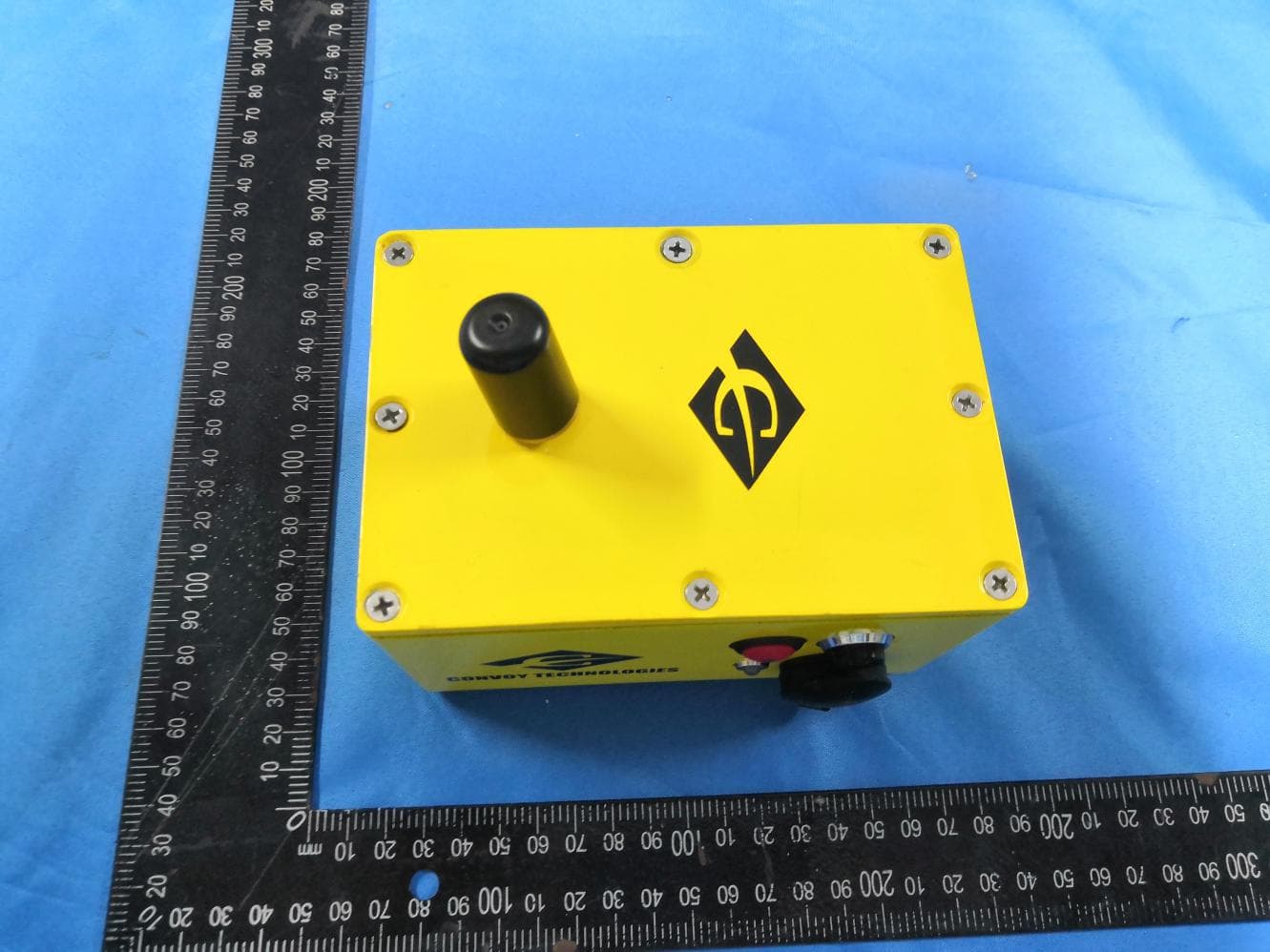
2AA4QC7010
Dec 17, 2020Wireless Video Camera
Equipment Class
DXX - Part 15 Low Power Communication Device Transmitter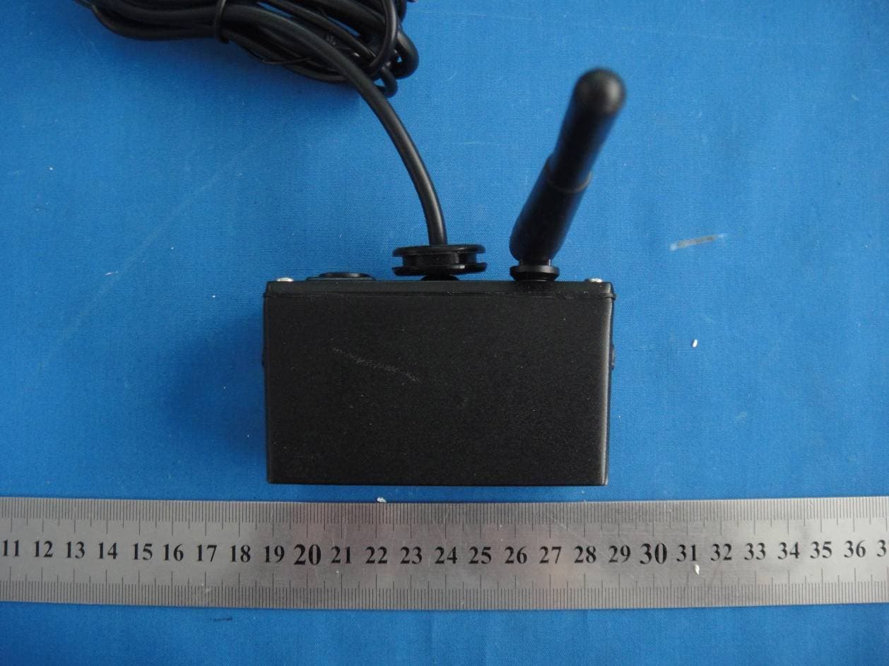
2AA4QC1200
Jun 09, 2014Rear View Wireless Camera
Equipment Class
DXX - Part 15 Low Power Communication Device Transmitter