FCCID.CO- FCC ID Database
HomeCompaniesEquipment ClassesSearch

© 2026 FCC ID Database. All rights reserved.

AboutContactData sourced from FCC public records
  1. Home/
  2. DASAN Network Solutions, Inc./
  3. 2AAAQH640W

2AAAQH640WG-PON ONT

DASAN Network Solutions, Inc.
G-PON ONT - FCC ID 2AAAQH640W - DASAN Network Solutions, Inc.
Click to zoom

Application Details

Equipment Class
DTS - Digital Transmission System
Date of Grant
Nov 20, 2013
Application Purpose
Original Equipment
Date of Application
Nov 20, 2013
Equipment Note
G-PON ONT
Frequency Range
2412.00000000 - 2462.00000000
Company
DASAN Network Solutions, Inc.
Country
South Korea

Documents & Files

Select a file to view

Users Manual

↗

Cover Letter(s)

↗
↗
↗

External Photos

↗

ID Label/Location Info

↗

Internal Photos

↗

RF Exposure Info

↗

Test Report

↗
↗

Test Setup Photos

↗

Document Text

Text extracted from the exhibit documents filed with the FCC. Open a document above to read the original.

Users Manual

H640W Power Adapter RJ45 UTP Cable QIG (Quick Guide) 2.3 Rear View ② Connect the Ethernet cable from LAN port to PC. ③ Connect a power adapter from power port to a live AC outlet. ④ Turn on the unit by pushing the power switch. ⑤ Push WLAN button to enable WLAN. ⑥ Adjust antenna direction for better wireless communication. You can make antennas oblique outside or inside the body by tilting and rotating them. ① Loosen a fixing screw, and pull the upper cover out to remove it. Connect an SC/APC connector cable to GPON port, and then arrange optical line through splice tray and line guide, not to give damage to GPON connection due to any possible pull. And then close the cover, and fix it by tightening the screw. 3. Installation GPON Optical Network Terminal (ONT) with Wi-Fi H640W QIG (Quick Guide) It emDescription ① OPTIC LINEConnect the network. ② LAN1~4Connect PC or LAN. ③ USBConnect an external USB device for management. ④ ON/OFFTurn on/off the unit. ⑤ Power PortConnect power adapter. ⑥ RESETReboot the unit. ⑦ WLANEnable wireless function. ⑧ AntennaTransmit and receive wireless packets. V1 2.2 Specification It emSpecification System Memory128MB DDR3 Flash Memory128MB Nand Flash 1 GPON port (SC/APC) Uplink Interface Service Interface4 10/100/1000Base-T ports (RJ45) USB Interface1 USB host Wireless 2 detachable antennas IEEE 802.11b/g/n compliant Bandwidth: 2.4GHz Two Transmit and Two Receive path (2T2R) LEDPWR, PON, LOS, USB, WLAN, LAN1~4 AC/DC Adapter Operating Temp. 12VDC/1.5A Power ConsumptionMax. 14W 0 ~ 40°C Relative Humidity5 ~ 95% (non-condensing) Dimensions (W x D x H) 160 × 147 × 40 mm ButtonOn/Off power switch, WLAN, RESET LabelLightSt atusDescription PWRGreen On OffThe system is turned off. The system is turned on. Received optical power normal Received optical power is less than optical receiver sensitivity. PONGreen OnRegister OK. The SFF port link is up. BlinkRegister is starting. OffNot register. The SFF port link is down. LOSRed Off Blink OffLink is down. LAN 1~4 Green OnThe 1G port link is up. Blink on the service port. Orange OnThe 100M port link is up. Blink on the service port. The 1G transmit or receive activity is present The 100M transmit or receive activity is present USBGreen OnUSB is connected, and working normally. BlinkData is being transmitted. Off USB is not connected, or power is not fed. WLANGreen OnWireless function enabled BlinkWireless transmit or receive activity is present. Off Wireless function disabled 2.4 Front View (LEDs) GPON Port 4. Initial Web Access You can access H640W through a web browser by using the “initial LAN IP” at first. The detail procedure is as follows: ① Connect LAN1 port of H640W to your PC using Ethernet cable. ② Configure IP assignment of your PC to DHCP (dynamic assignment). How to configure dynamic IP on your PC is as follows: For Windows XP: Start > Setting > Network Connections > Local Area Connection double click > Internet Protocol (TCP/IP) double click > Obtain an IP address automatically and Obtain DNS server address automatically selection > OK For Windows 7: Start > Control Panel > View network status and tasks under Network and Internet (View by: Category) > Change adapter settings on the left menu > Local Area Connection right-click > Properties > Internet Protocol Version 4 (TCP/IPv4) double click > > Obtain an IP address automatically and Obtain DNS server address automatically selection > OK The PC will be allocated 192.168.1.1~254 automatically through H640W. ③ Open a web browser, and enter http://192.168.1.100:8080 in a URL field. ④ Type “user/user” in user name/password field, and log into the system. Initial page is displayed. The default SSID and its key are as follows: SSID: DASAN_GONT / Key: 1234567890a To change the password, on the web above, Basic Settings > Wireless LAN > SSID Setting > Click Modify > Change password > Click Apply. 3 4 5 6 7 8 Fixing Screw Splice Tray Line Guide 3 4 5 6 2 1. Caution - This unit is indoor use and all the communication wirings are limited to inside of the building. - Never look directly at the fiber TX port and fiber cable ends when they are powered on. - DO NOT use near water. - DO NOT place near high temperature source. - DO NOT disassemble the unit. - DO NOT operate the unit in a location where the maximum ambient temperature exceeds 104°F. - Open optical connections must use a protective cap under all circumstances to protect against physical damage and dirt. - Avoid impact stresses when handling connectors. Physical damage to the faces of optical connections impairs transmission quality (higher attenuation). - Avoid a bend radius in excess of 1.18 in for fiber optic links. - Check the available voltage supply. - Only connect approved accessories. - It may only be repaired by authorized service personnel. FCC Certification Requirements ● Caution Any changed or modifications not expressly approved by the party responsible for compliance could void the user`s authority to operate this equipment. ● FCC RF exposure requirements The antenna used with this module must be installed to provide a separation distance of at least 20cm from all persons, and must not transmit simultaneously with any other antenna or transmitter except in accordance with FCC multi-transmitter product procedures. ● User Information This device complies with Part 15 of the FCC`s Rule. Operation is subject to the following to conditions; 1. This device may not cause harmful interference, and 2. This device must accept any interference received, including interference that may cause undesirable operation. This equipment has been tested and found to comply with the limits for a Class B digital device, pursuant to part 15 of the FCC Rules. These limits are designed to provide reasonable protection against harmful interference in a residential installation. This equipment generates, uses and can radiate radio frequency energy and, if not installed and used in accordance with the instructions, may c…

Text truncated - open the document above for the full version.

Cover Letter(s)

DASAN Networks Inc. DASAN Tower, 49, Daewangpangyo-ro 644 Beon-gil, Bundang-gu, Seongnam-si, Gyeonggi-do, Korea Date: November 05, 2013 Compliance Certification Services Certification Division 47173 Benicia Street Fremont, CA 94538, USA To whom it may concern: I, the undersigned, hereby authorize Ms. Claire Hoque/Application Examiner of Compliance Engineering Services, Inc., d.b.a. Compliance Certification Services and hereafter referred to as CCS, to act on our behalf in all manners relating to application for equipment authorization, including signing of all documents relating to these matters. Any and all acts carried out by Ms. Claire Hoque of CCS on our behalf shall have the same effect as acts of our own. In authorizing CCS as our agent, we still recognize that we are responsible to: a) comply with the relevant provisions of the certification program; b) make all necessary arrangements for the conduct of the evaluation, including provision for examining documentation and access to all areas, records (including internal audit reports) and personnel for the purposes of evaluation (e.g. testing, inspection, assessment, surveillance, reassessment) and resolution of complaints; c) make claims regarding certification only in respect of the scope for which certification has been granted; d) do not use our product certification in such a manner as to bring the Certification Division into disrepute and not make any statement regarding our product certification which the Certification Division may consider misleading or unauthorized; e) upon suspension or cancellation of certification, discontinue use of all advertising matter that contains any reference thereto and return any certification documents as required by the Certification Division; f) use certification only to indicate the products are certified as being in conformity with specified standards;

Cover Letter(s)

DASAN Networks Inc. DASAN Tower, 49, Daewangpangyo-ro 644 Beon-gil, Bundang-gu, Seongnam-si, Gyeonggi-do, Korea Date: November 05, 2013 Compliance Certification Services Certification Division 47173 Benicia Street Fremont, CA 94538, USA LETTER OF AUTHORIZATION We, the undersigned, hereby authorize Harvey Sung of Digital EMC Co., Ltd. to act on our behalf in all manners relating to application for equipment authorization for FCC ID: 2AAAQH640W including signing of all documents relating to these matters. Any and all acts carried out by Harvey Sung of Digital EMC Co., Ltd. on our behalf shall have the same affect as acts of our own. This authorization is valid until further written notice from DASAN Networks Inc. “I, the undersigned, hereby certify that we are not subject to a denial of federal benefits, that includes FCC benefits, pursuant to Section 5301 of the Anti-Drug Abuse Act of 1988, 21 U.S.C. 853(a).” Sincerely, YangSik Ryu Manager

Cover Letter(s)

DASAN Networks Inc. DASAN Tower, 49, Daewangpangyo-ro 644 Beon-gil, Bundang-gu, Seongnam-si, Gyeonggi-do, Korea Date: November 05, 2013 Compliance Certification Services Certification Division 47173 Benicia Street Fremont, CA 94538, USA RE: Request of Confidentiality for FCCID: 2AAAQH640W To Whom It may Concern: Pursuant to Sections 0.457 and 0.459 of the Commission`s Rules(CFR 47), and Section 552 (b) (4) of the Freedom of Information Act, DASAN Networks Inc. hereby requests confidentiality and treatment of certain information accompanying this application. The materials contain trade secrets and proprietary information not customarily released to the public. The public disclosure of these matters might be harmful to the Applicant and provide unjustified benefits to its competitors. We are also hereby request Short-Term Confidentiality for 180 days after the grant as outlined in Public Notice DA 04-1705. This provision will give DASAN Networks Inc. temporary confidentiality of commercially sensitive information prior to product release. The requested permanent and Short-Term Confidential exhibits are listed as follows: PERMANENT & SHORT-TERM CONFIDENTIAL LIST Exhibit Description PERMANENT 1 Block Diagram 2 Operational Description 3 Schematics 4 Part Lists SHORT-TERM 5 External Photos 6 Internal Photos 7 Test-Setup Photos 8 Users Manual The Applicant understands that pursuant to Rule 0.457, disclosure of this application and all accompanying documentations, where applicable, will not be public before the date of the Grant for this application. Sincerely, YangSik Ryu Manager

External Photos

FCCID: 2AAAQH640W Copyright Ⓒ 2013, Digital EMC Co., Ltd. View 1 FCCID: 2AAAQH640W Copyright Ⓒ 2013, Digital EMC Co., Ltd. View 2 FCCID: 2AAAQH640W Copyright Ⓒ 2013, Digital EMC Co., Ltd. View 3

ID Label/Location Info

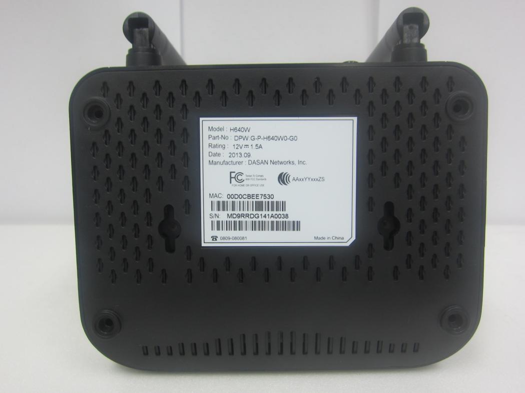
FCC ID: 2AAAQH640W Copyright Ⓒ 2013, Digital EMC Co., Ltd. FCC ID SAMPLE LABEL & LOCATION LABELLING REQUIREMENTS PER §2.925 The Label shown shall be permanently affixed at a conspicuous location on the device and be readily visible to the user at the time of purchase Label locate rear side - The FCC label shown is representative of the label that will appear on the radio when in production. Other information may also be included on this label.

Internal Photos

FCCID: 2AAAQH640W Copyright Ⓒ 2013, Digital EMC Co., Ltd. Page 1 / 3 View 1 FCCID: 2AAAQH640W Copyright Ⓒ 2013, Digital EMC Co., Ltd. Page 2 / 3 View 2 FCCID: 2AAAQH640W Copyright Ⓒ 2013, Digital EMC Co., Ltd. Page 3 / 3 View 3

RF Exposure Info

-~ - - + &dBm ) - - The MPE calculation for this exposure is shown below. ▪=+- =+ == - ▪S=- = = MPE Calculations(WLAN: 802.11b) dBm Min. Frequency range : 2412 MHz2462 MHz EIRP = Equivalent Isotropic Radiated Power(mW) 329.61 mW Maximum output power for the calculatio 20.50 P = Power input to the antenna(dBm) 25.18 dBm dBm The EUT will only be used with a separation of 20 centimeters or greater between the antenna and the body of the 2AAAQH640WDASAN Networks Inc. Target Power & Tolerance : 20.00 dBm0.5 dB ( Max. 20.5 - FCCID: R = Distance to the center of the radiation of the antenna(20cm) Conclusion : The exposure condition of this device is compliant with FCC rules. The maximum permissible exposure(MPE) of the general population/Uncontrolled for this device is 1.0 mW/cm 2 . S = Maximum power dencity(mW/cm 2 ) 0.065574 mW/cm 2 / ( 4 X 20 2 X π ) 329.610 G = Power gain of the antenna(dBi) Power density at the specific separation EIRP / ( 4 R 2 π ) Note EIRPPGNote 20.50 dBm4.68 dBi Measured RF output power :20.15 dBm Maximum antenna peak gain : 4.68 dBi -~ - - + &dBm ) - - The MPE calculation for this exposure is shown below. ▪=+- =+ == - ▪S=- = = The maximum permissible exposure(MPE) of the general population/Uncontrolled for this device is 1.0 mW/cm 2 . MPE Calculations(WLAN: 802.11g) 0.130837 mW/cm 2 EIRP = Equivalent Isotropic Radiated Power(mW) R = Distance to the center of the radiation of the antenna(20cm) Conclusion : The exposure condition of this device is compliant with FCC rules. Power density at the specific separation EIRP / ( 4 R 2 π ) Note 657.658 / ( 4 X 20 2 X π )S = Maximum power dencity(mW/cm 2 ) P = Power input to the antenna(dBm) 28.18 dBm657.658 mWG = Power gain of the antenna(dBi) The EUT will only be used with a separation of 20 centimeters or greater between the antenna and the body of the EIRPPGNote 23.50 dBm4.68 dBi Maximum antenna peak gain : 4.68 dBi Maximum output power for the calculatio 23.50 dBm 0.5 dB ( Max. 23.5 dBm Min. Measured RF output power :23.32 dBm Target Power & Tolerance : 23.00 dBm - FCCID: 2AAAQH640WDASAN Networks Inc. Frequency range : 2412 MHz2462 MHz -~ - - + &dBm ) - - The MPE calculation for this exposure is shown below. ▪=+- =+ == - ▪S=- = = The maximum permissible exposure(MPE) of the general population/Uncontrolled for this device is 1.0 mW/cm 2 . 0.164715 mW/cm 2 EIRP = Equivalent Isotropic Radiated Power(mW) R = Distance to the center of the radiation of the antenna(20cm) Conclusion : The exposure condition of this device is compliant with FCC rules. Power density at the specific separation EIRP / ( 4 R 2 π ) Note 827.943 / ( 4 X 20 2 X π )S = Maximum power dencity(mW/cm 2 ) P = Power input to the antenna(dBm) 29.18 dBm827.943 mWG = Power gain of the antenna(dBi) The EUT will only be used with a separation of 20 centimeters or greater between the antenna and the body of the EIRPPGNote 24.50 dBm4.68 dBi Maximum antenna peak gain : 4.68 dBi Maximum output power for the calculatio 24.50 dBm 1.5 dB ( Max. 24.5 dBm Min. Measured RF output power :24.43 dBm Target Power & Tolerance : 23.00 dBm - FCCID: 2AAAQH640WDASAN Networks Inc. MPE Calculations(WLAN: 802.11n HT20) Frequency range : 2412 MHz2462 MHz -~ - - + &dBm ) - - The MPE calculation for this exposure is shown below. ▪=+- =+ == - ▪S=- = = The maximum permissible exposure(MPE) of the general population/Uncontrolled for this device is 1.0 mW/cm 2 . 0.103928 mW/cm 2 EIRP = Equivalent Isotropic Radiated Power(mW) R = Distance to the center of the radiation of the antenna(20cm) Conclusion : The exposure condition of this device is compliant with FCC rules. Power density at the specific separation EIRP / ( 4 R 2 π ) Note 522.397 / ( 4 X 20 2 X π )S = Maximum power dencity(mW/cm 2 ) P = Power input to the antenna(dBm) 27.18 dBm522.397 mWG = Power gain of the antenna(dBi) The EUT will only be used with a separation of 20 centimeters or greater between the antenna and the body of the EIRPPGNote 22.50 dBm4.68 dBi Maximum antenna peak gain : 4.68 dBi Maximum output power for the calculatio 22.50 dBm 1.5 dB ( Max. 22.5 dBm Min. Measured RF output power :22.43 dBm Target Power & Tolerance : 21.00 dBm - FCCID: 2AAAQH640WDASAN Networks Inc. MPE Calculations(WLAN: 802.11n HT40) Frequency range : 2422 MHz2452 MHz

Test Report

FCCID: 2AAAQH640W DEMC1309-02988 Report No.: DRTFCC1311-1078 TRF-RF-213(02)130923 Page2 / 86 Copyright ○ C 2013, Digital EMC Co., Ltd. Test Report Version Test Report No. Date Description DRTFCC1311-1078 Nov. 11, 2013 Initial issue FCCID: 2AAAQH640W DEMC1309-02988 Report No.: DRTFCC1311-1078 TRF-RF-213(02)130923 Page3 / 86 Copyright ○ C 2013, Digital EMC Co., Ltd. Table of Contents 1. GENERAL INFORMATION ........................................................ 4 2. EUT DESCRIPTION ................................................................... 4 3. SUMMARY OF TESTS ............................................................... 5 4. TEST METHODOLOGY ............................................................. 6 4.1 EUT CONFIGURATION ..................................................................................... 6 4.2 EUT EXERCISE ................................................................................................. 6 4.3 GENERAL TEST PROCEDURES ...................................................................... 6 4.4 DESCRIPTION OF TEST MODES ..................................................................... 6 5. INSTRUMENT CALIBRATION ................................................... 7 6. FACILITIES AND ACCREDITATIONS ........................................ 7 6.1 FACILITIES ........................................................................................................ 7 6.2 EQUIPMENT ...................................................................................................... 7 7. ANTENNA REQUIREMENTS ..................................................... 7 8. TEST RESULT ........................................................................... 8 8.1 6dB Bandwidth ................................................................................................. 8 8.2 Maximum Peak Conducted Output Power .................................................... 21 8.3 Maximum Power Spectral Density ................................................................. 25 8.4 Out of Band Emissions at the Band Edge / Conducted Spurious Emissions ......... 38 8.5 Radiated Spurious Emissions ....................................................................... 75 8.6 Power-line Conducted Emissions ................................................................. 81 8.7 Occupied Bandwidth ...................................................................................... 84 9. LIST OF TEST EQUIPMENT .................................................... 85 APPENDIX I ................................................................................. 86 FCCID: 2AAAQH640W DEMC1309-02988 Report No.: DRTFCC1311-1078 TRF-RF-213(02)130923 Page4 / 86 Copyright ○ C 2013, Digital EMC Co., Ltd. 1. GENERAL INFORMATION Applicant : DASAN Networks Inc. Address : DASAN Tower, 49, Daewangpangyo-ro 644Beon-gil, Bundang-gu, Seongnam-si, Gyeonggi-do, 463-400 KOREA FCC ID : 2AAAQH640W EUT : G-PON ONT Model : H640W Additional Model(s) : N/A Data of Test : 2013-10-02 ~ 2013-10-24 Contact person : YangSik Ryu 2. EUT DESCRIPTION Product G-PON ONT Model Name H640W Power Supply DC 12 V Frequency Range 2.4GHz Band ▪ 802.11b/g/n(20MHz): 2412 MHz ~ 2462 MHz ▪ 802.11n(40MHz): 2422 MHz ~ 2452 MHz Max. RF Output Power 2.4GHz Band ▪ 802.11b: 20.15 dBm ▪ 802.11g: 23.32 dBm ▪ 802.11n (HT20): 24.43 dBm ▪ 802.11n (HT40): 22.43 dBm Modulation Type 802.11b: DSSS/CCK 802.11g/n: OFDM Antenna Specification Antenna type: Dipole antenna Antenna gain: Chain 1 : 4.68 dBi & Chain 2 : 4.68 dBi Directional Antenna gain for MIMO with uncorrelated signals : 4.68 dBi Antenna configuration ▪ 802.11b/g: Single Transmitting (chain 1 only) ▪ 802.11n(MCS0 ~ 7) : Single Transmitting (chain 1 or 2) ▪ 802.11n(MCS8 ~ 15): Multiple Transmitting (chain 1 and 2) FCCID: 2AAAQH640W DEMC1309-02988 Report No.: DRTFCC1311-1078 TRF-RF-213(02)130923 Page5 / 86 Copyright ○ C 2013, Digital EMC Co., Ltd. 3. SUMMARY OF TESTS FCC Part Section(s) RSS Section(s) Parameter Limit Test Condition Status Note 1 I. Transmitter Mode (TX) 15.247(a) RSS-210 [A8.2] 6 dB Bandwidth > 500 kHz Conducted C 15.247(b) RSS-210 [A8.4] Transmitter Output Power < 1Watt C 15.247(d) RSS-210 [A8.5] Out of Band Emissions / Band Edge 20dBc in any 100kHz BW C 15.247(e) RSS-210 [A8.2] Transmitter Power Spectral Density < 8dBm / 3kHz C - RSS Gen [4.6.1] Occupied Bandwidth (99%) RSS-Gen(4.6.1) NA 15.205 15.209 RSS-210 [A8.5] General Field Strength Limits (Restricted Bands and Radiated Emission Limits) < FCC 15.209 limits Radiated C Note2 15.207 RSS-Gen [7.2.4] AC Conducted Emissions < FCC 15.207 limits AC Line Conducted C 15.203 - Antenna Requirements FCC 15.203 - C Note 1: C=Comply NC=Not Comply NT=Not Tested NA=Not Applicable Note 2: This test item was performed in each axis and the worst case data was reported. FCCID: 2AAAQH640W DEMC1309-02988 Report No.: DRTFCC1311-1078 TRF-RF-213(02)130923 Page6 / 86 Copyright ○ C 2013, Digital EMC Co., Ltd. 4. TEST METHODOLOGY Generally the tests were performed according to the KDB558074 v03r1. And ANSI C63.10-2009 was used to reference appropriate EUT setup and maximizing procedures of radiated spurious emission and AC line conducted emission testing 4.1 EUT CONFIGURATION The EUT configuration for testing is installed on RF field strength measurement to meet the Commissions requirement and operating in a manner that intends to maximize its emission characteristics in a continuous normal application. 4.2 EUT EXERCISE The EUT was operated in the engineering mode to fix the Tx frequency that was for the purpose of the measurements. According to its specifications, the EUT must comply with the requirements of the Section 15.207, 15.209 and 15.247 under the FCC Rules Part 15 Subpart C. 4.3 GENERAL TEST PROCEDURES Conducted Emissions The power-line conducted emission test procedure is not described on the KDB 558074 v03r1. So this test was fulfilled with the requirements in Section 6.2 of ANSI C63.10. The EUT is placed on the…

Text truncated - open the document above for the full version.

Test Report

FCCID: 2AAAQH640W DEMC1309-02988 Report No.: DRTFCC1311-1078 TRF-RF-213(02)130923 Page38 / 86 Copyright ○ C 2013, Digital EMC Co., Ltd. 8.4 Out of Band Emissions at the Band Edge / Conducted Spurious Emissions Test requirements and limit, §15.247(d) §15.247(d) specifies that in any 100 kHz bandwidth outside of the authorized frequency band, the power shall be attenuated according to the following conditions: If the peak output power procedure is used to measure the fundamental emission power to demonstrate compliance to 15.247(b)(3) requirements, then the peak conducted output power measured within any 100 kHz outside the authorized frequency band shall be attenuated by at least 20 dB relative to the maximum measured in-band peak PSD level. If the average output power procedure is used to measure the fundamental emission power to demonstrate compliance to 15.247(b)(3) requirements, then the power in any 100 kHz outside of the authorized frequency band shall be attenuated by at least 30 dB relative to the maximum measured in band average PSD level. In either case, attenuation to levels below the general emission limits specified in §15.209(a) is not required. ▣TEST CONFIGURATION Refer to the APPENDIX I. ▣TEST PROCEDURE The transmitter output is connected to a spectrum analyzer. - Measurement Procedure 1 – Reference Level 1. Set instrument center frequency to DTS channel center frequency. 2. Set the span to ≥ 1.5 times the DTS bandwidth. 3. Set the RBW = 100 kHz. 4. Set the VBW ≥ 3 x RBW. 5. Detector = peak. 6. Sweep time = auto couple. 7. Trace mode = max hold. 8. Allow trace to fully stabilize. 9. Use the peak marker function to determine the maximum PSD level - Measurement Procedure 2 - Unwanted Emissions 1. Set the center frequency and span to encompass frequency range to be measured. 2. Set the RBW = 100 kHz.( Actual 1 MHz , See below note) 3. Set the VBW ≥ 3 x RBW.(Actual 3 MHz, See below note) 4. Detector = peak. 5. Ensure that the number of measurement points ≥ span/RBW 6. Sweep time = auto couple. 7. Trace mode = max hold. 8.Allow the trace to stabilize (this may take some time, depending on the extent of the span). 9. Use the peak marker function to determine the maximum amplitude level. Note : The conducted spurious emission was tested each ranges were set as below. Frequency range : 30MHz~10GHz, 10GHz~25GHz RBW= 1MHz, VBW= 3MHz, SWEEP TIME = AUTO, DETECTOR = PEAK, TRACE = MAX HOLD, BINS : 40001 If the emission level with above setting was close to the limit (ie, less than 3 dB margin) then zoom scan is required using RBW = 100 KHz, VBW = 300KHz, SAPN = 100 MHz and BINS = 2001 to get accurate emission level within 100 KHz BW. Also the path loss for conducted measurement setup was used as described on the Appendix I of this test report. FCCID: 2AAAQH640W DEMC1309-02988 Report No.: DRTFCC1311-1078 TRF-RF-213(02)130923 Page39 / 86 Copyright ○ C 2013, Digital EMC Co., Ltd. ▣RESULT PLOTS Test Mode: Chain 1 & 802.11b & 1 Mbps & 2412MHz Reference Low Band-edge FCCID: 2AAAQH640W DEMC1309-02988 Report No.: DRTFCC1311-1078 TRF-RF-213(02)130923 Page40 / 86 Copyright ○ C 2013, Digital EMC Co., Ltd. Conducted Spurious Emissions FCCID: 2AAAQH640W DEMC1309-02988 Report No.: DRTFCC1311-1078 TRF-RF-213(02)130923 Page41 / 86 Copyright ○ C 2013, Digital EMC Co., Ltd. Test Mode: Chain 1 & 802.11b & 1 Mbps & 2437MHz Reference Conducted Spurious Emissions FCCID: 2AAAQH640W DEMC1309-02988 Report No.: DRTFCC1311-1078 TRF-RF-213(02)130923 Page42 / 86 Copyright ○ C 2013, Digital EMC Co., Ltd. Conducted Spurious Emissions FCCID: 2AAAQH640W DEMC1309-02988 Report No.: DRTFCC1311-1078 TRF-RF-213(02)130923 Page43 / 86 Copyright ○ C 2013, Digital EMC Co., Ltd. Test Mode: Chain 1 & 802.11b & 1 Mbps & 2462MHz Reference High Band-edge FCCID: 2AAAQH640W DEMC1309-02988 Report No.: DRTFCC1311-1078 TRF-RF-213(02)130923 Page44 / 86 Copyright ○ C 2013, Digital EMC Co., Ltd. Conducted Spurious Emissions FCCID: 2AAAQH640W DEMC1309-02988 Report No.: DRTFCC1311-1078 TRF-RF-213(02)130923 Page45 / 86 Copyright ○ C 2013, Digital EMC Co., Ltd. Test Mode: Chain 1 & 802.11g & 6 Mbps & 2412MHz Reference Low Band-edge FCCID: 2AAAQH640W DEMC1309-02988 Report No.: DRTFCC1311-1078 TRF-RF-213(02)130923 Page46 / 86 Copyright ○ C 2013, Digital EMC Co., Ltd. Conducted Spurious Emissions FCCID: 2AAAQH640W DEMC1309-02988 Report No.: DRTFCC1311-1078 TRF-RF-213(02)130923 Page47 / 86 Copyright ○ C 2013, Digital EMC Co., Ltd. Test Mode: Chain 1 & 802.11g & 6 Mbps & 2437MHz Reference Conducted Spurious Emissions FCCID: 2AAAQH640W DEMC1309-02988 Report No.: DRTFCC1311-1078 TRF-RF-213(02)130923 Page48 / 86 Copyright ○ C 2013, Digital EMC Co., Ltd. Conducted Spurious Emissions FCCID: 2AAAQH640W DEMC1309-02988 Report No.: DRTFCC1311-1078 TRF-RF-213(02)130923 Page49 / 86 Copyright ○ C 2013, Digital EMC Co., Ltd. Test Mode: Chain 1 & 802.11g & 6 Mbps & 2462MHz Reference High Band-edge FCCID: 2AAAQH640W DEMC1309-02988 Report No.: DRTFCC1311-1078 TRF-RF-213(02)130923 Page50 / 86 Copyright ○ C 2013, Digital EMC Co., Ltd. Conducted Spurious Emissions FCCID: 2AAAQH640W DEMC1309-02988 Report No.: DRTFCC1311-1078 TRF-RF-213(02)130923 Page51 / 86 Copyright ○ C 2013, Digital EMC Co., Ltd. Test Mode: Chain 1 & 802.11n(HT20) & MCS8 & 2412MHz Reference Low Band-edge FCCID: 2AAAQH640W DEMC1309-02988 Report No.: DRTFCC1311-1078 TRF-RF-213(02)130923 Page52 / 86 Copyright ○ C 2013, Digital EMC Co., Ltd. Conducted Spurious Emissions FCCID: 2AAAQH640W DEMC1309-02988 Report No.: DRTFCC1311-1078 TRF-RF-213(02)130923 Page53 / 86 Copyright ○ C 2013, Digital EMC Co., Ltd. Test Mode: Chain 1 & 802.11n(HT20) & MCS8 & 2437MHz Reference Conducted Spurious Emissions FCCID: 2AAAQH640W DEMC1309-02988 Report No.: DRTFCC1311-1078 TRF-RF-213(02)130923 Page54 / 86 Copyright ○ C 2013, Digital EMC Co., Ltd. Conducted Spurious Emissions FCCID: 2AAAQH640W DEMC1309-02988 Report No.: DRTFCC1311-1078 TRF-RF-213(02)130923 Page55 / 86 Copyright ○ C 2013, Digital EMC Co., Ltd. Test Mode: Chain…

Text truncated - open the document above for the full version.

Test Setup Photos

FCC ID: 2AAAQH640W Copyright Ⓒ 2013, Digital EMC Co., Ltd. Test Setup photographs (DTS) EUT Position: X-axis FCC ID: 2AAAQH640W Copyright Ⓒ 2013, Digital EMC Co., Ltd. Test Setup photographs (DTS) EUT Position: Y-axis FCC ID: 2AAAQH640W Copyright Ⓒ 2013, Digital EMC Co., Ltd. Test Setup photographs (DTS) EUT Position: Z-axis FCC ID: 2AAAQH640W Copyright Ⓒ 2013, Digital EMC Co., Ltd. Test Setup photographs (DTS)

Contact Information

Applicant

YangSik Ryu
[email protected]+82-70-7010-1514Fax: +82-31-622-6511

Test Firm

Dt&C Co., Ltd.Lee Sang-Wook
[email protected]82-31-321-2664Fax: 82-31-321-1664

Technical Specifications

#Rule PartsFrequency RangePower Output
115C2.41 GHz - 2.46 GHz277.00 mW
Confidentiality
Long Term
Grant Notes
Output power listed is conducted. This device supports both 20 MHz and 40MHz bandwidths. Only antenna (s) documented in this filings may be used with this transmitter. The transmitter must be installed to provide a separation distance of at least 20 cm from all persons and must not be collocated or operating in conjunction with any other transmitter.

Other Applications from DASAN Network Solutions, Inc.
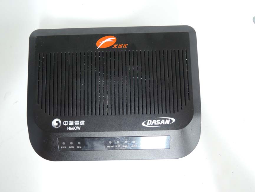
G-PON ONT - FCC ID 2AAAQH660W - DASAN Network Solutions, Inc.
2AAAQH660W

G-PON ONT

Oct 01, 2014

Equipment Class

DTS - Digital Transmission System