2AABGQ3034-3MBT Dual mode Module
EnzyTek Technoloy Inc.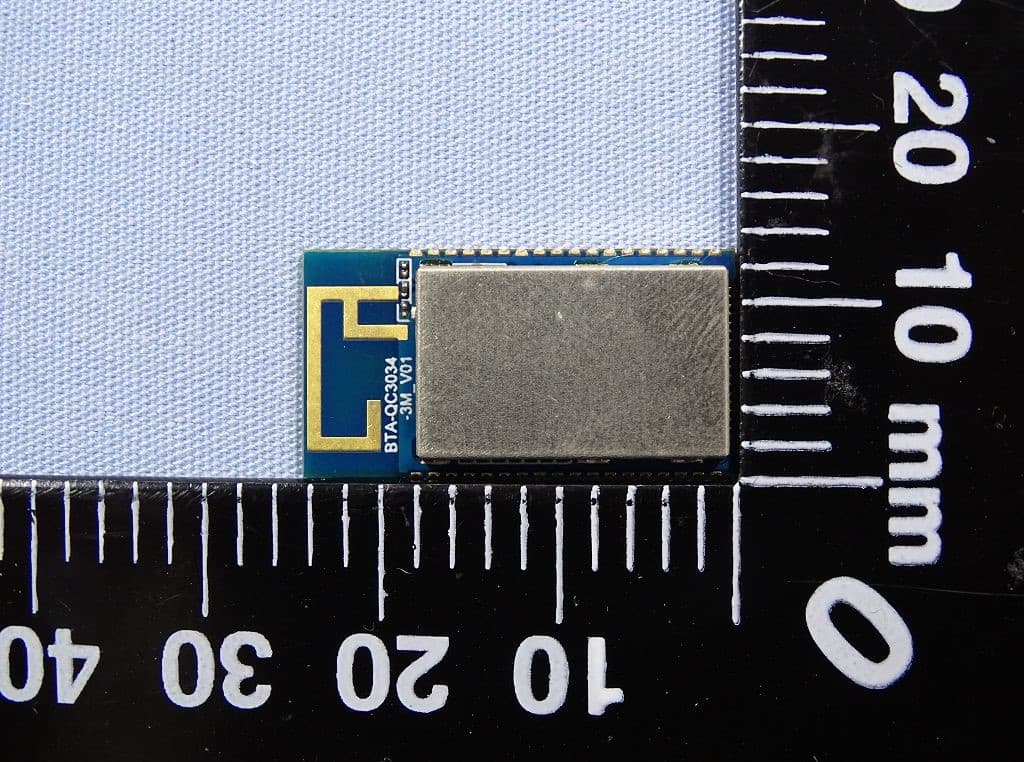
Click to zoom
Application Details
- Equipment Class
- DTS - Digital Transmission System
- Date of Grant
- Sep 21, 2020
- Application Purpose
- Original Equipment
- Date of Application
- Sep 10, 2020
- Equipment Note
- BT Dual mode Module
- Frequency Range
- 2402.00000000 - 2480.00000000
- Company
- EnzyTek Technoloy Inc.
- Country
- Taiwan
Documents & Files
Document Text
Text extracted from the exhibit documents filed with the FCC. Open a document above to read the original.
Users Manual
EnzyTek Technology, Inc. 7F, No. 35, Hsueh Fu Rd., Hsinchu 300, Taiwan , R.O.C. TEL:886-3-573-6708 FAX: 886-3-573-8749 1/25 BTA-QC3034-3M Preliminary Datasheet (Version 01) Issued date: September 9, 2020 This device is intended only for OEM integrators under the following conditions: The use of the printed antenna with gain=-0.46dBi(2.4GHz) IMPORTANT NOTE: In the event that these conditions can’t be met (for example certain laptop configurations or co-location with another transmitter), then the FCC authorization is no longer considered valid and FCC ID can’t be used on the final product. In these circumstances, the OEM integrator will be responsible for re-evaluating the end product(including the transmitter) and obtain a separate FCC authorization. End Product Labeling The final end product must be labeled in a visible area with the following: “Contains FCC ID: 2AABGQ3034-3M”.The grantee’s FCC ID can be used only when all FCC compliance requirements are met. EnzyTek Technology, Inc. 7F, No. 35, Hsueh Fu Rd., Hsinchu 300, Taiwan , R.O.C. TEL:886-3-573-6708 FAX: 886-3-573-8749 2/25 EnzyTek Bluetooth ® Class II Module – BTA-QC3034-3M Product Description BTA-QC3034-3M is a highly integrated small form factor (24.5x13 mm 2 ) Bluetooth class II module which adopts Qualcomm QCC3034 as core chip for Bluetooth operation. QCC3034 VFBGA is a system on-chip (SoC) with on-chip Bluetooth, audio and programmable application processor. It includes high-performance, analog, and digital audio codecs, Class-AB and Class-D headphone drivers, advanced power management, Li-ion battery charger, light-emitting diode (LED) drivers, and flexible interfaces including inter- integrated circuit sound (I²S), inter-integrated circuit interface (I²C), universal asynchronous receiver transmitter (UART), and programmable input/output (PIO). EnzyTek Technology, Inc. 7F, No. 35, Hsueh Fu Rd., Hsinchu 300, Taiwan , R.O.C. TEL:886-3-573-6708 FAX: 886-3-573-8749 3/25 FEATURES Highly integrated BT 5.0 module QCC3034 (embedded Balun + Filter + Crystal + Flash + PCB Antenna) 120 MHz Qualcomm® Kalimba™ audio DSPs 32 MHz Developer Processor for applications Firmware Processor for system Flexible QSPI flash programmable platform Advanced audio algorithms High-performance 24‑bit stereo audio interface Digital and analog microphone interfaces Flexible PIO controller and LED pins with PWM support 1 or 2-mic Qualcomm® cVc™ headset noise reduction and echo cancellation technology aptX, aptX HD, aptX Low Latency, SBC, and AAC audio codecs support Serial interfaces: UART, Bit Serializer (I²C/SPI), USB 2.0 Integrated PMU: Dual SMPS for system/digital circuits, Integrated Li-ion battery charger Frequency: 2402 ~ 2480 GHz TX Output Power : 9 dBm/(Max) RX Sensitivity : -90 dBm (typ) Dimension : 24.5 mm x 13 mm x 2.8/3.2 mm (L x W x H) Temperature :-10~+70〬C Applications Wired/wireless stereo headsets/headphones Qualcomm TrueWireless™ stereo earbuds EnzyTek Technology, Inc. 7F, No. 35, Hsueh Fu Rd., Hsinchu 300, Taiwan , R.O.C. TEL:886-3-573-6708 FAX: 886-3-573-8749 4/25 Audio subsystem 32‑bit Kalimba audio digital signal processor (DSP) core with flexible clocking from 2 MHz to 120 MHz to allow optimization and trade-off performance vs. power consumption DSP runs from ROM 80 KB program random access memory (RAM) 256 KB data RAM 5 Mb ROM Application subsystem Dual core application subsystem 32 MHz operation 32‑bit Firmware Processor: □ Reserved for system use □ Runs Bluetooth upper stack, profiles, house-keeping code 32‑bit Developer Processor: □ Runs developer applications Both cores execute code from external flash memory using QSPI clocked at 32 MHz On-chip caches per core allow for optimized performance and power consumption Bluetooth subsystem Qualified to Bluetooth v5.0 specification including 2 Mbps Bluetooth low energy (Production parts) Single ended antenna connection with on-chip balun and Tx/Rx switch Bluetooth, Bluetooth low energy, and mixed topologies supported Class 1/2 support EnzyTek Technology, Inc. 7F, No. 35, Hsueh Fu Rd., Hsinchu 300, Taiwan , R.O.C. TEL:886-3-573-6708 FAX: 886-3-573-8749 5/25 Block Diagram EnzyTek Technology, Inc. 7F, No. 35, Hsueh Fu Rd., Hsinchu 300, Taiwan , R.O.C. TEL:886-3-573-6708 FAX: 886-3-573-8749 6/25 Pinout Diagram & Dimension Unit : mm 0.6mm IO J22 GND IO J18 LED1 IO J45 GND IO J4 PIO18 IO J1 PIO21 IO J3 PIO19 IO J7 PIO15 IO J6 PIO16 IO J5 PIO17 IO J11 VCHG IO J8 GND IO J10 USB_DP IO J9 USB_DN IO J13 CHG_EXT IO J15 VBAT IO J12 VCHG_SENSE IO J16 GND IO J14 SYS_CTRL IO J19 LED2 IO J20 LDE4 IO J21 LED5 IO J25 VDD_PADS_1 IO J23 1V8 IO J24 VDD_PADS_3&7 IO J26 PIO2 IO J27 PIO3 IO J32 PIO8 IO J28 PIO4 IO J31 PIO7 IO J34 GND IO J33 PIO1 IO J35 SPK_RN IO J36 SPK_RP IO J38 SPK_LP IO J37 SPK_LN IO J39 GND IO J42 MIC_RP IO J41 MIC_RN IO J43 MIC_LN IO J44 MIC_LP 13 mm 2.5 mm PCB thickness:0.8mm 1mm IO J30 PIO6 IO J40 MIC_BIAS IO J2 PIO20 IO J46 PIO54 IO J47 PIO53 IO J48 PIO52 IO J49 PIO60 IO J50 PIO61 IO J17 LED0 IO J29 PIO5 1mm2.5mm 1mm 24.5mm 1mm EnzyTek Technology, Inc. 7F, No. 35, Hsueh Fu Rd., Hsinchu 300, Taiwan , R.O.C. TEL:886-3-573-6708 FAX: 886-3-573-8749 7/25 I/O PIN LISTING Pin No. Pin Name Type Description 1 PIO21 Digital: Bidirectional with programmable strength internal pull- up/pull-down Programmable I/O line 21. Alternative function : PCM_DOUT[2] 2 PIO20 Digital: Bidirectional with programmable strength internal pull- up/pull-down Programmable I/O line 20. Alternative function : PCM_DOUT[1] 3 PIO19 Digital: Bidirectional with programmable strength internal pull- up/pull-down Programmable I/O line 19. Alternative function : PCM_DIN[0] 4 PIO18 Digital: Bidirectional with programmable strength internal pull- up/pull-down Programmable I/O line 18. Alternative function : PCM_DOUT[0] 5 PIO17 Digital: Bidirectional with programmable strength internal pull- up/pull-down Programmable I/O line 17. Alternative function : PCM_SYNC 6…
Text truncated - open the document above for the full version.
Cover Letter(s)
(On manuf Declara We Name: Address: City: Country: Declare th a Name Re p Agent Com Address: City: Country is authoriz e Product d e Type desig Trademark Validity/ ex on our be h Date: City: Name: Function: Signature: Notes: (1): Require d (2): For FCC facturer’s co ation of A E 7 H T at: presentative mpany name ed to apply escription: B gnation: B k: E xpiry date half. 2 H P M d for FCC appli it must be the ompany lette Authoriz EnzyTek Te 7F, No. 35,H Hsinchu Taiwan of agent: e: for Certific a BT Dual mod BTA-QC303 Enzytek 2020/09/01 Hsinchu Peter Hsieh Manager ication Grantee Cod e er heading) zation chnoloy Inc Hsueh Fu Rd Gary Wu Wendell 6F/6F-1, New Tai p Taiwan R ation of the f de Module 34-3M e “owner” or th c. d. (1) Industrial C No.188, Ba pei City R.O.C. following pro he authorized a Co., Ltd aoqiao Rd., oduct(s): agent. Xindian Dis RF_ st. _160, Issue 044
Cover Letter(s)
FCC, Request for non-disclosure Date: 19-Oct-10 RF_501, Issue 7 Page 1 of 1 Company Name: EnzyTek Technoloy Inc. Address : 7F, No. 35,Hsueh Fu Rd. City: Hsinchu Country: Taiwan To: Telefication B.V., Dept. FCC TCB Edisonstraat 12A 6902 PK ZEVENAAR The Netherlands Subject: Request for confidentiality FCC ID: 2AABGQ3034-3M Reference number: ###### Dear FCC TCB, 1. Long-Term Confidentiality Pursuant to 47 CFR Section 0.459(a) & (b), we hereby requests non-disclosure and confidential treatment of the following materials submitted in support of FCC certification application: Bill(s) of Material Block Diagrams Operational Description Schematic Diagrams Tune-up Procedure Above materials contain secrets, proprietary and technical information, which would customarily be guarded from competitors under 47 CFR, section 0.457(d)(2). Disclosure or publication or any portion of this company confidential material to other parties could cause substantial competitive harm and provide unjustified benefits for competitors. 2. Short-Term Confidentiality (STC) Pursuant to Public Notice DA 04-1705 of the Commission’s policy, in order to comply with the marketing regulations in 47 CFR §2.803 and the importation rules in 47 CFR §2.1204, a pplicant hereby requests Short-Term Confidential treatment of the following materials (note 1): Internal Photos User’s Manual Test Set-up Photos External Photos Justification: Planned Release Date STC: (notes 2, 3, 4, 5). If no date is given, 45 days from grant date will be used. Date: 2020/09/01 Name and signature of applicant: Peter Hsieh Notes: 1) A document or type of document can only have ONE type of confidentiality! 2) Short-Term confidentiality is in principle for 45 days from date of grant; it can be extended max 3 times (total time 180 days max.)! 3) FCC must be informed when marketing begins earlier. 4) Release takes place automatically thus extension must be requested in time. Telefication does not remind you of this! 5) Request for extension or for release must be received by Telefication at least 7 days before date of actual marketing or before expiration of the STC period
Cover Letter(s)
RF_734_02 04 April 16 Modular Approval Request FCC (KDB 996369 D01 & Part 15.212) FCC ID: 2AABGQ3034-3M Items to be covered by Single modular transmitters. Answer from applicant 1. The modular transmitter must have its own RF shielding. Modular transmitter has their own shielding. 2. The modular transmitter must have buffered modulation/data inputs (if such inputs are provided) to ensure that the module will comply with Part 15 requirements under conditions of excessive data rates or over-modulation. Chipset “QCC3034” have buffered modulation/data inputs ( can refer the schematics)and comply with part 15 requirements under conditions of excessive data rates or over-modulation. 3. The modular transmitter must have its own power supply regulation. Chipset “QCC3034” have its own power supply regulation ( can refer the schematics) 4. The modular transmitter must comply with the antenna requirements of Section 15.203 and 15.204(b)(c). The antenna must either be permanently attached or employ a “unique” antenna coupler (at all connections between the module and the antenna, including the cable). Refer to internal photo. 5. The modular transmitter must be tested in a stand-alone configuration, i.e., the module must not be inside another device during testing. This is intended to demonstrate that the module is capable of complying with Part 15 emission limits regardless of the device into which it is eventually installed. Refer to test setup photo. 6. The modular transmitter must be equipped with either a permanently affixed label or must be capable of electronically displaying its FCC identification number in accordance with 15.212 (a)(1)(vi)(A) / (B). Refer to label. 7. The modular transmitter must comply with any specific rule or operating requirements applicable to the transmitter and the manufacturer must provide adequate instructions along with the module to explain any such requirements. A copy of these instructions must be included in the application for equipment authorization. For example, there are very strict operational and timing requirements that must be met before a transmitter is authorized for operation under Section 15.231. For instance, data transmission is prohibited, except for operation under Section 15.231(e), in which case there are separate field strength level and timing requirements. Compliance with these requirements must be assured. Refer to user manual. 8. The modular transmitter must comply with any applicable RF exposure requirements. For example, FCC Rules in Sections 1.1310, 2.1091, 2.1093, and specific Sections of Part 15, including 15.319(i), 15.407(f), 15.253(f) and 15.255(g), require that Unlicensed PCS, UNII and millimeter wave devices perform routine environmental evaluation for RF Exposure to demonstrate compliance. In addition, spread spectrum transmitters operating under Section 15.247 are required to address RF Exposure compliance. Modular transmitters approved under other Sections of Part 15, when necessary, may also need to address certain RF Exposure concerns, typically by providing specific installation and operating instructions for users, installers and other interested parties to ensure compliance. Refer to MPE report. RF_734_02 04 April 16 Items to be covered by Split modular transmitters. Answer from applicant 1. The modular transmitter must comply with all requirements of a single modular transmitter except for items (1) & (5) of the above single modular approval requirements. 2. Only the radio front end must be shielded. The physical crystal and tuning capacitors may be located external to the shielded radio elements. The interface between the split sections of the modular system must be digital with a minimum signalling amplitude of 150 mV peak-to-peak. 3. Control information and other data may be exchanged between the transmitter control elements and radio front end. 4. The sections of a split modular transmitter must be tested installed in a host device(s) similar to that which is representative of the platform(s) intended for use. 5. Manufacturers must ensure that only transmitter control elements and radio front end components that have been approved together are capable of operating together. The transmitter module must not operate unless it has verified that the installed transmitter control elements and radio front end have been authorized together. Manufacturers may use means including, but not limited to, coding in hardware and electronic signatures in software to meet these requirements, and must describe the methods in their application for equipment authorization. Note: A limited modular approval (LMA) may be granted for single or split modular transmitters that comply partially with the requirements above. Name and surname of applicant (or authorized representative): __ Peter Hsieh __ Date: 2020/09/01 Signature:
External Photos
Report No: WD-RF-R-200241-A0 Page 1 of 3 Attachment 2:EUT Detailed Photographs External Photo (1) EUT Photo (2) EUT Photo Report No: WD-RF-R-200241-A0 Page 2 of 3 External Photo (3) EUT Photo (4) EUT Photo Report No: WD-RF-R-200241-A0 Page 3 of 3 External Photo (5) EUT Photo (6) EUT Photo .--- END ---
ID Label/Location Info
Grantee’s mailing address: [email protected] Tel: 886-3-5736708 FCC ID: 2AABGQ3034-3M The FCC label will be placed on the device as shown below:
ID Label/Location Info
Grantee’s mailing address: [email protected] Tel: 886-3-5736708 FCC ID: 2AABGQ3034-3M The FCC ID Label will be placed on the equipment as shown in the photograph below.
Internal Photos
Report No: WD-RF-R-200241-A0 Page 1 of 1 Attachment 2:EUT Detailed Photographs Internal Photo (1) EUT Photo (2) EUT Photo --- END --- Module Antenna
RF Exposure Info
Report No: WD-RF-R-200241-C0 Page 1 of 10 FCC MPE Evaluation Report Report No: WD-RF-R-200241-C0 Product Name : BT Dual mode Module Model Name : BTA-QC3034-3M FCC ID : 2AABGQ3034-3M Applicant : EnzyTek Technoloy Inc. Received Date : Aug. 11, 2020 Tested Date : Aug. 12, 2020 ~ Aug. 21, 2020 Applicable Standard : 47 CFR FCC Part 2.1091 47 CFR FCC Part 1.1310 KDB 447498 D01 OET Bulletin 65 Supplement C Wendell Industrial Co., Ltd Wendell EMC & RF Laboratory Caution: This report sets forth our findings solely with respect to the test samples identified herein. The results set forth in this report are not indicative or representative of the quality or characteristics of the lot from which a test sample was taken or any similar or identical product unless specifically and expressly noted. The test results shown in the test report are traceable to the national/international standard through the calibration report of the equipment. Please note that the measurement uncertainty are provided for informational purpose only and are not used in determining the Pass/Fail results. This report must not be used to claim product endorsement by TAF or any agency of the government. The test report shall not be reproduced without the written approval of Wendell Industrial Co., Ltd.. Report No: WD-RF-R-200241-C0 Page 2 of 10 Test Report Issued Date: September 2, 2020 Project No.: 20Q081103 Product Name BT Dual mode Module Trade Name Enzytek Model Name BTA-QC3034-3M FCC ID 2AABGQ3034-3M Applicant EnzyTek Technoloy Inc. Manufacturer EnzyTek Technoloy Inc. EUT Rated Voltage DC 3.3V~4.2V EUT Test Voltage USB 5V EUT Supports Radios Application Bluetooth BR/EDR/LE Applicable Standard 47 CFR FCC Part 2.1091 47 CFR FCC Part 1.1310 KDB 447498 D01 OET Bulletin 65 Supplement C RF Evaluation 0.00307 mW/cm 2 Test Result Complied Documented : ( Specialist / Emma Lu ) Technical Engineer : ( Deputy Section Manager / Jack Chang ) Approved : ( Project Manager / Gary Wu ) Report No: WD-RF-R-200241-C0 Page 3 of 10 Table of Contents Document Revision History ................................................................................................................. 4 Reference Testing Standard ................................................................................................................. 5 1 Generation Information .............................................................................................................. 6 1.1 Applicant .................................................................................................................................... 6 1.2 Manufacturer ............................................................................................................................. 6 1.3 Description of Equipment under Test ...................................................................................... 6 1.4 Test Facility ................................................................................................................................ 7 2 Mobile device Assessment Procedure ......................................................................................... 8 3 RF Exposure Assessment ............................................................................................................. 8 4 Limit Requirement ...................................................................................................................... 9 5 Test Results ................................................................................................................................. 10 Report No: WD-RF-R-200241-C0 Page 4 of 10 Document Revision History Report No. Issue date Description WD-RF-R-200241-C0 September 2, 2020 Initial report Report No: WD-RF-R-200241-C0 Page 5 of 10 Reference Testing Standard Standard Description Version 47 CFR FCC Part 2.1091 Radiofrequency radiation exposure evaluation: mobile devices. -- 47 CFR FCC Part 1.1310 Radiofrequency radiation exposure limits. -- KDB 447498 D01 RF Exposure procedures and equipment authorization policies for mobile and portable devices. V06 OET Bulletin 65 Supplement C Evaluating Compliance with FCC Guidelines for Human Exposure to Radiofrequency Electromagnetic Fields. Edition 01-01 Report No: WD-RF-R-200241-C0 Page 6 of 10 1 Generation Information 1.1 Applicant EnzyTek Technoloy Inc. 7F,No.35,Hsueh Fu Rd., Hsinchu 300, Taiwan , R.O.C. 1.2 Manufacturer EnzyTek Technoloy Inc. 7F,No.35,Hsueh Fu Rd., Hsinchu 300, Taiwan , R.O.C. 1.3 Description of Equipment under Test Product Name BT Dual mode Module Model No. BTA-QC3034-3M FCC ID 2AABGQ3034-3M Frequency Range 2402 ~ 2480 MHz Number of Channels BLE:40CH BT:79 CH Antenna Information Refer to the table “Antenna List” The above equipment was tested by Wendell EMC & RF Laboratory For compliance with the requirements set forth in 47 CFR § 2.1091 / 47 CFR § 1.1310. The results of testing in this report apply only to the product/system, which was tested. Other similar equipment will not necessarily produce the same results due to production tolerance and measurement uncertainties Antenna List No. Manufacturer Model No. Antenna Type Peak Gain 1 Enzytek QC-AN24-1 PCB Antenna -0.46 dBi for 2.4GHz Report No: WD-RF-R-200241-C0 Page 7 of 10 1.4 Test Facility Items Required (IEC 60068-1) Actual Temperature (C) 15-35 25 Humidity (% RH) 25-75 65 Barometric pressure (mbar) 860-1060 1001 Description: Accredited by TAF Accredited Number: 2965 Issued by: Wendell Industrial Co., Ltd Lab Address: 6F/6F-1, No.188, Baoqiao Rd., Xindian Dist., New Taipei City 23145, Taiwan R.O.C Test Lab: Wendell EMC & RF Laboratory Test Location: 1F., No. 119, Wugong 3rd Rd., Wugu Dist., New Taipei City 248, Taiwan (R.O.C.) Designation Number: TW0025 Test Firm Registration Number: 665221 Report No: WD-RF-R-200241-C0 Page 8 of 10 2 Mobile device Assessment Procedure In 47 CFR § 2.1091, a mobile device is defined as a transmitting device designed to be used in other than fixed locations and to generally…
Text truncated - open the document above for the full version.
Test Report
Report No: WD-RF-R-200241-A0 Page 1 of 48 FCC Test Report Report No: WD-RF-R-200241-A0 Product Name : BT Dual mode Module Model Name : BTA-QC3034-3M FCC ID : 2AABGQ3034-3M Applicant : EnzyTek Technoloy Inc. Received Date : Aug. 11, 2020 Tested Date : Aug. 12, 2020 ~ Aug. 21, 2020 Applicable Standard : 47 CFR FCC Part 15, Subpart C (Section 15.247) KDB 558074 D01 DTS Meas. Guidance v05 ANSI C63.10 : 2013 Wendell Industrial Co., Ltd Wendell EMC & RF Laboratory Caution: This report sets forth our findings solely with respect to the test samples identified herein. The results set forth in this report are not indicative or representative of the quality or characteristics of the lot from which a test sample was taken or any similar or identical product unless specifically and expressly noted. The test results shown in the test report are traceable to the national/international standard through the calibration report of the equipment. Please note that the measurement uncertainty are provided for informational purpose only and are not used in determining the Pass/Fail results. This report must not be used to claim product endorsement by TAF or any agency of the government. The test report shall not be reproduced without the written approval of Wendell Industrial Co., Ltd.. Report No: WD-RF-R-200241-A0 Page 2 of 48 Test Report Issued Date: August 24, 2020 Project No.: 20Q081103 Product Name BT Dual mode Module Trade Name Enzytek Model Name BTA-QC3034-3M FCC ID 2AABGQ3034-3M Applicant EnzyTek Technoloy Inc. Manufacturer EnzyTek Technoloy Inc. EUT Rated Voltage DC 3.3V~4.2V EUT Test Voltage USB 5V EUT Supports Radios Application Bluetooth BR/EDR/LE Applicable Standard 47 CFR FCC Part 15, Subpart C (Section 15.247) KDB 558074 D01 DTS Meas. Guidance v05 ANSI C63.10 : 2013 Output Power 8.42 dBm Test Result Complied Documented : ( Specialist / Emma Lu ) Technical Engineer : ( Deputy Section Manager / Jack Chang ) Approved : ( Project Manager / Gary Wu ) Report No: WD-RF-R-200241-A0 Page 3 of 48 Table of Contents Document Revision History ................................................................................................................. 5 Summary of Test Result ....................................................................................................................... 6 1 Generation Information .............................................................................................................. 7 1.1 Applicant .................................................................................................................................... 7 1.2 Manufacturer ............................................................................................................................. 7 1.3 Description of Equipment under Test ...................................................................................... 7 1.4 Test Mode Applicability And Tested Channel Detail .......................................................... 10 1.5 Configuration of Tested System ............................................................................................. 12 1.6 EUT Exercise Software ........................................................................................................... 12 1.7 Tested System Details .............................................................................................................. 13 1.8 Test Facility .............................................................................................................................. 14 1.9 Measurement Uncertainty ...................................................................................................... 15 1.10 List of Test Equipment ............................................................................................................ 16 2 Test Result .................................................................................................................................. 19 2.1 Antenna Requirement ............................................................................................................. 19 2.1.1 Applicable Standard .......................................................................................................... 19 2.1.2 Antenna Connected Construction ..................................................................................... 19 2.1.3 Antenna Gain .................................................................................................................... 19 2.2 Peak Output Power Measurement ......................................................................................... 20 2.2.1 Limit ................................................................................................................................. 20 2.2.2 Test Setup .......................................................................................................................... 20 2.2.3 Test Procedure................................................................................................................... 20 2.2.4 Test Result ........................................................................................................................ 20 2.3 6dB Bandwidth Measurement ................................................................................................ 21 2.3.1 Limit ................................................................................................................................. 21 2.3.2 Test Setup .......................................................................................................................... 21 2.3.3 Test Procedure................................................................................................................... 21 2.3.4 Test Result ........................................................................................................................ 22 2.4 Power Spectral Density Measurement ....................................................…
Text truncated - open the document above for the full version.
Test Setup Photos
Report No: WD-RF-R-200241-A0 Page 1 of 2 Attachment 1:EUT Test Photographs Radiated Emission for 30 M ~ 1 GHz Report No: WD-RF-R-200241-A0 Page 2 of 2 Radiated Emission for above 1 GHz --- END ---
Contact Information
Applicant
Peter Hsieh(Manager)
Technical Contact
Wendell Industrial Co., Ltd.Gary Wu
[email protected]886-2-2299-6030
6F/6F-1, No.188, Baoqiao Rd., Xindian Dist., · Taiwan
Non-Technical Contact
Wendell Industrial Co., Ltd.Kevin Liu
[email protected]886-2-2299-6030
Test Firm
Wendell Industrial Co., LtdKen Huang
Technical Specifications
| # | Rule Parts | Frequency Range | Power Output |
|---|---|---|---|
| 1 | 15C | 2.40 GHz - 2.48 GHz | 7.00 mW |
Other Applications from EnzyTek Technoloy Inc.
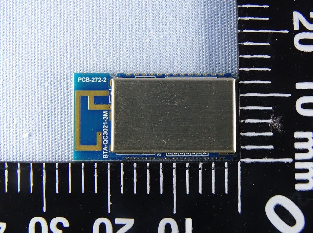
2AABGQ3031-3M
Dec 01, 2020BT Dual mode Module
Equipment Class
DTS - Digital Transmission System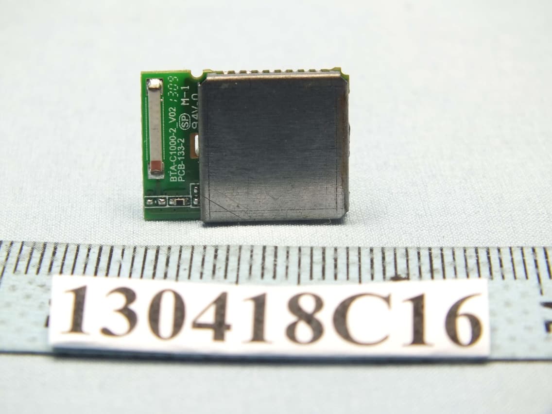
2AABGBTAC1000
May 29, 2013Bluetooth module
Equipment Class
DTS - Digital Transmission System