2AACD-POWERLINEECCOBar Code Reader
Feig Electronic GmbH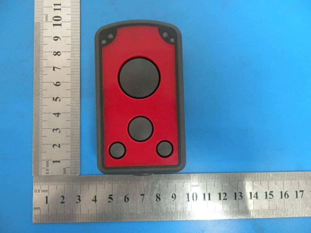
Click to zoom
Application Details
- Equipment Class
- DSS - Part 15 Spread Spectrum Transmitter
- Date of Grant
- Jun 19, 2013
- Application Purpose
- Original Equipment
- Date of Application
- Jun 19, 2013
- Equipment Note
- Bar Code Reader
- Frequency Range
- 2402.00000000 - 2480.00000000
- Company
- Feig Electronic GmbH
- Country
- Germany
Documents & Files
Document Text
Text extracted from the exhibit documents filed with the FCC. Open a document above to read the original.
Users Manual
powerLine ECCO user manual powerLine ECCO Bluetooth scanner can choose serial transmission or USB-HID , you can use bluetooth connect bluetooth Phone or PC Set HID mode : scan the barcode : AT#MT=0 (code 128) Set serial mode: scan the barcode: AT#MT=1 (code 128) 1, The buletooth gun key explain: a) The first key: power on and scan. Press the first key, you can hear the normal sound . then you can see the light flash on bluetooth gun , it means: the bluetooth startup ,you can connect the Phone or PC through setting b) The second key: sent data If you had beyond the bluetooth transmission distance, powerLine ECCO can store data , but when you come back in the valid range ,Bluetooth can be automatic connect, you can sent data by press the second key c) The third key: power off key If you press this key , the bluetooth gun close power 2, Test : Hold down the first key, keep 5 second, until the laser line appear. Then you can press the first key can scan barcode , but the data can not be transmission, it mean the bluetooth gun is good Delay shutdown function: when the bluetooth is not connected or it did not work, bluetooth scanner will dormancy after 30 second, 5 minute will be shutdown. 3, Indicator light: The left side is bluetooth indicator light, when lights flash , bluetooth isnot connection, when lights is keep, bluetooth is connected, you can scan the barcode , the data can be sent to the bluetooth Phones or PC or other bluetooth equipment. The right side is charge power light, the USB port only charge. connect the computer or power through USB cable, it can charge battery, the battery input 5V power, current 450 mA, if charge finished, light will become weak Bluetooth instructions: (connect Mobile phone) If the bluetooth barcode scanner need connect Mobile phone , you need choose serial transmission, you can print the barcode : AT#MT=1 ( Code 128 ) Then scan this barcode, the bluetooth barcode scanner will change serial transmission the mobile phones need has the bluetooth function, First use, the bluetooth gun and the mobile phone need to pairing. step is as follows: press first the key, the bluetooth gun is normal opens, bluetooth light star flash, Then open the bluetooth mobile phone, search buletooth equipment, it can search SCAN icon, and then begin connection, password is: "0000". Choice the serial ports , such as chioce COM9, open the software on Phone ,choice the corresponding serial ports COM9 ,choice: 9600, N, 8, 1. Press "CONNECT" or "OPEN", the buletooth gun light stop flash , the bluetooth phones and buletooth gun connect success, you can scan barcode, the data upload to serial software on the Phone Bluetooth instructions:(connect PC) Serial : First use, the bluetooth gun and PC need to pairing. step is as follows: press the first key, the bluetooth gun normal opens, bluetooth light star flash, Then insert bluetooth receiver in PC, search bluetooth equipment on PC, can search SCAN icon, and then connection, password is: "0000". Choice the serial port, such as chioce COM9, open the serial software on PC, choice the corresponding serial ports :COM9 ,choice: 9600, N, 8, 1. Press "CONNECT" or "OPEN" ,the buletooth gun light stop flash, buletooth gun connect to PC success, you can scan barcode, the data upload to serial software on PC This device complies with Part 15 of the FCC Rules. Operation is subject to the following two conditions: (1) this device may not cause harmful interference, and (2) this device must accept any interference received, including interference that may cause undesired operation. Changes or modifications not expressly approved by the party responsible for compliance could void the user's authority to operate the equipment。 Note: This equipment has been tested and found to comply with the limits for a Class B digital device, pursuant to part 15 of the FCC Rules. These limits are designed to provide reasonable protection against harmful interference in a residential installation. This equipment generates, uses and can radiate radio frequency energy and, if not installed and used in accordance with the instructions, may cause harmful interference to radio communications. However, there is no guarantee that interference will not occur in a particular installation. If this equipment does cause harmful interference to radio or television reception, which can be determined by turning the equipment off and on, the user is encouraged to try to correct the interference by one or more of the following measures: —Reorient or relocate the receiving antenna. —Increase the separation between the equipment and receiver. —Connect the equipment into an outlet on a circuit different from that to which the receiver is connected. —Consult the dealer or an experienced radio/TV technician for help. Trademark: PANMOBIL Name: Bar Code Reader Model Number: powerLine ECCO FCC ID: 2AACD-POWERLINEECCO
Cover Letter(s)
Advanced Panmobil Systems GmbH & Co. KG Federal Communications Commission Equipment Authorization Branch 7435 Oakland Mills Road Columbia, MD 21046 Request for Confidentiality Company name: Advanced Panmobil Systems GmbH & Co. KG FCC ID : 2AACD-POWERLINEECCO FCC Part 15 Certification Gentlemen, Pursuant to 47 CFR 0.457(d)(1)(ii) and 0.459 we hereby requests permanent confidentiality of the following documents for the subject application: Exhibit Type Description ☒ Schematics All circuitry of devices and component values ☒ Block Diagrams Details of device showing the frequency of all oscillators ☒ Operational Description Description of the circuit functions Note: Exhibit types that are commonly held confidential are: (1) Schematics, (2) Block Diagrams, (3) Bill Of Materials, (4) Operational Descriptions. Any exhibit NOT granted confidentiality is viewable on the FCC website as soon as a grant is issued. These documents contain detailed system and equipment description and related information about the product which we considers to be proprietary, confidential and a custom design and otherwise would not release to the general public. Since the design is a basis from which future technological products will evolve, we consider that this information would be of benefit to its competitors and that the disclosure of the information in these documents would give competitors an unfair advantage in the market. Yours sincerely, Signatory Name Zhang libo Position General manager Company Name Advanced Panmobil Systems GmbH & Co. KG Address Hansestrasse 91 D- 51149 Koeln Germany Tel 010-88840855 Fax 010-88840955 Email [email protected]
Cover Letter(s)
Advanced Panmobil Systems GmbH & Co. KG Date: 30.05.2013 Authority to Act as an Agent We declare that the following representative (agent) Name Mark Zhu Position Manager Company Name Shenzhen Certification Technology Service Co., Ltd. Address 2F, Building B, East Area of Nanchang Second Industrial Zone, Gushu 2 nd Road, Bao’an District, Shenzhen 518126, P.R. China Tel / Fax 0755-86375541/0755-26736857 Email [email protected] to act on our behalf on all matters concerning the application and documents submitted to PHOENIX TEST-LAB for product certification below Product Name Bar Code Reader Model Name powerLine ECCO Brand Name PANMOBIL Yours sincerely, Signatory Name Zhang libo Position General manager Company Name Advanced Panmobil Systems GmbH & Co. KG Address Hansestrasse 91 D- 51149 Koeln Germany Tel 010-88840855 Fax 010-88840955 Email [email protected] In case of FCC, we certify that we are not subject to a denial of Federal benefits, that include FCC benefits, pursuant to Section 5301 of the Anti-Drug Abuse Act of 1988, 21 U.S.C. §862 because of a conviction for possession or distribution of a controlled substance.
ID Label/Location Info
30mm 16mm Trademark: PANMOBIL Name: Bar Code Reader Model Number: powerLine ECCO FCC ID: 2AACD-POWERLINEECCO
ID Label/Location Info
Label Location
Internal Photos
ANTENNA
Test Report
Shenzhen Certification Technology Service Co., Ltd. 2F, Building B, East Area of Nanchang Second Industrial Zone, Gushu 2 nd Road, Bao'an District, Shenzhen 518126, P.R. China FCC ID: 2AACD-POWERLINEECCO Page 1 of 68 TEST REPORT FCC ID: 2AACD-POWERLINEECCO Applicant : Advanced Panmobil Systems GmbH & Co. KG Address : Hansestrasse 91 D- 51149 Koeln Germany Equipment Under Test (EUT): Name : Bar Code Reader Model : powerLine ECCO In Accordance with: FCC PART 15.247 Report No : STI130426061 Date of Test : May 19-28, 2013 Date of Issue : May 29, 2013 Test Result: PASS In the configuration tested, the EUT complied with the standards specified above Authorized Signature ___________________________ (Mark Zhu) General Manager The manufacture should ensure that all the products in series production are in conformity with the product sample detailed in this report. If the product in this report is used in any configuration other than that detailed in the report, the manufacturer must ensure the new system complies with all relevant standards. Any mention of Shenzhen Certification Technology Service Co., Ltd. Or test done by Shenzhen Certification Technology Service Co., Ltd. Approvals in connection with, distribution or use of the product described in this report must be approved by Shenzhen Certification Technology Service Co., Ltd. Approvals in writing. Report No.: STI130426061 FCC ID: 2AACD-POWERLINEECCO Page 2 of 68 Contents 1. General Information ...................................................................................................4 1.1. Description of Device (EUT) ...............................................................................4 1.2. Accessories of device (EUT) ...............................................................................4 1.3. Test Lab information ............................................................................................4 2. Summary of test ..........................................................................................................5 2.1. Summary of test result .........................................................................................5 2.2. Assistant equipment used for test.........................................................................5 2.3. Block Diagram .....................................................................................................5 2.4. Test mode .............................................................................................................6 2.5. Test Conditions.....................................................................................................6 2.6. Measurement Uncertainty (95% confidence levels, k=2) ....................................6 2.7. Test Equipment.....................................................................................................7 3. Maximum Peak Output power ..................................................................................8 3.1. Limit .....................................................................................................................8 3.2. Test Procedure ......................................................................................................8 3.3. Test Setup .............................................................................................................8 3.4. Test Result...........................................................................................................8 4. 20dB bandwidth ..........................................................................................................9 4.1. Limit .....................................................................................................................9 4.2. Test Procedure ......................................................................................................9 4.3. Test Result ............................................................................................................9 5. Carrier Frequency Separation.................................................................................13 5.1. Limit ...................................................................................................................13 5.2. Test Procedure ....................................................................................................13 5.3. Test Result ..........................................................................................................13 6. Number Of Hopping Channel..................................................................................15 6.1. Limit ...................................................................................................................15 6.2. Test Procedure ....................................................................................................15 6.3. Test Result ..........................................................................................................15 7. Dwell Time .................................................................................................................18 7.1. Test limit ............................................................................................................18 7.2. Test Procedure....................................................................................................18 7.3. Test Results ........................................................................................................18 8. Radiated emissions....................................................................................................18 8.1. Limit ...................................................................................................................29 8.2. Block Diagram of Test setup ..............................................................................30 8.3. Test Procedure ....................................................................................................30 8.4. Test Result ................…
Text truncated - open the document above for the full version.
Test Setup Photos
Conducted Emission Test Setup Radiated Emission Test Setup in Chamber
Contact Information
Applicant
Alwin Scheu(Product Manager)
Test Firm
Shenzhen Certification Technology Service Co., LtdMark Zhu
Technical Specifications
| # | Rule Parts | Frequency Range | Power Output |
|---|---|---|---|
| 1 | 15C | 2.40 GHz - 2.48 GHz | 1.67 mW |
Other Applications from Feig Electronic GmbH
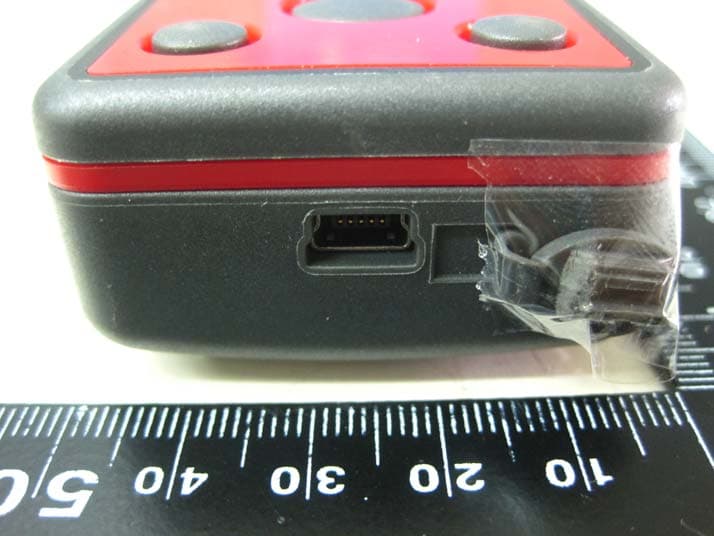
2AACD-EECCOPLUS
Nov 16, 2015powerlineECCO+
Equipment Class
DXX - Part 15 Low Power Communication Device Transmitter