2AAD8-WU112K150M High Gain Wireless USB Adapter
HAOLIYUAN (SHENZHEN) ELECTRONIC CO., LTD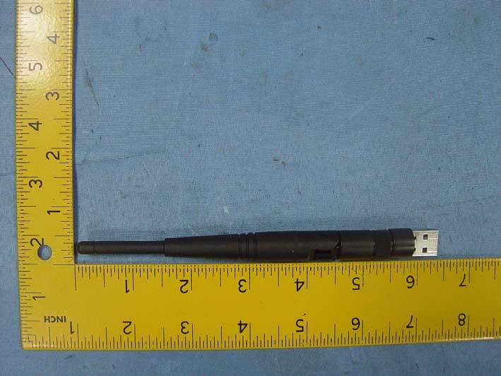
Click to zoom
Application Details
- Equipment Class
- DTS - Digital Transmission System
- Date of Grant
- Oct 13, 2014
- Application Purpose
- Original Equipment
- Date of Application
- Oct 13, 2014
- Equipment Note
- 150M High Gain Wireless USB Adapter
- Frequency Range
- 2412.00000000 - 2462.00000000
- Country
- China
Documents & Files
Document Text
Text extracted from the exhibit documents filed with the FCC. Open a document above to read the original.
Users Manual
1 / 13 Wireless 802.11b/g/n USB Adapter Quick Installation Guide 2 / 13 I. Driver Installation Please follow the following instructions to install your new wireless USB Adapter: 1. Insert the USB wireless network card into an empty USB 2.0 port of your computer when computer is switched on. Never use force to insert the card, if you feel it’s stuck, flip the card over and try again. 2. The following message will appear on your computer, click ‘Cancel / Close’. Under Windows XP Under Windows Vista and Windows 7 3 / 13 3. Insert the driver CD into your CD-ROM. You can see autorun screen below. if not, you can double click ‘autorun.exe ’ on CD. Click ‘Install Driver ’ to start the installation procedure. 4. Installation descriptions shown. Click I accept the of the license agreement , Click ‘Next’ to continue. 5. Show following window, Click ‘Next’ to continue. 4 / 13 6. Show following window, Click ‘Next’ to continue. 7. Show following window, Click ‘Install ’ to continue. 5 / 13 8. Show following window, click ‘Finish’ to finish the installation. II. Connecting to a Wireless Network 6 / 13 The Utility lets you connect to a wireless network, hotspot, access point (AP), or wireless router, and even lets you connect to the Internet. Follow the steps below to connect to a wireless network using the Utility. 1. Open the Utility by double-clicking on the Utility icon in the taskbar in the bottom right corner of your screen. 2. The Utility appears, by default connected to an available open wireless network. Check the name of the network to which you are connected. If this is the correct network, no further steps are required. 3. To connect to an alternative network, click the Available Networks button. 4. In the Available Networks window that appears, select the name of the network to which you are connecting. Then click the connect 7 / 13 icon and wait several seconds while the Utility sets up a connection. 5. The Utility automatically detects and displays the security settings of the network to which you are connecting in the Profile Settings screens. WPA-PSK or WPA2-PSK A. If the Utility shows that WPA-PSK or WPA2-PSK security is detected, click the right arrow to save your settings. B. In the screen that displays, in the 'WPA Preshared Key' field, type a security key, the same as that used by the AP or wireless 8 / 13 router to which you are connecting. Click the right arrow to save your settings and connect to the network. WEP A. If the Utility shows that WEP security is detected, click the right arrow to save your settings. B. In the 'WEP Key' field, type the same WEP key as that configured on the AP or wireless router to which you are connecting, and ensure that 'Default Tx Key' and 'Key Format' settings are also the same. Click the right arrow to save your settings and connect to the network. 9 / 13 802.1X, WPA, or WPA2 A. If the Utility shows that 802.1x, WPA, or WPA2 security is detected, click the right arrow to save your settings. B. Select the EAP Method (Extensible Authentication Protocol) and Tunnel Authentication method, and if required, the Tunnel ID method and Tunnel Mode, and enter the user name and password, using the settings provided by your organization's network administrator. Click the right arrow to save your settings. WAPI-PSK A. If the Utility shows that WAPI-PSK security is detected, click the right arrow to save your settings. 10 / 13 B. In the 'WPA Preshared Key' field, type a security key, and select a Key Format setting, the same as that used by the AP or wireless router to which you are connecting. Click the right arrow to save your settings and connect to the network. WAPI-CA A. If the Utility shows that WAPI-CA security is detected, click the right arrow to save your settings. B. If you have a WAPI certificate already installed, in the Select Mode field, select Auto and click the right arrow to save your settings and connect to the network. Otherwise, if there is no WAPI certificate in your system, go to Setting Up Enterprise 11 / 13 Wireless Security. No Security If your network has no security (not recommended), no further settings are required. Click the right arrow to save your settings and connect to the network 6. Once you are connected the Available Networks screen shows the status of your connection. 12 / 13 7. For more settings help, click view. 13 / 13 FCC STATEMENT 1. This device complies with Part 15 of the FCC Rules. Operation is subject to the following two conditions: (1) This device may not cause harmful interference. (2) This device must accept any interference received, including interference that may cause undesired operation. 2. Changes or modifications not expressly approved by the party responsible for compliance could void the user's authority to operate the equipment. Radiation Exposure Statement: This equipment complies with FCC radiation exposure requirement. The device can be used in portable exposure condition without RF striction
Cover Letter(s)
SCS-F18: Project and Product Certification Representative Authorization Letter Page 1 of 2 Rev 5.0 775 Montague Expressway Milpitas, CA 95035 Tel: 408-526-1188 Fax: 408-526-1088 Email: [email protected] Project and Product Certification Representative Authorization Letter Revision History Reason for Amendment (current / obsolete) From To Approved Date Initial Release (obsolete) 1.0 1.0 Nov-14-2006 Revised wording (obsolete) 1.0 2.0 Sept–25-2007 Updated company template (obsolete) 2.0 3.0 Jan-31-2012 Updated letter information (obsolete) 3.0 4.0 May-23-2014 Added FCC ID field (current) 4.0 5.0 Sept 16 2014 SCS-F18: Project and Product Certification Representative Authorization Letter Page 2 of 2 Rev 5.0 HAOLIYUAN (SHENZHEN) ELECTRONIC CO., LTD 2014-10-09 To: SIEMIC, INC. 775 Montague Expressway, Milpitas, CA 95035 USA Dear Sir/Madam, Re: Product Certification Representative Authorization Letter We, HAO LIYUAN (SHENZHEN) ELECTRONIC CO., LTD hereby authorize SIEMIC, Inc. to act as a Certification Body for certifying for the following project(s): Product Description: 150M High Gain Wireless USB Adapter Model name: WU112K FCC ID: 2AAD8-WU112K Sincerely, Client’s signature Client’s name / title: Joliam zhong / R&D Manager Contact information / address: 3/F Building A1, Junfeng Industrial Park, Yonghe Road, Fuyong, Baoan District, Shenzhen, Guangdong, China
Cover Letter(s)
SCS-F19: Confidentiality Request Letter Page 1 of 2 Rev 3.0 775 Montague Expressway Milpitas, CA 95035 Tel: 408-526-1188 Fax: 408-526-1088 Email: [email protected] Confidentiality Request Letter Revision History Reason for Amendment (current / obsolete) From To Approved Date Initial Release (obsolete) 1.0 1.0 Nov-14-2006 Adding CFR 2.459 (obsolete) 1.0 2.0 August – 11 - 2008 Updated company template & Added text box (current) 2.0 3.0 Jan-31-2012 SCS-F19: Confidentiality Request Letter Page 2 of 2 Rev 3.0 HAOLIYUAN (SHENZHEN) ELECTRONIC CO., LTD 2014-10-09 To: Federal Communications Commission Authorization and Evaluation Division 7435 Oakland Mills Road Columbia, MD Subject: Permanent Confidentiality Request for FCC ID: 2AAD8-WU11 2K We h ereby request confidential treatment of information accompanying this application as outlined below: - Block Diagram - Operational Description - Schematic The above materials contain trade secrets and proprietary information not customarily released to the public. The public disclosure of these materials may be harmful to the applicant and provide unjustified benefits to its competitors. The applicant understands that pursuant to Section 0.457 & 0.459 of the Rules, disclosure of this application and all accompanying documentation will not be made before the date of the Grant for this application. Sincerely, Client’s signature Client’s name / title: Joliam zhong / R&D Manager Contact information / address: 3/F Building A1, Junfeng Industrial Park, Yonghe Road, Fuyong, Baoan District, Shenzhen, Guangdong, China
Cover Letter(s)
HAOLIYUAN (SHENZHEN) ELECTRONIC CO., LTD To: Federal Communications Commission Authorization and Evaluation Division 7435 Oakland Mills Road Columbia, MD FCC ID: 2AAD8-WU112K To Whom It May Concern: This letter is to ascertain that HAOLIYUAN (SHENZHEN) ELECTRONIC CO., LTD (Product: 150M High Gain Wireless USB Adapter Model name: WU112K has been the units used for conducting FCC compliance testing, the DoC part will be tested by FCC recognized test lab. If you have any question or concerns, pls. contact us. Sincerely, Client’s signature Client’s name / title: Joliam zhong / R&D Manager Contact information / address: 3/F Building A1, Junfeng Industrial Park, Yonghe Road, Fuyong, Baoan District, Shenzhen, Guangdong, China
ID Label/Location Info
FCC ID: 2AAD8-WU112K
Internal Photos
Antenna
RF Exposure Info
FCC ID : 2AAD8-WU112K Portable device According to §15.247(e)(i) and §1.1307(b)(1), systems operating under the provisions of this section shall be operated in a manner that ensures that the public is not exposed to radio frequency energy level in excess of the Commission’s guidelines. According to KDB 447498 D01 General RF Exposure Guidance v05, section 4.3.1 The 1-g and 10-g SAR test exclusion thresholds for 100 MHz to 6 GHz at test separation distances ≤ 50 mm are determined by: [(max. power of channel, including tune-up tolerance, mW)/(min. test separation distance, mm)] · [√f(GHz)] ≤ 3.0 for 1-g SAR and ≤ 7.5 for 10-g extremity SAR, 16 where f(GHz) is the RF channel transmit frequency in GHz Power and distance are rounded to the nearest mW and mm before calculation 17 The result is rounded to one decimal place for comparison The test exclusions are applicable only when the minimum test separation distance is ≤ 50 mm and for transmission frequencies between 100 MHz and 6 GHz. When the minimum test separation distance is < 5 mm, a distance of 5 mm is applied to determine SAR test exclusion. The test was performed with 802.11b Frequency (MHz) Average Output Power(dBm) Average Output Power(mW) Calculation Value Threshold Value 2412 9.20 8.32 2.58 3.0 2437 9.14 8.20 2.56 3.0 2462 9.26 8.43 2.65 3.0 The test was performed with 802.11g Frequency (MHz) Average Output Power(dBm) Average Output Power(mW) Calculation Value Threshold Value 2412 7.23 5.28 1.64 3.0 2437 7.12 5.15 1.61 3.0 2462 7.46 5.57 1.75 3.0 The test was performed with 802.11n (20MHz) Frequency (MHz) Average Output Power(dBm) Average Output Power(mW) Calculation Value Threshold Value 2412 7.26 5.32 1.65 3.0 2437 6.92 4.92 1.54 3.0 2462 6.63 4.60 1.44 3.0 The test was performed with 802.11n (40MHz) Frequency (MHz) Average Output Power(dBm) Average Output Power(mW) Calculation Value Threshold Value 2422 4.88 3.08 0.96 3.0 2437 4.82 3.03 0.95 3.0 2452 4.83 3.04 0.95 3.0 Threshold at which no SAR required is ≤ 3.0 for 1-g SAR, Separation distance is 5mm. Conclusion: No SAR is required. SIMULTANEOUS TRANSMISSION EVALUATION N/A
Test Report
Page 1 of 104 FCC ID: 2AAD8-WU112K ACCURATE TECHNOLOGY CO., LTD Report No.: ATE20141832 APPLICATION CERTIFICATION FCC Part 15C On Behalf of HAOLIYUAN (SHENZHEN) ELECTRONIC CO., LTD 150M High Gain Wireless USB Adapter Model No.: WU112K FCC ID: 2AAD8-WU112K Prepared for : HAOLIYUAN (SHENZHEN) ELECTRONIC CO., LTD Address : 3/F, Building A1, Junfeng Industrial Park, Yonghe Road, Fuyong, Bao'an District, Shenzhen, Guangdong,China Prepared by : ACCURATE TECHNOLOGY CO., LTD Address : F1, Bldg. A, Changyuan New Material Port, Keyuan Rd. Science & Industry Park, Nanshan, Shenzhen, Guangdong P.R. China Tel: (0755) 26503290 Fax: (0755) 26503396 Report Number : ATE20141832 Date of Test : Sep 21-Oct 09,2014 Date of Report : Oct 09,2014 Page 2 of 104 FCC ID: 2AAD8-WU112K ACCURATE TECHNOLOGY CO., LTD Report No.: ATE20141832 TABLE OF CONTENTS Description Page Test Report Certification 1. GENERAL INFORMATION .......................................................................................................... 5 1.1. Description of Device (EUT)....................................................................................................................5 1.2. Carrier Frequency of Channels .................................................................................................................6 1.3. Special Accessory and Auxiliary Equipment ...........................................................................................6 1.4. Description of Test Facility ......................................................................................................................6 1.5. Measurement Uncertainty.........................................................................................................................7 2. MEASURING DEVICE AND TEST EQUIPMENT ..................................................................... 8 3. OPERATION OF EUT DURING TESTING ................................................................................. 9 3.1. Operating Mode ........................................................................................................................................9 3.2. Configuration and peripherals ..................................................................................................................9 4. TEST PROCEDURES AND RESULTS ....................................................................................... 10 5. 6DB&20DB BANDWIDTH MEASUREMENT ........................................................................... 11 5.1. Block Diagram of Test Setup..................................................................................................................11 5.2. The Requirement For Section 15.247(a)(2) ............................................................................................11 5.3. EUT Configuration on Measurement .....................................................................................................11 5.4. Operating Condition of EUT ..................................................................................................................11 5.5. Test Procedure ........................................................................................................................................11 5.6. Test Result ..............................................................................................................................................12 6. MAXIMUM OUTPUT POWER.................................................................................................... 25 6.1. Block Diagram of Test Setup..................................................................................................................25 6.2. The Requirement For Section 15.247(b)(3)............................................................................................25 6.3. EUT Configuration on Measurement .....................................................................................................25 6.4. Operating Condition of EUT ..................................................................................................................25 6.5. Test Procedure ........................................................................................................................................25 6.6. Test Result ..............................................................................................................................................26 7. POWER SPECTRAL DENSITY MEASUREMENT.................................................................. 33 7.1. Block Diagram of Test Setup..................................................................................................................33 7.2. The Requirement For Section 15.247(e).................................................................................................33 7.3. EUT Configuration on Measurement .....................................................................................................33 7.4. Operating Condition of EUT ..................................................................................................................33 7.5. Test Procedure ........................................................................................................................................33 7.6. Test Result ..............................................................................................................................................34 8. BAND EDGE COMPLIANCE TEST ........................................................................................... 41 8.1. Block Diagram of Test Setup..................................................................................................................41 8.2. The Requirement For Section 15.247(d) ................................................................................................41 8.3. EUT Configuration on Measurement ..........................................................................…
Text truncated - open the document above for the full version.
Contact Information
Applicant
Joliam Zhong(R&D Manager)
Test Firm
Accurate Technology Co., Ltd.Sean Liu
Technical Specifications
| # | Rule Parts | Frequency Range | Power Output |
|---|---|---|---|
| 1 | 15C | 2.41 GHz - 2.46 GHz | 8.43 mW |
Other Applications from HAOLIYUAN (SHENZHEN) ELECTRONIC CO., LTD
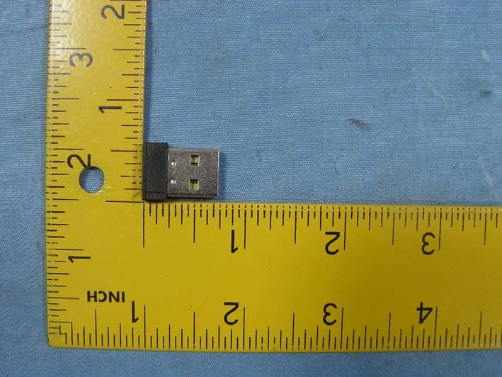
2AAD8-WU110K
Oct 13, 2014150M Mini Wireless USB Adapter
Equipment Class
DTS - Digital Transmission System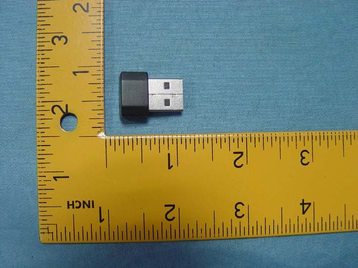
2AAD8-WU331
Jun 24, 2014300M Mini Wireless USB Adapter
Equipment Class
DTS - Digital Transmission System