2AAEEDMD1048BLKSmart Scale
Shenzhen Belter Health Measurement and Analysis Technology Co., Ltd.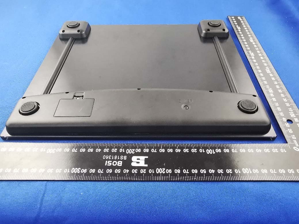
Click to zoom
Application Details
- Equipment Class
- DTS - Digital Transmission System
- Date of Grant
- May 31, 2020
- Application Purpose
- Original Equipment
- Date of Application
- May 31, 2020
- Equipment Note
- Smart Scale
- Frequency Range
- 2402.00000000 - 2480.00000000
- Country
- China
Documents & Files
Document Text
Text extracted from the exhibit documents filed with the FCC. Open a document above to read the original.
Users Manual
Before Using Scale 1. Remove all packaging materials. 2. Remove the isolator tab from the battery compartment – without opening the battery cover at the bottom of the scale, gently pull out the isolator tab. (In case the tab cannot be pulled out, remove the screw from the battery cover and remove the cover. Gently pull out the isolator tab. Ensure the battery is installed correctly. Replace the battery cover and tighten the screw again.) 3. For best accuracy, place scale on tile or hardwood oor, rather than uneven, exible, or soft ooring (such as carpet). SPECIFICATIONS ⚫ Equipped with a high-precision “Strain-Gauge” sensor ⚫ Product Size:365X315mm ⚫ LCD size:90X40mm ⚫ Capacity 250kg (550lbs) ⚫ Division 100g/0.2lb ⚫ Tap-on start ⚫ Automatic zero reset ⚫ Overload indicator ⚫ Automatic switch off a. Startup shows 0.0, if the user has no operation, the scale will automatically shut down after about 15S. b. After the weighing weight is locked, if the user does not get off the scale, the body will automatically shut down after about 10S. c. After the weighing weight is locked, if the user comes down from the scale, the body will automatically shut down after about 10S. ⚫ LCD display Battery Replacement If battery is low and needs to be replaced, “Lo” will appear on screen. Please loosen the screw and remove with the battery cover. Replace the old battery with three new AAA batteries. Clean the batteries contacts and also those of the device prior to battery installation. Ensure the batteries are installed correctly with regard to polarity, then replace the batteries cover and tighten the screw again. Remove batteries from the scale if it will not be used for an extended period of time. Remove used batteries promptly. Properly dispose of the old battery. Do not attempt to open the scale or to remove any components. Servicing should be done by qualied technicians only. Switch Unit Press the button on the back to switch. Lb or kg is available. INSTRUCTIONS FOR USE Connectivity status indicator lb unit kg unit Helpful Hints Bariatric scale is a precise measuring instrument that is most accurate when weighing a stationary object. To ensure the most accurate readings always try to stand on the same area of the scale platform and do not move. Should the weight on the scale exceed the scale’s capacity, you may see an error message ”Err.” Electronic sensors are sensitive. Be careful not to drop or jar the scale. Place it gently onto oor surface, and store where it will be protected from impact. The scale is an electronic instrument and should never be submerged in water. Clean with damp cloth only. THINGS YOU SHOULD KNOW ABOUT MANAGING YOUR WEIGHT Diet, exercise, and determination all play a part in effective weight management. Your scale is the tool that lets you chart your progress, and measure your success, whether your goal is weight loss, weight gain, or maintaining your current weight. Because weight varies, as explained below, focus on the progression and sustained 1ong-term changes rather than on exact day-to-day readings. When you're dieting and exercising, small, fluctuating weight gains and losses are common. Common Causes of Weight Fluctuations (during the day, and day-to-day) • Water retention and weight gain from consumption of large meals • Water retention from salt and carbohydrate intake • Muscle buildup (muscle weighs more than fat) from strenuous resistance training • Weight loss caused by dehydration due to illness, low uid intake or strenuous exercise • Temporary weight gains and losses from menstrual cycle Weight Maintenance vs. Weight Loss/Gain Get into the habit of weighing yourself no more than once a week when you’re on a weight management program. Weighing in at consistent intervals will give you the most accurate picture of your progress, eliminating many short-term, unrelated weight changes. Follow These Simple Rules • Weigh yourself once a week. • Weigh yourself on the same day of the week. • Weigh yourself at the same time of day. • Weigh yourself wearing the same clothes. • Weigh yourself in the same place. • Weigh yourself on the same scale. Weight fluctuates more when a person is overweight or underweight. When the goal is to maintain current weight, weighing yourself more than once a week is a good way to stay on track. Remember: A scale is an essential tool in any weight management program, but it only records your progress. Exercise, diet and determination are what you need to reach your goal. Note: This equipment has been tested and found to comply with the limits for a Class B digital device, pursuant to part 15 of the FCC Rules. These limits are designed to provide reasonable protection against harmful interference in a residential installation. This equipment generates, uses and can radiate radio frequency energy and, if not installed and used in accordance with the instructions, may cause harmful interference to radio communications. However, there is no guarantee that interference will not occur in a particular installation. If this equipment does cause harmful interference to radio or television reception,which can be determined by turning the equipment off and on, the user is encouraged to try to correct the interference by one or more of the following measures: —Reorient or relocate the receiving antenna. —Increase the separation between the equipment and receiver. —Connect the equipment into an outlet on a circuit different from that to which the receiver is connected. —Consult the dealer or an experienced radio/TV technician for help. This device complies with Part 15 of the FCC Rules. Operation is subject to the following two conditions: (1) This device may not cause harmful interference. (2) This device must accept any interference received, including interference that may cause undesired operation. NOTE: The manufacturer is not responsible for any radio or TV interference caused by unauthorized modifications to this equipment. Such modifications could…
Text truncated - open the document above for the full version.
External Photos
Annex No.: BL-SZ2050353-AW 1 / 3 EUT EXTERNAL PHOTOS FRONT VIEW OF EUT REAR VIEW OF EUT Annex No.: BL-SZ2050353-AW 2 / 3 LEFT SIDE VIEW OF EUT RIGHT SIDE OF EUT Annex No.: BL-SZ2050353-AW 3 / 3 TOP VIEW OF EUT BOTTOM VIEW OF EUT
ID Label/Location Info
Label Location
Internal Photos
Annex No.: BL-SZ2050353-AI 1 / 2 EUT INTERNAL PHOTOS EUT UNCOVER VIEW EUT UNCOVER VIEW Annex No.: BL-SZ2050353-AI 2 / 2 MAIN BOARD TOP VIEW MAIN BOARD REAR VIEW PCB Antenna RF Chip
RF Exposure Info
RF Exposure Evaluation for FCC ID: 2AAEEDMD1048BLK Refer user manual this device is a Smart Scale, and this device was designed used in portable devices that the minimum distance between human’s body is 5mm. Based on the 47CFR 2.1093, this device belongs to portable device. The definition of the category as f ollowing: Portable Derives: CFR Title 47 §2.1093(b) (b) For purposes of this section, a portable device is defined as a transmitting device designed to be used so that the radiating structure(s) of the device is/are within 20 centimeters of the body of the user. FCC KDB 447498 D01 General RF Exposur e Guidance v06 Limit Unless specifically required by the published RF exposure KDB procedures, standalone 1‐g head or body and 10‐g extremity SAR evaluation for general population exposure conditions, by measurement or numerical simulation, is not required when the corresponding SAR Test Exclusion Threshold condition, listed below, is sa tisfied. These test exclusion conditions are based on source‐ based time‐averaged maximum conducted output power of the RF channel requiring evaluation, adjusted for tune‐up tolerance, and the minimum test separation distance required for the exposure conditions. The minimum test separation distance is determined by the smallest distance from the an tenna and radiating structures or outer surface of the device, according to the host form factor, exposure conditions and platform requirements, to any part of the body or extremity of a user or bystander. The 1‐g and 10‐g SAR test exclusion thresholds for 100 MHz to 6 GHz at te st separation distances ≤ 50 mm are determined by: [(max. power of channel, including tune‐up tolerance, mW) / (min. test separation distance, mm)] · [√f(GHz) ] ≤ 3.0 for 1‐g SAR and ≤ 7.5 for 10‐g extremity SAR Where • f (GHz) is the RF channel transmit fr equency in GHz • Power and distance are rounded to the nearest mW and mm before calculation • The result is rounded to one decimal place for comparison The test exclusions are applicable only when the minimum test separation distance is ≤ 50 mm and for transmission frequencies between 100 MHz and 6 GHz. When th e minimum test separation distance is < 5 mm, a distance of 5 mm is applied to determine SAR test exclusion. Test data BLUETOOTH Mode GFSK (BLE) Low Channel Middle Channel High Channel Peak Power (dBm) 2.50 2.50 2.38 Note: This report listed the worst case peak power value, please refer to RF test report for more details. Tune-up power Mode Range (dBm) Bluetooth 2.00-3.00 FCC exclusion condition= [2 mW/5 mm] · [√2.48 GHz] = 0.63 < 3.0 RF Exposure Evaluation Result: Pass Note: More power data, Please refer to the RF report.
Test Report
Report No.: BL-SZ2050353-601 2 / 50 Revision History Version Issue Date Revisions Content Rev. 01 May 28, 2020 Initial Issue TABLE OF CONTENTS 1 ADMINISTRATIVE DATA (GENERAL INFORMATION) .......................................................................... 5 1.1 Identification of the Testing Laboratory ....................................................................................... 5 1.2 Identification of the Responsible Testing Location ...................................................................... 5 1.3 Laboratory Condition ................................................................................................................... 5 1.4 Announce .................................................................................................................................... 5 2 PRODUCT INFORMATION ...................................................................................................................... 6 2.1 Applicant Information ................................................................................................................... 6 2.2 Manufacturer Information ............................................................................................................ 6 2.3 Factory Information ..................................................................................................................... 6 2.4 General Description for Equipment under Test (EUT) ................................................................ 6 2.5 Technical Information .................................................................................................................. 7 2.6 Additional Instructions ................................................................................................................. 8 3 SUMMARY OF TEST RESULTS .............................................................................................................. 9 3.1 Test Standards ............................................................................................................................ 9 3.2 Verdict ......................................................................................................................................... 9 4 GENERAL TEST CONFIGURATIONS ................................................................................................... 10 4.1 Test Environments .................................................................................................................... 10 4.2 Test Equipment List ................................................................................................................... 10 4.3 Measurement Uncertainty ......................................................................................................... 11 4.4 Description of Test Setup .......................................................................................................... 12 4.4.1 For Antenna Port Test ............................................................................................................... 12 4.4.2 For AC Power Supply Port Test ................................................................................................ 12 4.4.3 For Radiated Test (Below 30 MHz) ........................................................................................... 13 4.4.4 For Radiated Test (30 MHz-1 GHz) .......................................................................................... 13 4.4.5 For Radiated Test (Above 1 GHz) ............................................................................................. 14 4.5 Measurement Results Explanation Example ............................................................................. 15 4.5.1 For conducted test items: .......................................................................................................... 15 Report No.: BL-SZ2050353-601 3 / 50 4.5.2 For radiated band edges and spurious emission test: ............................................................... 15 5 TEST ITEMS ........................................................................................................................................... 16 5.1 Antenna Requirements .............................................................................................................. 16 5.1.1 Relevant Standards ................................................................................................................... 16 5.1.2 Antenna Anti-Replacement Construction .................................................................................. 16 5.1.3 Antenna Gain ............................................................................................................................ 16 5.2 Output Power ............................................................................................................................ 17 5.2.1 Test Limit ................................................................................................................................... 17 5.2.2 Test Setup ................................................................................................................................. 17 5.2.3 Test Procedure .......................................................................................................................... 17 5.2.4 Test Result ................................................................................................................................ 18 5.3 Occupied Bandwidth ................................................................................................................. 19 5.3.1 Limit ........................................................................................................................................... 19 5.3.2 Test Setup ................................................................................................................................. 19 5.3.3 Test Procedure ...................................…
Text truncated - open the document above for the full version.
Test Setup Photos
Annex No.: BL-SZ2050353-AR TEST SETUP PHOTOS 1 Radiated Test Photo Below 30 MHz 30 MHz-1 GHz Annex No.: BL-SZ2050353-AR Close-Up Above 1GHz Annex No.: BL-SZ2050353-AR Close-Up 2 Conducted Test Photo Conducted Test
Contact Information
Applicant
Ming Pang
Test Firm
Shenzhen BALUN Technology Co., Ltd.Hanson Lin
[email protected]86-755-66833830
Technical Specifications
| # | Rule Parts | Frequency Range | Power Output |
|---|---|---|---|
| 1 | 15C | 2.40 GHz - 2.48 GHz | 1.78 mW |
Other Applications from Shenzhen Belter Health Measurement and Analysis Technology Co., Ltd.
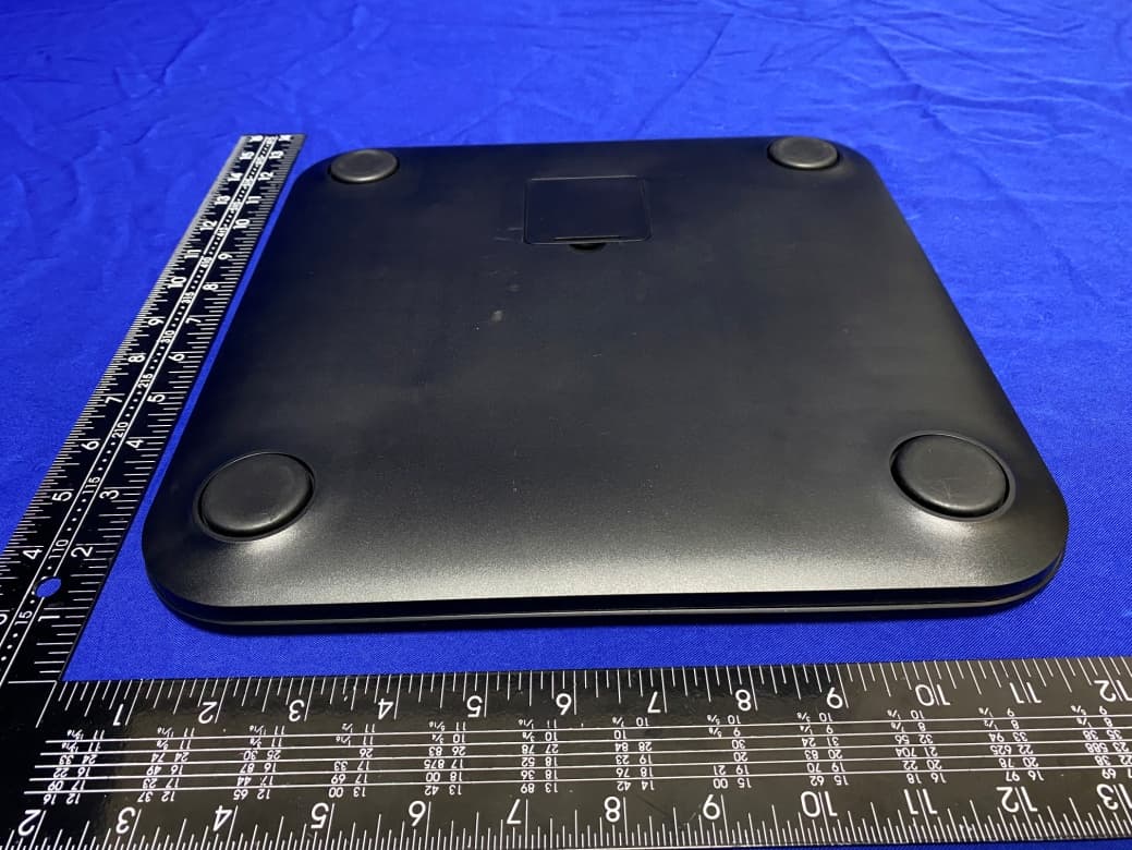
2AAEEEF916B4
Jul 12, 2021Body composition scale
Equipment Class
DTS - Digital Transmission System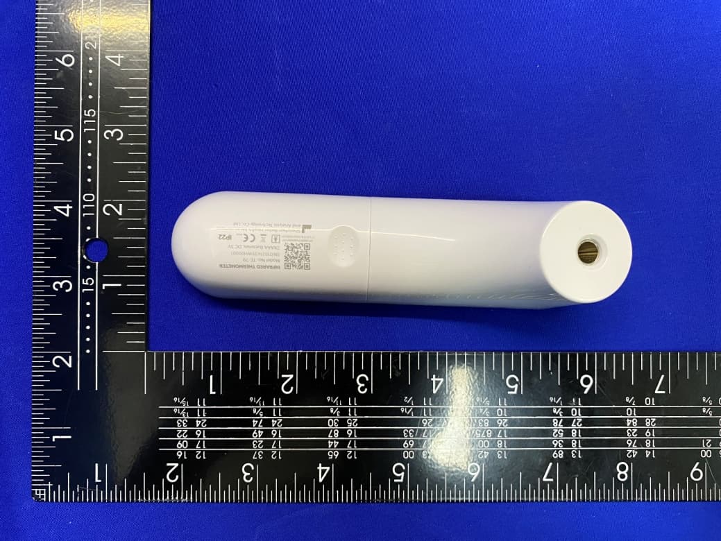
2AAEETE79
May 27, 2021Infrared Thermometer
Equipment Class
DTS - Digital Transmission System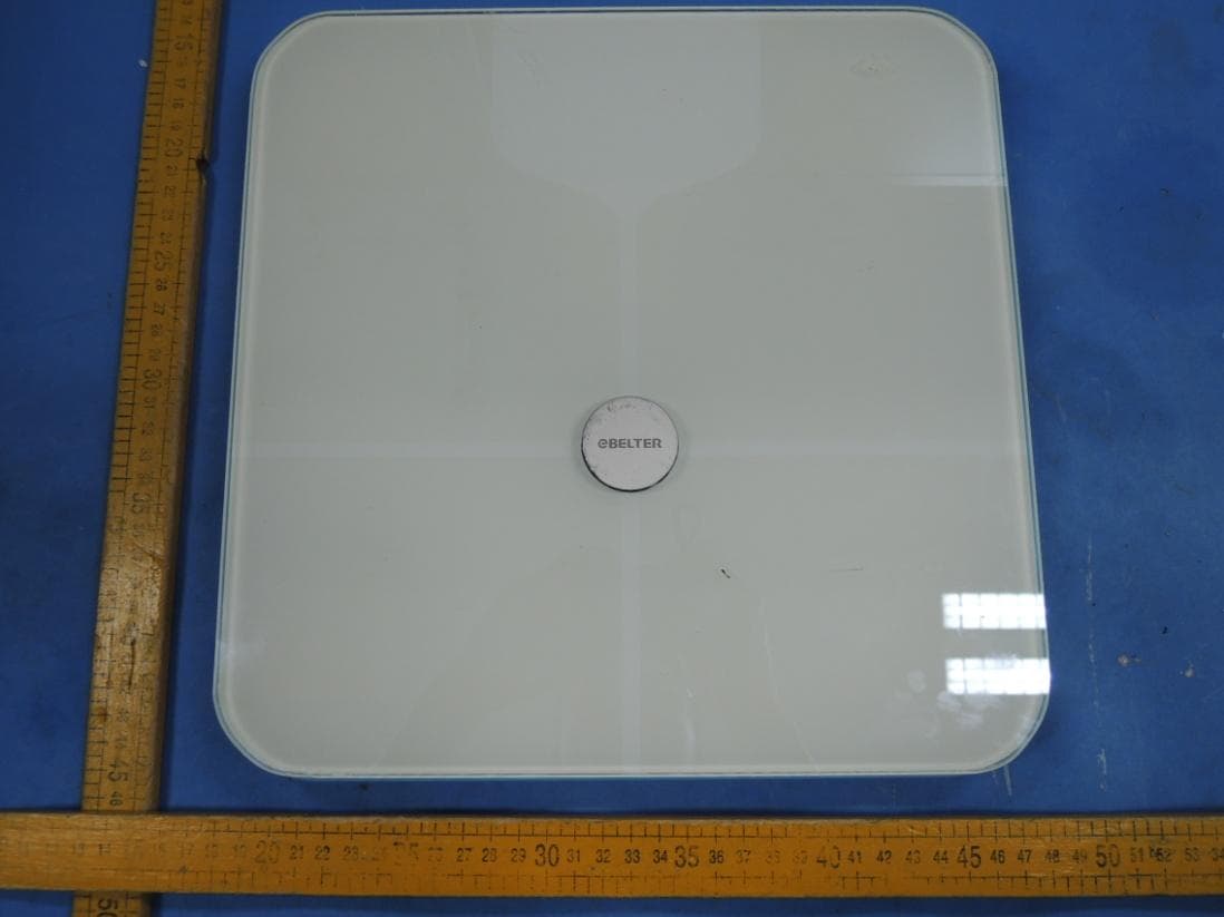
2AAEEEIVSCB
Nov 17, 2015Fat scale
Equipment Class
DTS - Digital Transmission System
2AAEEEIVSCK
Nov 17, 2015Kitchen scale
Equipment Class
DTS - Digital Transmission System
2AAEEE10B4
Nov 03, 2015Blood Pressure Meter
Equipment Class
DTS - Digital Transmission System