2AAGE-257Wireless Module
Chengdu Vantron Technology Co., Ltd.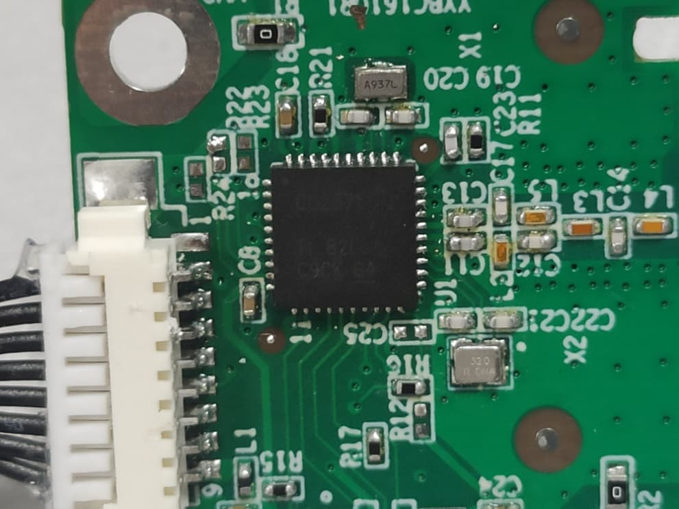
Click to zoom
Application Details
- Equipment Class
- DXX - Part 15 Low Power Communication Device Transmitter
- Date of Grant
- Feb 17, 2022
- Application Purpose
- Original Equipment
- Date of Application
- Feb 16, 2022
- Equipment Note
- Wireless Module
- Frequency Range
- 2450.00000000 - 2457.00000000
- Country
- China
Documents & Files
Document Text
Text extracted from the exhibit documents filed with the FCC. Open a document above to read the original.
Users Manual
ZB-HD-ANT-257 Hardware User Manual Product Version: 1.0 Date: 2021-12-14 For any question, please contact Chengdu Vantron Technology, Ltd. Copyright © Vantron Technology, Ltd. All rights reserved. Change History This table describes the version and release date. Rev. DateDescriptionAuthor 1.0 2021-12-14 First release.Cong Yang 2.0 2022-01-07 Modify product parameterCong Yang Foreword Copyright While all information contained herein have been carefully checked to assure its accuracy in technical details and printing, Vantron assumes no responsibility resulting from any error or features of this manual, or from improper uses of this manual or the software. Please contact our technical department for relevant operation solutions if there is any problem that cannot be solved according to this manual. Vantron reserves all rights of this manual, including the right to change the content, form, product features, and specifications contained herein at any time without prior written notice. The trademarks and registered trademarks in this manual are properties oftheir respective owners. No part of this manual may be copied, reproduced, translated or sold. No changes or other purposes are permitted without the prior writtenconsent of Vantron. Vantron reserves the right of all publicly-released copies of this manual. Symbol Conventions The symbols that may be found in this document are defined as follows. Symbol TypeDescription Notice Important information and regulations Caution Caution for latent damage to system or harm to personnel Statement & Disclaimer It is recommended to read and comply withthis manual which provides important guidance and helps decreasing the dangerof injury, electric shock, fire,or any damage to the device. Vantron assumes no legal liability of accidents resulting from failure ofconforming to the safety instructions. Limitation of Liability/Non-warranty For direct or indirect damage to this device or other devices of Vantron caused by failure of conforming to this manualor the safety instructions on device label, Vantron assumes neither warranty nor legal liability even if the device is still under warranty. The device should be installed, debugged andmaintained by professionals. The outside antennas are not permittedto be installed or to be changed by non-professionals. To run the device normally, only specified antennas are approved to be assembled together by professionals. Unit shall be used with indoor-use antenna only. No antenna for this unit canbe installed outdoor. Safety Instructions Keep and comply with all operation instructions, warnings, and information. Pay attention to warnings on this device. Read the following precautions so as to decrease the danger of injury, electric shock, fire, or any damage to the device. Operations and service instructions are provided with the equipment. Unit shall be used with indoor-use antenna only. No antenna for this unit canbe installed outdoor. The maximum operation temperature is 85°C. Precautions Pay attention to the product labels/safety instructions printed on silk screens. Do not try repairing this product unless declared in this manual. Keep away from heat source, such as heater, heat dissipater, or engine casing. Do not insert other items into the slot (if any) of this device. Ensure ventilation of the ventilation slot. System fault may arise if other items are inserted into this device. Installation: ensure correct installation according to instructions from the manufacturer with recommended installation tools. Ensure ventilation and smoothness according to relevant ventilation standards. Safety Instructions for Power Cables and Accessories Use Proper power source only. Start only with power source that satisfies voltage label and the voltage necessary according to this manual. Please contact technical support personnel of Vantron for any uncertainty about the requirements of necessary power source. Use tested power source. This product still contains a button lithium batteryasa real-time clock after its external power source is removed and therefore should not be short-circuited during transportation or placed under high temperature. Place cables properly: Do not place cables at any place with extrusion danger. Cleaning Instructions Please power off before cleaning the device. Do not use spray detergent. Clean with a damp cloth. Do not try cleaning exposed electronic components unless with a dust collector. Support for special fault: Power off and contact technical support personnel of Vantron in case of the following faults: The device is damaged. The temperature is excessively high. Fault is still not solved after operations according to the manual. Contents 1INTRODUCTION .......................................................................................................................................... 1 1.1 P RODUCTDESCRIPTION ................................................................................................................................ 1 1.2 C ONNECTORDESCRIPTION ........................................................................................................................... 1 2OVERVIEW .................................................................................................................................................... 2 2.1 I NTRODUCTION ............................................................................................................................................ 2 2.2 S PECIFICATIONS ............................................................................................................................................ 2 3 HARDWAREINSTRUCTIONS ..................................................................................................................... 3 3.1 A PPEARANCE ................................................................................................................................................ 3 3.2…
Text truncated - open the document above for the full version.
Cover Letter(s)
Chengdu Vantron Technology Co., Ltd.C5266091_X9_Ed.2 1/1 Modular Transmit ter Approval Request Federal Communications Commission Equipment Authorization Branch 7435 Oakland Mills Road Columbia, MD 21046 Company name: Chengdu Vantron Technology Co., Ltd. FCC ID: 2AAGE-257 Gentlemen, In accordance with 47CFR 15.212 Modular Transmitters and KDB 996369 D01 ‘Module Certification Guide v02’. FCC ID 2AAGE-257 has been examined against the following requirements. Items to be covered by Single modular transmitters. Requirement per 15.212 and KDB 996369 D01 ‘Modular Certification Guide v02 Explanation from Grantee (do not write yes/no, but explain why product complies/how it is achieved) 1.The radio elements must have the radio frequency circuitry shielded. Physical components and tuning capacitor(s) may be located external to the shield, but must be on the module assembly No,devicedoesnothaveashield. 2.The module must have buffered modulation/data inputs to ensure that the device will comply with Part 15 requirements with any type of input signal The modular has buffered data inputs, It is integrated in chip 3.The module must contain power supply regulation on the module Themodularhaspowersupply regulation 4.The module must contain a permanently attached antenna, or contain a unique antenna connector, and be marketed and operated only with specific antenna(s), per Sections 15.203, 15.204(b), 15.204(c), 15.212(a), 2.929(b) Antenna is independent fixed 5.The module must demonstrate compliance in a stand- alone configuration All power lines derived from the host device are regulated before energizing other circuits internal 6.The module must be labelled with its permanently affixed FCC ID label, or use an electronic display (See KDB Publication 784748 about labelling requirements) The label is independent fixed 7.The module must comply with all specific rules applicable to the transmitter including all the conditions provided in the integration instructions by the grantee Compliant with all applicable FCC rules,Detail instructions are given in the User manual 8.The module must comply with RF exposure requirements low power portable use, it can be operatedandinstalledwithout restriction.PleaseseetheMPE evaluation. Chengdu Vantron Technology Co., Ltd.C5266091_X9_Ed.2 1/1 Items to be covered by Split modular transmitters. Requirement per 15.212 and KDB 996369 D01 ‘Modular Certification Guide v02 Explanation from Grantee (do not write yes/no, but explain why product complies/how it is achieved) 9.Split modular transmitters must meet all the requirements of a single modular in above item1 and 5 for single modular approval requirements. Notapplicable. 10. Only the radio front end must be shielded. The physical crystal and tuning capacitors may be located external to the shielded radio elements. The interface between the split sections of the modular system must be digital with a minimum signaling amplitude of 150 mV peak-to-peak. Notapplicable. 11. Control information and other data may be exchanged between the transmitter control elements and radio front end. Notapplicable. 12. The sections of a split modular transmitter must be tested installed in a host device(s) similar to that which is representative of the platform(s) intended for use. Notapplicable. 13. Manufacturers must ensure that only transmitter control elements and radio front end components that have been approved together are capable of operating together. The transmitter module must not operate unless it has verified that the installed transmitter control elements and radio front end have been authorized together. Manufacturers may use means including, but not limited to, coding in hardware and electronic signatures in software to meet these requirements, and must describe the methods in their application for equipment authorization. Notapplicable. A limited modular approval (LMA) may be granted for single or split modular transmitters that comply partially with requirements above. Name:Xi WangDate: 2022/2/16 Title: VP Signature of applicant
External Photos
1 APPENDIX B. PHOTOGRAPHS OF EUT Photos of EUT EUT-1 EUT-2 EUT-3 EUT-4 Antenna RFIC EUT-5 ----------- End of Report -----------
ID Label/Location Info
Labellocation:
Internal Photos
1 APPENDIX B. PHOTOGRAPHS OF EUT Photos of EUT EUT-1 EUT-2 EUT-3 EUT-4 Antenna RFIC EUT-5 ----------- End of Report -----------
Test Report
Page 1 of 44 Test Report Verified code: Report No.: E202111247365-1-G1 Customer: Chengdu Vantron Technology Co., Ltd. Address: No.5 GaoPeng Road, Hi-Tech Zone, Chengdu, SiChuan, P.R. China 610045 Sample Name: Wireless Module Sample Model: VT-ANT-257 Receive Sample Date: Nov.26,2021 Test Date: Dec.20,2021 ~ Dec.27,2021 Reference Document: CFR 47, FCC Part 15 Subpart C RADIO FREQUENCY DEVICES: Subpart C—Intentional Radiators Test Result: Pass Prepared by: Reviewed by: Approved by: GUANGZHOU GRG METROLOGY & TEST CO., LTD Issued Date: GUANGZHOU GRG METROLOGY & TEST CO., LTD. Address: No.163, Pingyun Road, West of Huangpu Avenue, Guangzhou, Guangdong, China Tel:(+86)400-602-0999 FAX:(+86)020-38698685 Web:http://www.grgtest.com 736893 2022-02-11 Report No.: E202111247365-1-G1 Page 2 of 44 REVISION HISTORY Rev. Report No. Revisions Effect Page Revised By 00 E202111247365-1 Initial Issue ALL Yu Shanshan 01 E202111247365-1-G1 Update See below Yu Shanshan Rev.01: 1. This report replaces the original report E202111247365-1 (issue date:2022-01-21), which is invalid immediately after this report issued. 2. This report has revised the EUT name and used test instrument calibration interval time only. There is no effects on test results. ------------ The following blanks ------------ Report No.: E202111247365-1-G1 Page 3 of 44 Statement 1. The report is invalid without "special seal for inspection and testing"; some copies are invalid; The report is invalid if it is altered or missing; The report is invalid without the signature of the person who prepared, reviewed and approved it. 2. The sample information is provided by the client and responsible for its authenticity; The content of the report is only valid for the samples sent this time. 3. When there are reports in both Chinese and English, the Chinese version will prevail when the language problems are inconsistent. 4. If there is any objection concerning the report, please inform us within 15 days from the date of receiving the report. 5. Without the agreement of the laboratory, the client is not authorized to use the test results for unapproved propaganda. ------------ The following blanks ------------ Report No.: E202111247365-1-G1 Page 4 of 44 TABLE OF CONTENTS 1. TEST RESULT SUMMARY ...................................................................................................................... 5 2. GENERAL DESCRIPTION OF DUT ........................................................................................................ 6 2.1 APPLICANT ........................................................................................................................................... 6 2.2 MANUFACTURER ................................................................................................................................ 6 2.3 FACTORY .............................................................................................................................................. 6 2.4 BASIC DESCRIPTION OF EQUIPMENT UNDER TEST ................................................................... 6 2.5 TEST OPERATION MODE ................................................................................................................... 7 2.6 FREQUENCY BAND AND THE TEST FREQUENCY ....................................................................... 7 3. LABORATORY AND ACCREDITATIONS ............................................................................................. 8 3.1 LABORATORY ..................................................................................................................................... 8 3.2 ACCREDITATIONS .............................................................................................................................. 8 3.3 MEASUREMENT UNCERTAINTY ..................................................................................................... 8 4. EQUIPMENT AND TOOLS USED DURING TEST ................................................................................ 9 4.1 LIST OF USED TEST EQUIPMENT AT GRGT ................................................................................... 9 4.2 LOCAL SUPPORTIVE ........................................................................................................................ 10 4.3 CONFIGURATION OF SYSTEM UNDER TEST ............................................................................... 10 4.4 TEST SOFTWARE ............................................................................................................................... 10 5. RADIATED SPURIOUS EMISSIONS ..................................................................................................... 11 5.1 LIMITS ................................................................................................................................................. 11 5.2 TEST PROCEDURES .......................................................................................................................... 12 5.3 TEST SETUP ........................................................................................................................................ 15 5.4 TEST RESULT ..................................................................................................................................... 17 6. RESTRICTED BANDS ............................................................................................................................. 34 6.1 LIMITS ................................................................................................................................................. 34 6.2 TEST PROCEDURES .......................................................................................................................... 35 6.3 TEST SETUP ........................................................................................................................................ 35 6.4 TEST RESULT .......................................…
Text truncated - open the document above for the full version.
Test Setup Photos
30MHz~1GHz 1GHz~18GHz 18GHz~26.5GHz
Contact Information
Applicant
Chengyun Wang
Technical Contact
GRG Metrology & Test (Shenzhen) Co.,Ltd.Krystal Yang
[email protected]86(755)61180008
Shenzhen · China
Test Firm
GRG Metrology & Test Group Co., Ltd.Frank Chen
[email protected]86-20-66830999-8358
Technical Specifications
| # | Rule Parts | Frequency Range | Power Output |
|---|---|---|---|
| 1 | 15C | 2.45 GHz - 2.46 GHz | - |
Other Applications from Chengdu Vantron Technology Co., Ltd.

2AAGE-TAB10RK66
Jan 17, 2023Tablet
Equipment Class
DTS - Digital Transmission System
2AAGE-TAB10RK664G
Dec 08, 2022Tablet
Equipment Class
NII - Unlicensed National Information Infrastructure TX
2AAGEVTC335L
Nov 20, 2022M2M Gateway
Equipment Class
DSS - Part 15 Spread Spectrum Transmitter
2AAGE5081G98
May 04, 2022Tablet
Equipment Class
DSS - Part 15 Spread Spectrum Transmitter
2AAGE5081GB486
Jan 11, 2022Tablet
Equipment Class
DSS - Part 15 Spread Spectrum Transmitter