2AAGF-ACTONACTIVE STEREO LOUDSPEAKER
Zound Industries International AB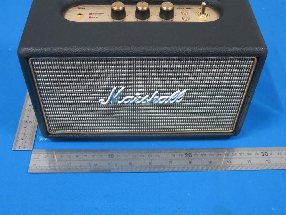
Click to zoom
Application Details
- Equipment Class
- DTS - Digital Transmission System
- Date of Grant
- Sep 30, 2014
- Application Purpose
- Original Equipment
- Date of Application
- Sep 29, 2014
- Equipment Note
- ACTIVE STEREO LOUDSPEAKER
- Frequency Range
- 2402.00000000 - 2480.00000000
- Country
- Sweden
Documents & Files
Document Text
Text extracted from the exhibit documents filed with the FCC. Open a document above to read the original.
Users Manual
ACTON - ACTIVE STEREO LOUDSPEAKER 001. SAFETY INSTRUCTIONS 002. COMPLIANCE MARKS 003. LANGUAGE INDEX 005. THE ACTON 006. BOX CONTENTS 008. GENERAL DESCRIPTION 010. TURNING THE POWER ON/OFF 012. USING THE ACTON WITH YOUR DEVICES 013. CHOOSING YOUR SOURCE 014. BLUETOOTH CONNECTION 018. CABLE CONNECTION 020. STANDBY MODES 022. ADJUSTING SOUND 023. TECHNICAL INFORMATION 024. TROUBLE SHOOTING 225. WARRANTY INFO USER MANUAL WWW.MARSHALLHEADPHONES.COM If you believe your product is defective or needs servicing or repair within the warranty period, please refer to the instructions on http://www.marshallheadphones.com/support/warranty/ warranty-hifi-speakers. For any questions or concerns contact: [email protected] Or join us on: facebook.com/marshallheadphones twitter.com/marshallhp Marshall Headphones C/O Zound Industries International AB, Box 6063, 10231 Stockholm Sweden * *PLEASE NOTE: Zound Industries does not accept products shipped to our address. Marshall is a trademark of Marshall Amplification Plc. Permission granted. Design of product and packaging are protected intellectual properties of Marshall Amplification Plc and Zound Industries Int. Ab. © 2014 Zound Industries. All rights reserved. Designed in Stockholm. Produced in China. IMPORTANT SAFETY INSTRUCTIONS IMPORTANT SAFETY INSTRUCTIONS • Read these instructions – All the safety and operating instructions should be read before this product is operated. • Keep these instructions – The safety and operating instructions should be retained for future reference. • Heed all warnings – All warnings on the appliance and in the operating instructions should be adhered to. • Follow all instructions – All operating and use instructions should be followed. WARNING! • WARNING – To reduce the risk of fire or electric shock, do not expose this apparatus to rain or moisture. The apparatus shall not be exposed to dripping or splashing and that objects filled with liquids, such as vases, shall not be placed on apparatus. • WARNING – do not cover. • WARNING – only use attachments/accessories specified by the manufacturer (such as the exclusive supply adapter, battery etc). • WARNING – the plug is the main disconnect device and should be used as such. The disconnect device should remain readily accessible. • WARNING – this active loudspeaker may emit high sound pressure levels. • WARNING – do not listen too close to the active loudspeaker. • WARNING – do not listen for an extended period of time at a high sound pressure level. • WARNING – do not attempt to remove the active loudspeaker chassis, there are no user serviceable parts. • WARNING – do not plug a guitar into the WOBURN. • WARNING – do not insert body parts or objects into the bass port for risk of injury. • DANGER – of dropping the product. • DANGER – of sharp corners. MOISTURE AND HUMIDITY • The active loudspeaker should be located in a place free from moisture and water. • Do not use this apparatus near water. Do not expose it to rain or dripping water. Do not splash water on it. INSTALLATION • Do not install near any heat sources such as radiators, heat registers, stoves, or other apparatus (including amplifiers) that produce heat. • No naked flame sources, such as lighted candles, should be placed on the active loudspeaker. • Do not block any ventilation openings. Install in accordance with the manufacturer’s instructions. • Use only with the cart, stand, tripod, bracket, or table specified by the manufacturer, or sold with the apparatus. When a cart is used, use caution when moving the cart/appartus combination to avoid injury from tip-over. CONNECTION • Connect the active loudspeaker according to the instructions in the manual. • Connect the active loudspeaker only to the correct mains voltage as shown on the equipment. • Protect the power cord from being walked on or pinched particularly at plugs, convenience recepta- cles, and the point where they exit the apparatus. • Use only power cables of the type specified in the operating instructions or as marked on the active loudspeaker. Do not substitute the separate power cable included with this active loudspeaker with any other power supply – use only the power cable provided by the manufacturer. • Do not defeat the safety purpose of the polarized or grounding-type plug. A polarized plug has two blades with one wider than the other. A grounding plug has two blades and a third grounding prong. The wide blade or the third prong are provided for your safety. If the provided plug does not fit into your outlet, consult an electrician for replacement of the obsolete outlet. • Unplug this apparatus during lightning storms or when unused for long periods of time. • Do not install in an area that impedes access to the power plug. Disconnecting the power plug is the only way to completely remove power to the product and the plug must be readily accessible at all times. CLEANING • Clean only with dry cloth. MAINTENANCE • Refer all servicing to qualified service personnel. Servicing is required when the apparatus has been damaged in any way, such as power-supply cord or plug is damaged, liquid has been spilled or objects have fallen into the apparatus, the apparatus has been exposed to rain or moisture, does not operate normally, or has been dropped. • CAUTION: These servicing instructions are for use by qualified service personnel only. To reduce the risk of electric shock, do not perform any servicing unless you are qualified to do so. 002. COMPLIANCE MARKS CAUTION: To prevent the risk of electric shock, do not remove cover (or back plate). There are no user serviceable parts inside. Refer servicing to qualified service personnel. This appliance may not be treated as regular household waste. Management of WEEE (Waste Electrical and Electronic Equipment) is applica- ble in member states of the European Union and other European countries with individual national policies on the management of WEEE. If you need more information on the col…
Text truncated - open the document above for the full version.
Cover Letter(s)
SCS-F18: Project and Product Certification Representative Authorization Letter Page 1 of 2 Rev 5.0 775 Montague Expressway Milpitas, CA 95035 Tel: 408-526-1188 Fax: 408-526-1088 Email: [email protected] Project and Product Certification Representative Authorization Letter Reason for Amendment (current / obsolete) Revision History Approved Date From To Initial Release (obsolete) 1.0 1.0 Nov-14-2006 Revised wording (obsolete) 1.0 2.0 Sept–25-2007 Updated company template (obsolete) 2.0 3.0 Jan-31-2012 Updated letter information (obsolete) 3.0 4.0 May-23-2014 Added FCC ID field (current) 4.0 5.0 Sept 16 2014 SCS-F18: Project and Product Certification Representative Authorization Letter Page 2 of 2 Rev 5.0 Zound Industries (2014-09-25) To: SIEMIC, INC. 775 Montague Expressway, Milpitas, CA 95035 USA Dear Sir/Madam, Re: Product Certification Representative Authorization Letter We, _____ Zound Industries_____hereby authorize SIEMIC, Inc. to act as a Certification Body for certifying for the following project(s): Product description: ACTIVE STEREO LOUDSPEAKER Model Number: ACTON FCC ID: 2AAGF-ACTON Sincerely, Nils Noren Technical Manager Torsgatan 2 111 23 Stockholm Sweden
Cover Letter(s)
SCS-F19: Confidentiality Request Letter Page 1 of 2 Rev 3.0 775 Montague Expressway Milpitas, CA 95035 Tel: 408-526-1188 Fax: 408-526-1088 Email: [email protected] Confidentiality Request Letter Reason for Amendment (current / obsolete) Revision History Approved Date From To Initial Release (obsolete) 1.0 1.0 Nov-14-2006 Adding CFR 2.459 (obsolete) 1.0 2.0 August – 11 - 2008 Updated company template & Added text box (current) 2.0 3.0 Jan-31-2012 SCS-F19: Confidentiality Request Letter Page 2 of 2 Rev 3.0 Zound Industries (2014-09-25) To: Federal Communications Commission Authorization and Evaluation Division 7435 Oakland Mills Road Columbia, MD Subject: Permanent Confidentiality Request for FCC ID: 2AAGF-ACTON We hereby request confidential treatment of information accompanying this application as outlined below: - Block Diagram - Schematics - Operational Description The above materials contain trade secrets and proprietary information not customarily released to the public. The public disclosure of these materials may be harmful to the applicant and provide unjustified benefits to its competitors. The applicant understands that pursuant to Section 0.457 & 0.459 of the Rules, disclosure of this application and all accompanying documentation will not be made before the date of the Grant for this application. Sincerely, Nils Noren Technical Manager Torsgatan 2 111 23 Stockholm Sweden
ID Label/Location Info
Label Location on EUT
Internal Photos
Antenna
RF Exposure Info
RF EXPOSURE EVALUATION According to FCC 1.1310: The criteria listed in the following table shall be used to evaluate the environment impact of human exposure to radio frequency(RF) Radiation as specified in §1.1307(b) FCC ID:2AAGF-ACTON EUT Specification EUT ACTIVE STEREO LOUDSPEAKER Frequency band (Operating) WLAN: 2.412GHz ~ 2.462GHz WLAN: 5.18GHz ~ 5.32GHz / 5.50GHz ~ 5.70GHz WLAN: 5.745GHz ~ 5825GHz Others Device category Portable (<20cm separation) Mobile (>20cm separation) Others ___ Exposure classification Occupational/Controlled exposure (S = 5mW/cm2) General Population/Uncontrolled exposure (S=1mW/cm2) Antenna diversity Single antenna Multiple antennas Tx diversity Rx diversity Tx/Rx diversity Max. output power 2.44dBm(0.001754W) Antenna gain (Max) 0 dBi Evaluation applied MPE Evaluation SAR Evaluation Limits for Maximum Permissible Exposure(MPE) Frequency Range(MHz) Electric Field Strength(V/m) Magnetic Field Strength(A/m) Power Density(mW/cm 2 ) Average Time (A) Limits for Occupational/Control Exposures 300-1500 -- -- F/300 6 1500-100000 -- -- 5 6 (B) Limits for General Population/Uncontrol Exposures 300-1500 -- -- F/1500 6 1500-100000 -- -- 1 30 Friis transmission formula: Pd=(Pout*G)\(4*pi*R2) Where Pd= Power density in mW/cm 2 Pout=output power to antenna in Mw G= gain of antenna in linear scale Pi=3.1416 R= distance between observation point and center of the radiator in cm Pd the limit of MPE, 1mW/cm2. If we know the maximum gain of the antenna and total power input to the antenna, through the calculation, we will know the distance where the MPE limit is reached. Measurement Result Channel Frequency (MHz) Output Peak power (mW) Output Peak power (dBm) Antenna Gain (dBi) Antenna Gain (numeric) Power density at 20cm (mW/ cm2 ) Power density Limits (mW/cm 2 ) 2402 1.122 0.50 0 1 0.0002232 1 2442 1.435 1.57 0 1 0.0002855 1 2480 1.754 2.44 0 1 0.0003489 1 Signature Nils Noren Technical Manager Torsgatan 2 111 23 Stockholm Sweden
Test Report
TRF No. FCC Part 15.247/A Page 1 of 48 Report No. KAD140731134E Ver.1.0 ELECTROMAGNETIC EMISSIONS COMPLIANCE REPORT INTENTIONAL RADIATOR CERTIFICATION TO FCC PART 15 SUBPART C REQUIREMENT OF ACTIVE STEREO LOUDSPEAKER Model No.: ACTON Trade Mark: FCC ID: 2AAGF-ACTON Report No.: KAD140731134E Issue Date: September 25, 2014 Prepared for Zound Industries Torsgatan 2 111 23 Stockholm Sweden Prepared by DONGGUAN EMTEK CO., LTD. No.281, Guantai Road, Nancheng District, Dongguan, Guangdong, China TEL: 86-769-22807078 FAX: 86-769-22807079 This report shall not be reproduced, except in full, without the written approval of DONGGUAN EMTEK CO., LTD. TRF No. FCC Part 15.247/A Page 2 of 48 Report No. KAD140731134E Ver.1.0 VERIFICATION OF COMPLIANCE Applicant: Zound Industries Torsgatan 2 111 23 Stockholm Sweden Manufacturer: DONGUAN TRISTAR ELECTRONIC CO., LTD. NO.24A DongXing AVE South, ZhenXingWei, TangXia Town, DongGuan City, China Product Description: ACTIVE STEREO LOUDSPEAKER Trade Mark: Model Number: ACTON File Number: KAD140731134E Date of Test: July 31, 2014 to September 13, 2014 We hereby certify that: The above equipment was tested by DONGGUAN EMTEK CO., LTD. The test data, data evaluation, test procedures, and equipment configurations shown in this report were made in accordance with the procedures given in ANSI C63.4 (2009) and the energy emitted by the sample EUT tested as described in this report is in compliance with conducted and radiated emission limits of FCC Rules Part 15.247(2013). The test results of this report relate only to the tested sample identified in this report. Approved By Sam.Lv / Q.A. Manager DONGGUAN EMTEK CO., LTD. TRF No. FCC Part 15.247/A Page 3 of 48 Report No. KAD140731134E Ver.1.0 Modified Information Version Summary Revision Date Report No. Ver.1.0 Original Report / KAD140731134E TRF No. FCC Part 15.247/A Page 4 of 48 Report No. KAD140731134E Ver.1.0 Table of Contents 1. GENERAL INFORMATION ............................................................................................................ 6 1.1 PRODUCT DESCRIPTION ................................................................................................................... 6 1.2 TEST METHODOLOGY ....................................................................................................................... 7 1.3 SPECIAL ACCESSORIES .................................................................................................................... 7 1.4 EQUIPMENT MODIFICATIONS ............................................................................................................ 7 1.5 TEST FACILITY ................................................................................................................................. 7 2. SYSTEM TEST CONFIGURATION............................................................................................... 8 2.1 EUT CONFIGURATION ...................................................................................................................... 8 2.2 EUT EXERCISE ................................................................................................................................ 8 2.3 TEST PROCEDURE ........................................................................................................................... 8 2.4 CONFIGURATION OF TESTED SYSTEM .............................................................................................. 9 3. DESCRIPTION OF TEST MODES .............................................................................................. 10 4. CONDUCTED EMISSIONS TEST ............................................................................................... 11 4.1 MEASUREMENT PROCEDURE: ........................................................................................................ 11 4.2 TEST SET-UP (BLOCK DIAGRAM OF CONFIGURATION) ................................................................... 11 4.3 MEASUREMENT EQUIPMENT USED: ................................................................................................ 11 4.4 CONDUCTED EMISSION LIMIT ......................................................................................................... 12 4.5 MEASUREMENT RESULT: ................................................................................................................ 12 4.6 CONDUCTED MEASUREMENT PHOTOS: .......................................................................................... 15 5. RADIATED EMISSION TEST ...................................................................................................... 16 5.1 MEASUREMENT PROCEDURE ......................................................................................................... 16 5.2 TEST SET-UP (BLOCK DIAGRAM OF CONFIGURATION) ................................................................... 17 5.3 MEASUREMENT EQUIPMENT USED: ................................................................................................ 18 5.4 RADIATED EMISSION LIMIT .............................................................................................................. 18 5.5 MEASUREMENT RESULT ................................................................................................................. 19 5.6 RADIATED MEASUREMENT PHOTOS: .............................................................................................. 29 6. 6DB BANDWIDTH MEASUREMENT ......................................................................................... 30 6.1 MEASUREMENT PROCEDURE ......................................................................................................... 30 6.2 TEST SET-UP (BLOCK DIAGRAM OF CONFIGURATION) ................................................................... 30 6.3 MEASUREMENT EQUIPMENT USED: ................................................................................................ 30 6.4 MEASUREMENT RESULTS: ..............…
Text truncated - open the document above for the full version.
Contact Information
Applicant
Edison Xu(Compliance Engineer)
Test Firm
EMTEK (DONGGUAN) CO.,LTDSam Lv
Technical Specifications
| # | Rule Parts | Frequency Range | Power Output |
|---|---|---|---|
| 1 | 15C | 2.40 GHz - 2.48 GHz | 1.75 mW |
Other Applications from Zound Industries International AB
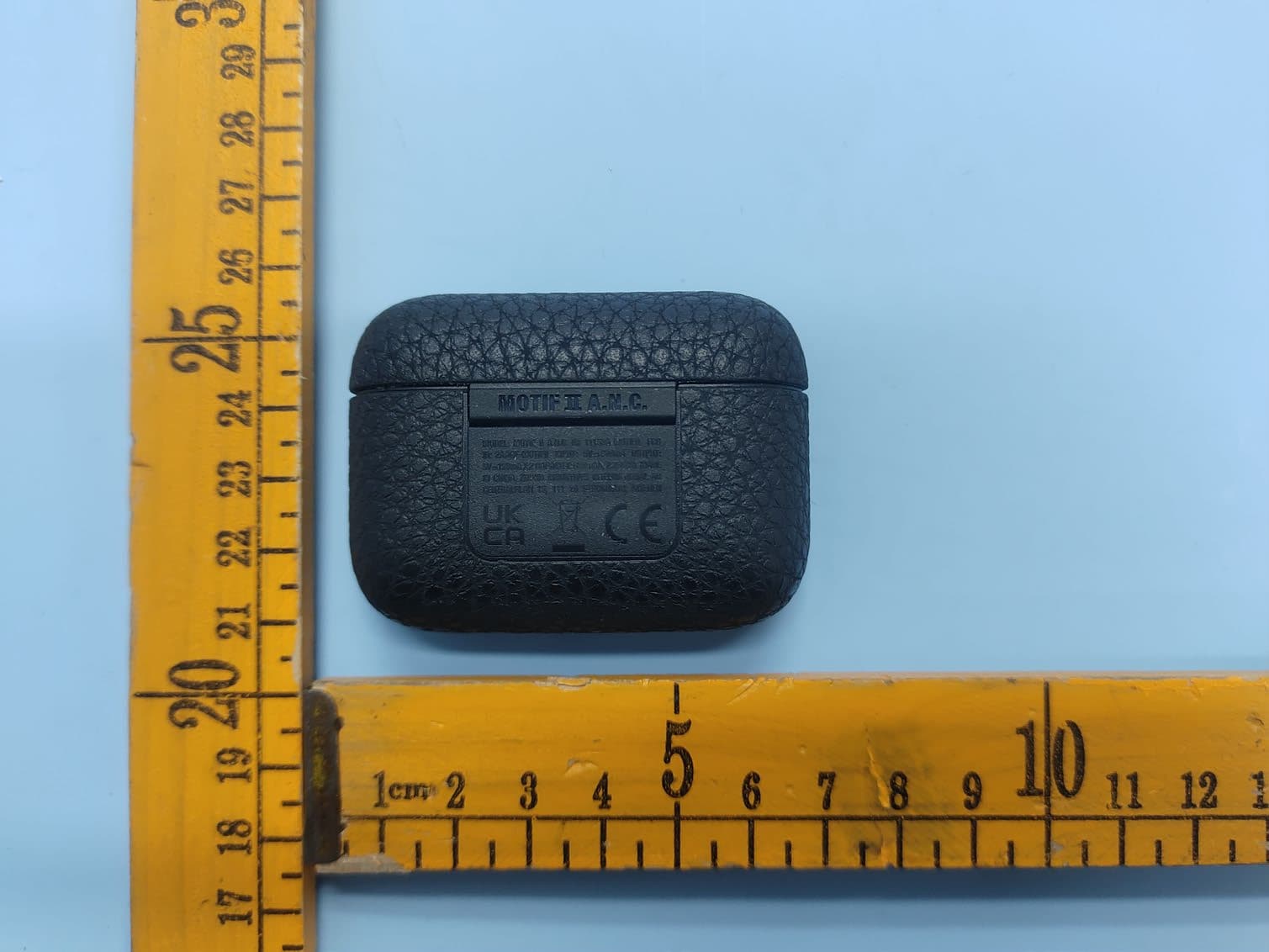
2AAGF-MOTIFII
Jul 23, 2023True Wireless Headphones
Equipment Class
DTS - Digital Transmission System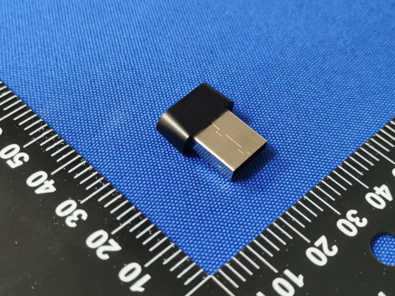
2AAGF-ZONGLE
May 16, 2023Audio Transmitter
Equipment Class
DTS - Digital Transmission System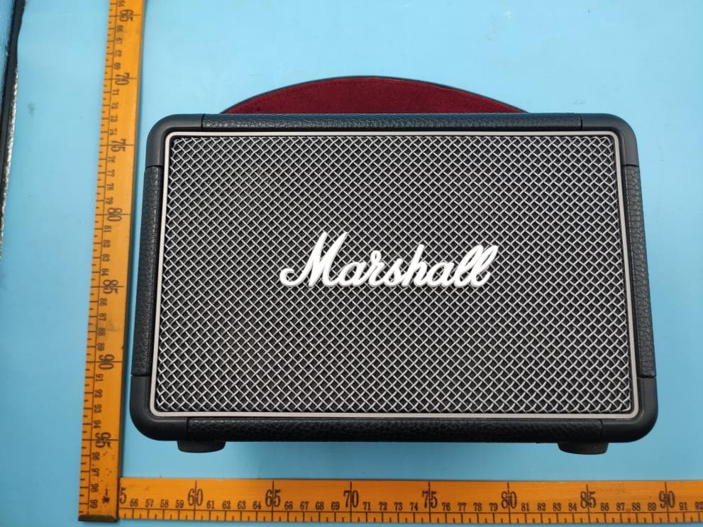
2AAGF-KILBURNIIB
Jul 14, 2022PORTABLE STEREO LOUDSPEAKER
Equipment Class
DSS - Part 15 Spread Spectrum Transmitter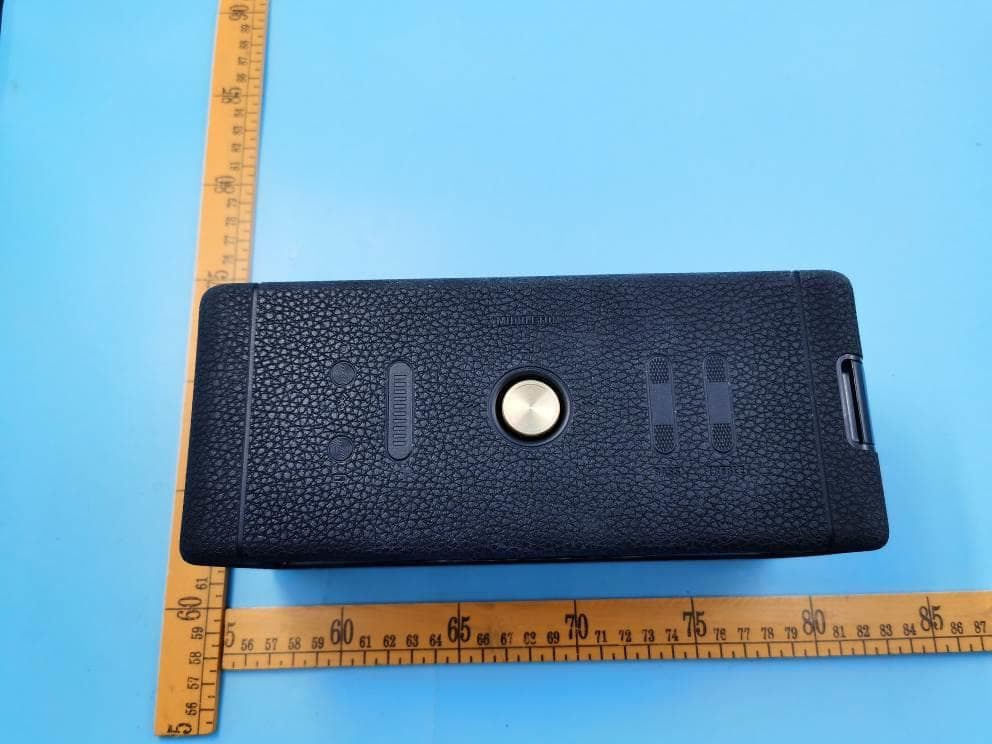
2AAGF-MIDTON
Jun 08, 2022PORTABLE LOUDSPEAKER
Equipment Class
DSS - Part 15 Spread Spectrum Transmitter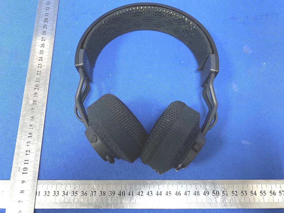
2AAGF-RPT02
Apr 10, 2022HEADPHONES
Equipment Class
DSS - Part 15 Spread Spectrum Transmitter