FCCID.CO- FCC ID Database
HomeCompaniesEquipment ClassesSearch

© 2026 FCC ID Database. All rights reserved.

AboutContactData sourced from FCC public records
  1. Home/
  2. Audiovox Incaar Systems GmbH/
  3. 2AAKLD189070

2AAKLD189070Rear Seat Entertainment System - BCU

Audiovox Incaar Systems GmbH
Rear Seat Entertainment System - BCU - FCC ID 2AAKLD189070 - Audiovox Incaar Systems GmbH
Click to zoom

Application Details

Equipment Class
DTS - Digital Transmission System
Date of Grant
Apr 21, 2014
Application Purpose
Original Equipment
Date of Application
Apr 21, 2014
Equipment Note
Rear Seat Entertainment System - BCU
Frequency Range
2412.00000000 - 2462.00000000
Company
Audiovox Incaar Systems GmbH
Country
United Kingdom

Documents & Files

Select a file to view
Users Manual

↗
↗
↗

Attestation Statements

↗

Cover Letter(s)

↗
↗
↗

External Photos

↗

ID Label/Location Info

↗

Internal Photos

↗

RF Exposure Info

↗

Test Report

↗

Test Setup Photos

↗

Document Text

Text extracted from the exhibit documents filed with the FCC. Open a document above to read the original.

Users Manual

TSD B08001 1 RSE – OverviewThe Rear Seat Entertainment system (RSE) allows passengers inthe rear compartment to access multimedia content and basicInfotainment functions using the Touch Screen Remote (TSR) ora suitable device running the Bentley Flying Spur RSE app.Dependent upon specification, the RSE system may consist of the following items:• Display screens > • Multimedia interface > • Media loaders > • Left and right headphone sockets > • Wireless headphones > Fig. 1 RSE features (5 seat vehicle shown) 1 Display screen > 2 Media loader > 3 Touch screen remote (TSR) > 4 Headphone connections > Multimedia interfaceMedia loadersTouch screen remote (TSR)Using the RSESettingsHeadphones 1 2 1 3 2 4 B0918 2 TSD B08001 Multimedia interfaceFig. 2 Multimedia interface 1 RSE SIM card reader2 Multimedia interfaceThe multimedia interface (located in the glovebox), contains thefollowing:• Jukebox - 64GB memory capacity for storing media files. • Multimedia interface - Enables connection of a compatiblemedia device to the Infotainment system. • RSE SIM card reader - Enables access to the internet when a suitable SIM card is present. The SIM card should be inserted into the card slot with the ‘chip’ facing upwards and the ‘cut-off ’ corner pointing towards theright. Note • Very high or very low temperatures (a common occurrence in a car's interior) can cause damage to a portable player and/or impair itsperformance. Please do not leave your portable player in the car incase of extreme temperatures. • Handle the adapter cable with care. Make sure the cable does not become pinched or trapped. Media loadersTouch screen remote (TSR)Using the RSESettingsHeadphones B0922.LH 1 2 TSD B08001 3 Media loadersRaise the front of the cover to access the features of the medialoader.Fig. 3 Seatback features 1Display screen > 2 CD/DVD disc slot > 3 CD/DVD Eject button > 4 SD memory card slot > 5HDMI input > 6 USB connector > Multimedia interfaceTouch screen remote (TSR)Using the RSESettings Headphones B0920 1 USB HDMI SD 2 3 4 5 6 4 TSD B08001 Touch screen remote (TSR)When controlling the RSE system, the TSR works like a track pad,where the movement of a finger on the central area of the TSRtouch screen is used to highlight an option on the display screen.The highlighted option can then be selected by tapping the screen. It is possible to scroll through lists by ‘swiping’ a finger on thetouch screen in the direction desired. To quickly scroll through alist, hold a finger on the edge of the touch screen at the end ofthe swipe gesture. The scrolling action will stop when the end ofthe list is reached or when the finger is removed from the screen.For general information on usin g the TSR, refer to the ‘Touch screen remote’ heading in the Infotainment chapter of the Owner’sHandbook.Fig. 4 TSR in gesture mode (left-hand RSE system selected) 1 On/off function button > 2 Touch screen3 Select right-hand RSE system function button > 4 RSE main menu function button > Multimedia interfaceMedia loadersUsing the RSESettingsHeadphones B0935.EN 1 2 3 4 Menu TSD B08001 5 TSR function buttonsDependent upon the currently selected menu, the followingfunction buttons may appear on the TSR or the RSE display screen: - Press to turn the currently selected RSE system on or off.- Press to return to the previous menu screen.- Press to return to the RSE system main menu. - Displays the currently playing media. Switching the RSE system on and offSwitching between RSE screensAdjusting the volume Switching the RSE system on and offTo switch on the RSE system using the TSR, select the RSE app from the app selector screen.The TSR will prompt the user to select from the following options: - Left-hand RSE system and display monitor on.- Right-hand RSE system and display monitor on.- Both RSE systems and display monitors on. When both sides of the RSE system are switched on together, theTSR control will default to the left-hand RSE system.TSR function buttonsSwitching between RSE screensAdjusting the volume Menu 6 TSD B08001 Switching between RSE screensTo switch off the RSE system, proceed as follows:1. Use the or function button to select the desired side of the RSE system. 2. Press the function button. A pop-up window displaying the following options will open (the left-hand RSE system has beenselected for this example): Switch off left display or Switch on left display - Switches on or off the left-hand display only. When the display is switched off, the audio for the currently playing media willcontinue to be output through the currently selected source.Switch off left system - Switches off the left-hand RSE system.Cancel - Closes the pop-up window and returns to the previous TSR screen. 3. Select the desired option.To switch on the RSE system after it has been switched off via theTSR, or if only one side had been switched on at initial start-up,press the function button. TSR function buttonsSwitching the RSE system on and offAdjusting the volume Adjusting the volumeFig. 5 Volume controls 1 Left-hand RSE volume controls2 Infotainment system volume controls3 Right-hand RSE volume controls4 Volume control buttonPressing the volume control button (4) opens the volume controlpop-up window. It is possible to control the volume settings for the Infotainmentsystem or any wired or wireless headphones that may beconnected to the RSE system. Press the or function buttons for the desired device to increase or decrease the volumeof the desired output.Press the function button to mute the desired output. B0934 1 2 3 4 TSD B08001 7 If wired and wireless headphones are connected to the same sideof the RSE system, it is possible to toggle between adjustment foreach pair of headphones by pressing the or function button at the top of the pop-up window. Note The volume control pop-up window will close after approximately5 seconds of inactivity.TSR function buttonsSwitching the RSE system on and offSwitching between RSE screens Using the RSEFig. 6 Main menu There …

Text truncated - open the document above for the full version.

Users Manual

xx Important information Important informationRunning-in proceduresDetailed information regarding the running-in procedures for thecar can be found under the heading ‘Running-in procedures’ onpage 65.FuelThis handbook refers to cars fitted with catalytic converters in theexhaust system. This car can be run on either unleaded fuel or bioethanol E85, orany mixture ratio of these two fuels.For further information, refer to the heading ‘Fuel specification’on page 133. Occupant restraintsThis car is equipped with driver and passenger air bagsupplementary restraint systems, thorax protection on the outerp o r t i o n o f ea c h se a t b a ck res t a n d s i d e h e a d p ro t e c t i o n w i t h i n e a c hside of the upper trim panels. For maximum safety in all types of accidents, or if the car is stoppedsuddenly, the driver and all passe ngers should, at all times, be restrained by the safety belts provided. Air bag protection doesnot reduce the necessity to wear a safety belt. For the sake of the environment Undeployed air bag modules and pre-tensioners are classified asPerchlorate Material – Special handling may apply. Seewww.dtsc.ca.gov/hazardouswaste/perchlorate. When the vehicle or parts of the restraint system including air bag modules safety belts withpre-tensioners are scrapped, all applicable laws and regulations mustbe observed. Your authorised Bentley dealer is familiar with theserequirements and we recommend that you have your Dealer perform this service for you. ServiceThe importance of regular servicing on a time expired or mileagebasis cannot be over-emphasised. The driver information panel displays a reminder when the car isdue for service. However, it is the responsibility of the owner toensure that the car is maintained in accordance with the specifiedservice schedules. It is strongly recommended that all maintenanceand repair work is carried out by an authorised Bentley dealer. Work carried out under the terms of the Warranty given witheach new car must be performed by an authorised Bentley dealer. The Bentley insignia is displayed by authorised Bentley dealers whowill have factory trained personnel, up-to-date technicalinformation, specialist tools, and approved parts. Similarly, shouldcoachwork or paintwork repairs be required, the use of anauthorised Bentley dealer is recommended. Work arranged andundertaken at these establishments will be carried out usingapproved procedures and materials. WarrantyDetailed information on warranties applicable to cars conformingto certain market specifications can be found in the ServiceHandbook. Unt i t l ed1. f m Page xx Tuesday, N ovem ber 12, 2013 4: 08 PM Important information xxi Symbols used within this bookTo ensure the optimum safety of the occupants and the operationalsafety and reliability of the car, you are advised to pay particularattention to the information accompanying the warning symbols. The following symbols are used throughout this handbook: Caution Identifies information which prevents the car being damaged. Important Identifies information which will either, quickly improve theunderstanding of a feature, or informs the user to follow an instruction. For the sake of the environment Identifies information relating to the protection of the environment. Note Identifies additional information of a more general nature.Warning boxes WARNING Throughout these documents, any information regardingwarnings will be contained inside a box. These warnings containimportant information on safety and how to reduce the risk ofpersonal injury and death. The warning boxes will contain a symbol. An arrow in thebottom right-hand corner denotes there is more information inthe warning, either in the next column or on the next page.A square in the bottom right-hand corner denotes the end ofthe warning. Unt i t l ed1. f m Page xxi Tuesday, N ovem ber 12, 2013 4: 08 PM xxii Statements of compliance Trunk entrapment Interior release handle(emergency use only) California Proposition 65 warningStatements of complianceSecurity systemSiemens AG states that this device complies with part 15 of theFCC Rules. Operation is subject to the following two conditions.1. This device may not cause harmful interference, and 2. This device must accept any interference received, including interference that may cause undesired operation. This digital apparatus does not exceed the Class A limits for radionoise emission from digital apparatus set out in the RadioInterference Regulations of Industry Canada. WARNING Never leave the car unattended especially with the trunk lid leftopen. A child could crawl into the trunk and pull the trunk lidclosed, becoming trapped and unable to get out. To reduce therisk of personal injury, always keep the trunk lid as well as thecar doors closed when not in use. In the event of accidental trunk entrapment, a release handle isfitted to the underside of the trunk lid. Ensure the handle remainsunobstructed at all times.The handle is visible from inside the trunk for up to thirty minutesafter the trunk lid is closed, to assist with exiting the car in theevent of accidental entrapment. Should accidental entrapment occur, press the handle downtowards the bumper, then push upward to open the trunk lid. WA RNI NG Engine Exhaust, some of its constituents, and certain carcomponents contain or emit chemicals known to the State ofCalifornia to cause cancer and birth defects and reproductiveharm. In addition, certain fluids contained in cars and certain productsof component wear contain or emit chemicals known to the Stateof California to cause cancer and birth defects or otherreproductive harm.Battery posts, terminals and related accessories contain lead andlead components, chemicals known to the State of California tocause cancer and reproductive harm. Wash hands after handling. WA RNI NG Any changes or modifications to any of the listed devices notexpressly approved by the party responsible for compliance couldvoid the user’s authority to…

Text truncated - open the document above for the full version.

Users Manual

Bentley RSE Control Unit Installation Guide Installation for J829 (aftersales reference)  1 Control unit 2 for information electronics (J829) - To remove and fit General Information The Control unit 2 for information electronics -J829- -arrowed- is located inside the glove box on the outboard side. Note Image shows a right hand drive vehicle. Left hand drive vehicle is a mirror image. Replacement control units require additional programming via the Vehicle tester. Refer to Installation instructions. Special tools and workshop equipment required  Removal tool -WT 10221- 2  Vehicle tester Torque tightening values Unless otherwise shown, standard torque values apply. → Rep.-Gr.00 Removal The following procedure is based on a right hand drive vehicle. The procedure is the same for both left hand and right hand drive. – Switch off the ignition. – Insert the removal tools -WT 10221- into the slots in the control unit until they locate. Note Ensure that both tools click into position before attempting to remove the control unit. – Push and hold the tools outwards in the direction of the -arrows- to release the retaining clips, then pull rearwards evenly to slide out the control unit. 3 – Press the retaining clips -arrowed- inwards on both sides to release the removal tools -1-. – Disconnect the harness connectors -1- and remove the control unit -2- from the vehicle. Installation Installation is the reverse of removal procedure, noting the following. – Ensure all electrical connectors are connected correctly prior to installation. – After installation ensure the catches secure the control unit on both sides. This can be confirmed by an audible click being heard and then attempting to withdraw the control unit without using the removal tools. – A new control unit will require coding. Connect the Vehicle tester to the vehicle and run Software Version Management (SVM). Refer to "Diagnostic system - Guided functions/Component replacement". → Rep.-Gr.97 4 CAUTION: FCC REGULATORY REQUIREMENTS This device complies with Part 15 of the FCC Rules. Operation is subject to the following two conditions: 1 - This device may not cause harmful interference, and 2 - This device must accept any interference received, including interference that may cause undesired operation. Any change or modification to the product not expressly approved by the manufacturer could void the user's authority to operate the device. FCC RF Radiation Exposure Statement: This equipment contains a radio transmitter. It is designed and manufactured not to exceed the emission limits for exposure to radio frequency energy set by the Federal Communication Commission (FCC) of the US Government in accordance with part 2.1091 of the FCC Rules for an uncontrolled environment. The equipment is installed to ensure a minimum 20 cm distance between the two antennas and, with a minimum safe operating distance of 20 cm between the respective antennas and the car occupants 5 CAUTION: IC REGULATORY REQUIREMENTS This device complies with Industry Canada licence-exempt RSS standard(s). Operation is subject to the following two conditions: 1 - This device may not cause interference. 2 - This device must accept any interference, including interference that may cause undesired operation of the device. Any change or modification to the product not expressly approved by the manufacturer could void the user's authority to operate the device. IC RF Radiation Exposure Statement: This equipment contains a radio transmitter. It is designed and manufactured not to exceed the emission limits for exposure to radio frequency energy as stated within the Industry Canada RSS standard(s). This radio transmitter (IC: 11196A- D189070) has been approved by Industry Canada to operate with the antenna types listed below with the maximum permissible gain and required antenna impedance for each antenna type indicated. Antenna types not included in this list, having a gain greater than the maximum gain indicated for that type, are strictly prohibited for use with this device. Antenna Models: For GSM / UMTS: Smarteq Antenna AB; part No: 3W7.035.524.A For Bluetooth / WLAN: WISI 6 Automotive GmbH & Co. KG; part: Wisi AG91 WLAN Bentley 4W0.962.131 The equipment is installed to ensure a minimum 20 cm distance between the two antennas and, with a minimum safe operating distance of 20 cm between the respective antennas and the car occupants. ATTENTION: IC EXIGENCES RÉGLEMENTAIRES Cet appareil est conforme avec Industrie Canada RSS exemptes de licence standard (s). Son fonctionnement est soumis aux deux conditions suivantes: 1 - Ce dispositif ne peut causer des interférences. 2 - Ce dispositif ne peut causer des interférences. Tout changement ou modification au produit non expressément approuvés par le fabricant peuvent annuler le droit de l'utilisateur à utiliser l'appareil. IC Rayonnement RF de Déclaration d'exposition: Cet appareil contient un émetteur radio. Il est conçu et fabriqué pour ne pas dépasser les limites d'émission pour l'exposition à l'énergie de radiofréquence comme indiqué dans la norme (s) d'Industrie Canada RSS Le présent émetteur radio (IC: 11196A-D189070) a été approuvé par Industrie Canada pour fonctionner avec les types d'antenne énumérés ci- dessous et ayant un gain admissible maximal et l'impédance requise pour chaque type d'antenne. Les types 7 d'antenne non inclus dans cette liste, ou dont le gain est supérieur au gain maximal indiqué, sont strictement interdits pour l'exploitation de l'émetteur. Modèles d'antenne: Pour GSM / UMTS: Smarteq Antenna AB; part No: 3W7.035.524.A Pour Bluetooth / WLAN: WISI Automotive GmbH & Co. KG; part: Wisi AG91 WLAN Bentley 4W0.962.131 L'équipement est installé pour assurer une distance minimale de 20 cm entre les deux antennes et, avec une distance de fonctionnement minimale de sécurité de 20 cm entre les antennes respectives et les occupants de la voiture.

Attestation Statements

Audiovox Incaar Systems GmbH Branch Office: 14 Boundary Business Centre, Boundary Way, Woking, Surrey, GU21 5DH United Kingdom Tel: +44 (0)1483 722 531 Fax: +44 (0)1483 740 204 Vat Number: GB915196124  Company Registration Number: FC027852  Branch Number: BR009601 Head Office: Lise-Meitner-Strasse 9, 50259 Pulheim, Germany Tel: +49 (0) 2234 807 0 Fax: +49 (0) 2234 807 399 UST (VAT) - ID: DE255639566  HRB 611693 (Trade Register) applied for Köln (Cologne) Bankverbindung (Bankaccount)  Commerzbank Köln  Konto (Account) 133 00 26  BLZ (BIC) 370 400 44  Geschäftsführer (Directors): Ciaran Mitchell, Mark Finger, John Verbinnen  Date: 29.10.2013 Telecommunication Certification Body UL VS Ltd. Pavilion A Ashwood Park Basingstoke Hampshire RG23 8BG United Kingdom Subject: Relationship between Audiovox Incaar Systems GmbH & Bentley Motors Ltd FCC ID: 2AAKLD189070 and 2AAKLD189050 To whom it may concern We, Audiovox Incaar Systems GmbH, hereby attest that we contracted by Bentley Motors Ltd for the development, manufacturing and supply of FCC ID: 2AAKLD189070 and FCC ID: 2AAKLD189050. As a result of the nature of the contract, exhibits for the certification of the Audiovox Incaar Systems GmbH devices FCC ID: 2AAKLD189070 and FCC ID: 2AAKLD189050 comprise of documentation supplied by both Audiovox Incaar Systems GmbH and Bentley Motors Ltd. Please contact the undersigned if there are any further questions or additional information needed in this matter Yours faithfully Damian Trybuszewski Development Manager

Cover Letter(s)

Audiovox Incaar Systems GmbH Branch Office: 14 Boundary Business Centre, Boundary Way, Woking, Surrey, GU21 5DH United Kingdom Tel: +44 (0)1483 722 531 Fax: +44 (0)1483 740 204 Vat Number: GB915196124  Company Registration Number: FC027852  Branch Number: BR009601 Head Office: Lise-Meitner-Strasse 9, 50259 Pulheim, Germany Tel: +49 (0) 2234 807 0 Fax: +49 (0) 2234 807 399 UST (VAT) - ID: DE255639566  HRB 611693 (Trade Register) applied for Köln (Cologne) Bankverbindung (Bankaccount)  Commerzbank Köln  Konto (Account) 133 00 26  BLZ (BIC) 370 400 44  Geschäftsführer (Directors): Ciaran Mitchell, Mark Finger, John Verbinnen  09.30.2013 Telecommunication Certification Body UL VS Ltd Pavilion A Ashwood Park Basingstoke Hampshire RG23 8BG United Kingdom Subject: Agency Letter To whom it may concern This is to certify that Audiovox Incaar Systems GmbH authorises UL VS Ltd to act on our behalf for the application of the BCU, FCC ID: 2AAKLD189070 to UL VS Ltd. Telecommunication Certification Body. We certify that we are not subject to a denial of Federal benefits, that include FCC benefits, pursuant to Section 5301 of the Anti-Drug Abuse Act of 1988, 21 U.S.C. § 862 because of a conviction for possession or distribution of a controlled substance. See 47 CFR 1.2002(b) for the definition of a "party" for these purposes. Yours sincerely Damian Trybuszewski Development Manager

Cover Letter(s)

Audiovox Incaar Systems GmbH Branch Office: 14 Boundary Business Centre, Boundary Way, Woking, Surrey, GU21 5DH United Kingdom Tel: +44 (0)1483 722 531 Fax: +44 (0)1483 740 204 Vat Number: GB915196124  Company Registration Number: FC027852  Branch Number: BR009601 Head Office: Lise-Meitner-Strasse 9, 50259 Pulheim, Germany Tel: +49 (0) 2234 807 0 Fax: +49 (0) 2234 807 399 UST (VAT) - ID: DE255639566  HRB 611693 (Trade Register) applied for Köln (Cologne) Bankverbindung (Bankaccount)  Commerzbank Köln  Konto (Account) 133 00 26  BLZ (BIC) 370 400 44  Geschäftsführer (Directors): Ciaran Mitchell, Mark Finger, John Verbinnen  Date: 09.30.2013 Telecommunication Certification Body UL VS Ltd. Pavilion A Ashwood Park Basingstoke Hampshire RG23 8BG United Kingdom Subject: Permanent Confidentiality Request; Certification Application FCC ID: 2AAKLD189070 Pursuant to Sections 0.457 and 0.459 of CFR 47, Company Audiovox Incaar Systems GmbH request that the following information, provided to support the FCC application for the Equipment BCU, FCC ID: 2AAKLD189070, be held permanently confidential:  Schematics  Block Diagrams  Parts List  Operational Description The above material contains trade secrets not customarily released to public that are judged to have the potential to cause detriment to the applicant and provide unjustified benefits to its competitors. This information should not be available for public disclosure for an indefinite period of time. Yours sincerely Damian Trybuszewski Development Manager

Cover Letter(s)

Audiovox Incaar Systems GmbH Branch Office: 14 Boundary Business Centre, Boundary Way, Woking, Surrey, GU21 5DH United Kingdom Tel: +44 (0)1483 722 531 Fax: +44 (0)1483 740 204 Vat Number: GB915196124  Company Registration Number: FC027852  Branch Number: BR009601 Head Office: Lise-Meitner-Strasse 9, 50259 Pulheim, Germany Tel: +49 (0) 2234 807 0 Fax: +49 (0) 2234 807 399 UST (VAT) - ID: DE255639566  HRB 611693 (Trade Register) applied for Köln (Cologne) Bankverbindung (Bankaccount)  Commerzbank Köln  Konto (Account) 133 00 26  BLZ (BIC) 370 400 44  Geschäftsführer (Directors): Ciaran Mitchell, Mark Finger, John Verbinnen  22.04.2013 UL VS Ltd. Pavilion A Ashwood Park Ashwood Way Basingstoke Hampshire RG23 8BG United Kingdom Subject: BCU schematic clarification of red crosses used in the schematic document for the device BCU Unit D189070 FCC IC Number: 2AAKLD189070 To whom it may concern Red crosses on the schematic exhibit indicate removed components and are not assembled on the product. Yours faithfully, Damian Trybuszewski Development Manager

External Photos

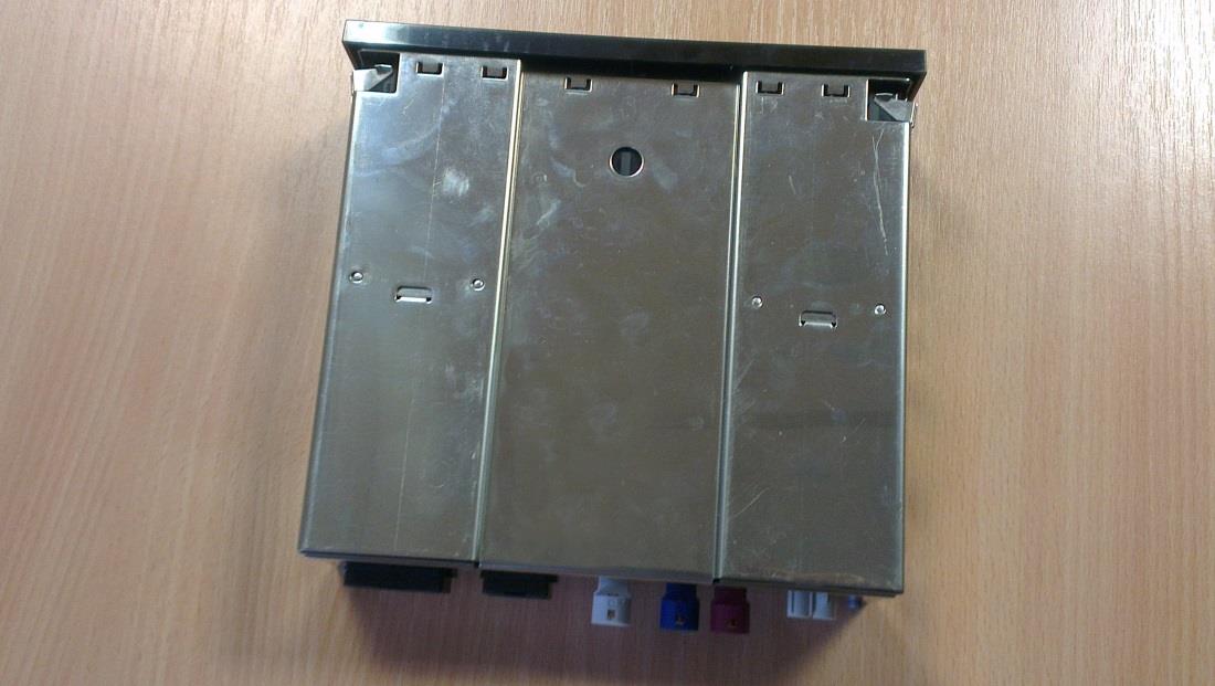
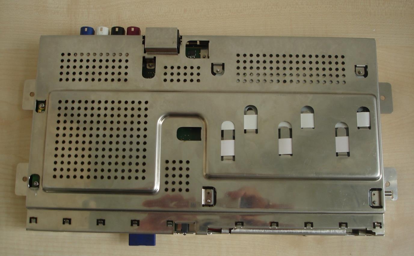
External Images of Body Connectivity unit (BCU) 1 CONFIDENTIAL External Images Front Top External Images of Body Connectivity unit (BCU) 2 CONFIDENTIAL Bottom RH External Images of Body Connectivity unit (BCU) 3 CONFIDENTIAL LH Rear

ID Label/Location Info

This device complies with part 15 of the FCC Rules: Operation is subject to the following two conditions: (1) This device may not cause harmful interference, and (2) this device must accept any interference received, including interference that may cause undesired operation. 70x50mm - height 5mm FCC ID:2AAKLD189070 IC: 11196A-D189070 XXXXXXX XXXXXXX CMIIT ID:XXXXXXX - outer size 8x6.3mm R DDDLLDDDDDDDD R DDDLLDDDDDDDD - Japan - min 5mm - R - group TBC, D digit L - letter ZZZZZ : Certification Body code assigned by OFCA YY : Year of issue XXXXX : Serial number of certificate issued during that calendar year KCC-CRM-ABC-XXXXXXXXXXXXXX 70x45mm Bentley Homologation label BCU 4W0 907 157 X Damian Trybuszewski 06.11.2013 For Author Title Date V7 V1 V2 First release - draft 14.04.2013 FCC ID and IC ID added 02.10.2013 FCC logo removed, IC ID corrected (1 was missing) 04.10.2013 Bottom BCU metal surface Can be printed as one label 70x 95mm Note: Self adhesive labels according to TL 520 38 10mm ± 3mm Contains FCC ID: NCMOMO6812 Contains IC: 2734A-MO6812 V3 V4 V5 V6 V7 NAL licence added 29.10.2013 IC ID corrected to IC 30.10.2013 Chinese "Made in Germany" and input voltage added 04.11.2013 For CCC "S&E" added, CD symbol added, Chinese translation added 06.11.2013 NAL Licence no: 00-0000-000000 Model no. 0000000 Control no.000000000000000 SE + SE + / Model: D189070 Input: 9.5 16V DC / Name: / RSE Control Unit Made in Germany This device complies with part 15 of the FCC Rules: Operation is subject to the following two conditions: (1) This device may not cause harmful interference, and (2) this device must accept any interference received,including interference that may cause undesired operation. FCC ID:2AAKLD189070IC: 11196A-D189070 XXXXXXX XXXXXXX CMIIT ID:XXXXXXX R DDDLLDDDDDDDD KCC-CRM-ABC-XXXXXXXXXXXXXX Contains FCC ID: NCMOMO6812Contains IC: 2734A-MO6812 NAL Licence no: 00-0000-000000Model no. 0000000 Control no.000000000000000 S E + / Model: D189070 Input: 9.5 16V DC / Name: / RSE Control Unit Made in Germany

Internal Photos

Internal Product Images of Body Connectivity unit (BCU) 1 CONFIDENTIAL Internal Images BCU PCB Top View Internal Product Images of Body Connectivity unit (BCU) 2 CONFIDENTIAL Heim Board Top View Heim Board Bottom View Internal Product Images of Body Connectivity unit (BCU) 3 CONFIDENTIAL Heim Board Bottom View 2 Heim Board Top View 2 Internal Product Images of Body Connectivity unit (BCU) 4 CONFIDENTIAL WLAN / BT Module Internal Product Images of Body Connectivity unit (BCU) 5 CONFIDENTIAL BCU Top view 1 BCU Top view 2 Internal Product Images of Body Connectivity unit (BCU) 6 CONFIDENTIAL BCU Bottom View 1 WLAN – UMTS Antenna Fakra connection

RF Exposure Info

Page 1 of 7 RF Exposure and Transmitter Power Considerations for the Audiovox Incaar Systems BCU (includes Option GTM681W module) FCC ID: 2AAKLD189070 Analysis for FCC Mobile use The FCC requires that the calculated MPE be equal to or less than a given limit dependent on frequency at a distance of 20 cm from a device to the body of a user. The transmitter operation for the Audiovox Incaar Systems BCU covers 850 MHz, 1750 MHz, 1900 MHz and 2.4 GHz operating bands using GSM, CDMA, UMTS, Bluetooth and Wi-Fi technologies. The following FCC Rule Parts and procedures are applicable: Part 1.1310 – Radiofrequency radiation exposure limits Part 2.1091 – Radiofrequency radiation exposure evaluation: mobile devices Part 15.247(b)(1) - For frequency hopping systems operating in the 2400–2483.5 MHz band employing at least 75 non-overlapping hopping channels, and all frequency hopping systems in the 5725–5850 MHz band: 1 watt. Part 15.247(b)(3) - For systems using digital modulation in the 902–928 MHz, 2400–2483.5 MHz, and 5725–5850 MHz bands: 1 Watt. Part 15.247(b)(4) - The conducted output power limit specified in paragraph (b) of this section is based on the use of antennas with directional gains that do not exceed 6 dBi. Part 22.913(a)(2) The ERP of mobile transmitters and auxiliary test transmitters must not exceed 7 Watts. Part 24.232(c) Mobile/ Portable stations are limited to 2 Watts EIRP peak power. Part 27.50(d)(4) Fixed, mobile, and portable (handheld) stations operating in the 1710–1755 MHz band are limited to 1 watt EIRP. KDB447498 D01 v05 Mobile and Portable Devices RF Exposure Procedures and Equipment Authorisation Policies The MPE calculation S = EIRP/4 π R2 is used to calculate the safe operating distance for the user. Page 2 of 7 MAXIMUM TRANSMITTER POWER CONSIDERATIONS 850 MHz Operation For GSM 850MHz Transmitter frequency range = 824 MHz to 849 MHz Conducted power = 33 dBm (2000 mW) Maximum specified antenna gain = 2.15 dBi EIRP = 33 + 2.15 dBm = 35.15 dBm = 3273 mW For Class 10 GPRS/ EGPRS with 2 uplink timeslots, duty cycle = 25% EIRP eff = 3273/4 = 818 mW (With consideration of source based time averaging as per KDB 447498 Section 4.1(2)) ERP = 35.15 (EIRP) - 2.2 (dipole gain) = 32.95 dBm = 1972 mW For Class 10 GPRS/ EGPRS with 2 uplink timeslots, duty cycle = 25% ERP eff = 1972/4 = 493 mW For UMTS Band V 850 MHz Transmitter frequency range = 824 MHz to 849 MHz Conducted power = 24 dBm (251 mW) Maximum specified antenna gain = 2.15 dBi EIRP = 24 + 2.15 dBm = 26.15 dBm = 412 mW ERP = 26.15 (EIRP) - 2.2 (dipole gain) = 23.95 dBm = 248 mW ERP = 248 mW Therefore the Audiovox Incaar Systems BCU meets Part 22.913(a)(2) power limits (ERP 7 Watts). Also the categorical exclusion provision of FCC Part 2.1091(c) applies as ERP < 1.5W. 1750 MHz Operation For CDMA 1750 MHz Transmitter frequency range = 1710 MHz to 1755 MHz Conducted Power = 24 dBm (251 mW) Maximum specified antenna gain = 2.15 dBi EIRP = 24 + 2.15 dBm = 26.15 dBm = 412 mW EIRP = 412 mW Therefore the Audiovox Incaar Systems BCU meets 27.50(d)(4) power limits (EIRP 1 Watt). Also the categorical exclusion provision of FCC Part 2.1091(c) applies as EIRP < 3.0W. Page 3 of 7 1900 MHz Operation For PCS 1900 MHz Transmitter frequency range = 1850 MHz to 1910 MHz Conducted Power = 30 dBm (1000 mW) Maximum specified antenna gain = 2.15 dBi EIRP = 30 + 2.15 dBm = 32.15 dBm = 1641 mW For Class 10 GPRS with 2 uplink timeslots, duty cycle = 25% EIRP eff = 1641/4 = 410 mW (With consideration of source based time averaging as per KDB 447498 Section 4.1(2)) For UMTS Band II 1900 MHz Transmitter frequency …

Text truncated - open the document above for the full version.

Contact Information

Applicant

Damian Trybuszewski
[email protected]441483722531Fax: 44 1483 740 204

Technical Contact

Audiovox Incaar Systems GmbHDamian Trybuszewski
[email protected]441483722531

Unit 14 Boundary Business Centre · Woking · United Kingdom

Non-Technical Contact

Audiovox Incaar Systems GmbHDamian Trybuszewski
[email protected]441483722531

Test Firm

UL VS LtdDarren Rust
[email protected]+44 1256 31 2119Fax: +44 1256 31 2001

Technical Specifications

#Rule PartsFrequency RangePower Output
115C2.41 GHz - 2.46 GHz66.00 mW
Confidentiality
Long Term
Grant Notes
Power is conducted. Only the antenna(s) tested with the device or similar antenna(s) with equal or lesser gain may be used with this transmitter. For satisfying FCC rule part 2.1091, RF exposure compliance, this device must be used at a distance of at least 20 cm from all persons. The antennas must not be co-located or operating in conjunction with any other antenna or transmitter, except as detailed in this filing. End-users and installers must be provided with antenna installation instructions and transmitter operating conditions for satisfying RF exposure compliance. Approved for use with integrated module FCC ID: NCMOMO6812

Other Applications from Audiovox Incaar Systems GmbH

Rear Seat Entertainment System DVD Loader - FCC ID 2AAKLD189050 - Audiovox Incaar Systems GmbH
2AAKLD189050

Rear Seat Entertainment System DVD Loader

Apr 28, 2014

Equipment Class

DTS - Digital Transmission System