2AALLWPJ2530CZIGBEE COORDINATOR
ASK PROXIMA CO., LIMITED
Click to zoom
Application Details
- Equipment Class
- DXX - Part 15 Low Power Communication Device Transmitter
- Date of Grant
- Mar 03, 2014
- Application Purpose
- Original Equipment
- Date of Application
- Mar 03, 2014
- Equipment Note
- ZIGBEE COORDINATOR
- Frequency Range
- 2460.00000000 - 2460.00000000
- Company
- ASK PROXIMA CO., LIMITED
- Country
- Hong Kong
Documents & Files
Document Text
Text extracted from the exhibit documents filed with the FCC. Open a document above to read the original.
Users Manual
ZIGBEE network operating instructions 1.PC with Zigbee module, plug in the computer corner has the following tips, the diagram below: 2.Install the driver, the following figure Open the "CP210x driven" file, double‐click the file under "CP210xVCPInstaller. Exe file, click on the" Install ", as follows; Click on the "ok" of the displayed after the installation is successful, after the driver installation is complete, as follows: 1、 Check the COM, the right mouse button click on the "computer", then click "management", select "device manager", the following figure: After opening the "port (COM and LPT)" item, see“Silicon Labs CP210x USB to UART Bridge (COM7)”Words, COM7 is our the port to be used。 Open the "projectorWLAN. Exe file(note: if it is Windows 7 or Window8 system, select "run as administrator" and "run in compatibility mode") Right click on the "projectorWlAN" | | attribute compatibility, as shown in figure: 2、 Point after "ok" to open "projectorWLAN. Exe", appear below the window: The menu bar can be switch in both Chinese and English: “AUTO”Set to "device manager" see COM7, selected to point "connection", after the green icon appears after the connection is successful, respectively, the following figure: n the box on the left "the Read/Write" input "1‐200" digital, from any one of the I type 2, for example, the following figure. "Write", appear below the window, some "ok"。 Point after "ok", pull out the Zigbee module, and then reinsert the computer。 "Connected", then click "network" blank space under the PAN ID window will appear number 2, below: 3、 Open the projector, according to the remote control, find "Zigbee set", press "OK" to enter, as follows: Sets the "Zigbee mode" to "open", press "OK" button on the remote control;Will be set to "PAN ID" and the computer terminal window under the same "2" and press "OK" button on the remote control, the following figure: To connect to the Internet, select menu of "join Zigbee network" projector press "OK" button on the remote control, waiting for the interface, the following figure: After joining the network in the computer side application window under the "ID" will automatically appear in a code, see below 26713: 6、After the success of the network, double‐click the window under the "26713" the projector to do "normal, KeySton, LenzShift, fusion splicing" operation, the following figure: When entering "Lenzshift", whenever shift in one direction, should be first "coarse" button operation, such as: the Up +, Do +, Le +, Ri +, then adjust "fine tuning" buttons, such as: Up,Do,Le,Ri. FCC Notice This device complies with Part 15 of the FCC Rules. Operation is subject to the following two conditions: (1) This device may not cause harmful interference, and (2) this device must accept any interference received, including interference that may cause undesired operation. NOTE 1: This equipment has been tested and found to comply with the limits for a Class B digital device, pursuant to part 15 of the FCC Rules. These limits are designed to provide reasonable protection against harmful interference in a residential installation. This equipment generates, uses and can radiate radio frequency energy and, if not installed and used in accordance with the instructions, may cause harmful interference to radio communications. However, there is no guarantee that interference will not occur in a particular installation. If this equipment does cause harmful interference to radio or television reception, which can be determined by turning the equipment off and on, the user is encouraged to try to correct the interference by one or more of the following measures: ‐ Reorient or relocate the receiving antenna. ‐ Increase the separation between the equipment and receiver. ‐Connect the equipment into an outlet on a circuit different from that to which the receiver is connected. ‐Consult the dealer or an experienced radio/TV technician for help. NOTE 2: Any changes or modifications to this unit not expressly approved by the party responsible for compliance could void the user's authority to operate the equipment.
Cover Letter(s)
ASK PROXIMA CO., LIMITED Room 3, 21/F., Far East Consortium Building, 121 Des Voeux Road, Central, Hong Kong --------------------------------------------------------------------------------------------------------------------- Federal Communications Commission Authorization and Evaluation Division Confidentiality Request regarding application for certification of FCC ID: 2AALLWPJ2530C Pursuant to Sections 0.457 and 0.459 of the Commission’s Rules, we hereby request confidential treatment of information accompanying this application as outlined below: Exhibit Type File Name Schematics 2AALLWPJ2530C_FCCID_Schematics Block Diagram 2AALLWPJ2530C_BlockDiagram Operational Description 2AALLWPJ2530C_OperationalDescription The above materials contain trade secrets and proprietary information not customarily released to the public. The public disclosure of these materials may be harmful to the applicant and provide unjustified benefits to its competitors. The applicant understands that pursuant to Section 0.457 of the Rules, disclosure of this application and all accompanying documentation will not be made before the date of the Grant for this application. Sincerely, ASK PROXIMA CO., LIMITED ------------------------- (Roy Guo) (Certification Engineer)
Cover Letter(s)
ASK PROXIMA CO., LIMITED Room 3, 21/F., Far East Consortium Building, 121 Des Voeux Road, Central, Hong Kong -------------------------------------------------------------------------------- (FCC ID:2AALLWPJ2530C) POWER OF ATTORNEY DATE: 2014-01-17 Federal Communications Commission Authorization and Evaluation Division 7435 Oakland Mills Road Columbia, MD 21046 To Whom It May Concern: We, the undersigned, hereby authorize Shenzhen SEM.Test Technology Co., Ltd. Jandy So on our behalf, to apply to the Federal Communications Commission on our equipment. Any and all acts carried out by Shenzhen SEM.Test Technology Co., Ltd. Jandy So on our behalf shall have the same effect as acts of our own. This is to advise that we are in full compliance with the Anti-Drug Abuse Act. We, ASK PROXIMA CO., LIMITED are not subject to a denial of federal benefits pursuant to Section 5301 of the Anti-Drug Act of 1988, 21 USC853a, and no party to the application is subject to a denial of federal benefits pursuant to that section. Sincerely, ASK PROXIMA CO., LIMITED ------------------------- (Roy Guo) (Certification Engineer)
External Photos
ASK PROXIMA CO., LIMITED Model: WPJ2530C REPORT NO.: STR13128110I-1 FCC PART 15.247 EXHIBIT 2 - EUT EXTERNAL PHOTOGRAPHS EUT View 1 EUT View 2 ASK PROXIMA CO., LIMITED Model: WPJ2530C REPORT NO.: STR13128110I-1 FCC PART 15.247 EUT View 3 EUT View 4 ASK PROXIMA CO., LIMITED Model: WPJ2530C REPORT NO.: STR13128110I-1 FCC PART 15.247 EUT View 5 EUT View 6
ID Label/Location Info
ASK PROXIMA CO., LIMITED Model: WPJ2530C REPORT NO.: STR13128110I-1 FCC PART 15.247 EXHIBIT 1 - PRODUCT LABELING Proposed FCC ID Label Format FCC ID: 2AALLWPJ2530C Specifications: Text is Black in color and justified. Labels are printed in indelible ink on permanent adhesive silk-screened onto the EUT or shall be affixed at a conspicuous location on the EUT. Proposed Label Location on EUT FCC ID Label Location
ID Label/Location Info
ASK PROXIMA CO., LIMITED Model: WPJ2530C REPORT NO.: STR13128110I-1 FCC PART 15.247 EXHIBIT 1 - PRODUCT LABELING Proposed FCC ID Label Format FCC ID: 2AALLWPJ2530C Specifications: Text is Black in color and justified. Labels are printed in indelible ink on permanent adhesive silk-screened onto the EUT or shall be affixed at a conspicuous location on the EUT. Proposed Label Location on EUT FCC ID Label Location
Internal Photos
ASK PROXIMA CO., LIMITED Model: WPJ2530C REPORT NO.: STR13128110I-1 FCC PART 15.247 EXHIBIT 3 - EUT INTERNAL PHOTOGRAPHS EUT Housing and Board View 1 Solder Board-Component View 1 Ant. 2460MHz ASK PROXIMA CO., LIMITED Model: WPJ2530C REPORT NO.: STR13128110I-1 FCC PART 15.247 Solder Board-Component View 2
Test Report
ASK PROXIMA CO., LIMITED Model: WPJ2530C REPORT NO.: STR13128115I PAGE 1 OF 22 FCC PART 15.249 FCC Part 15C Measurement and Test Report For ASK PROXIMA CO., LIMITED Room 3, 21/F., Far East Consortium Building, 121 Des Voeux Road, Central, Hong Kong FCC ID: 2AALLWPJ2530C FCC Rule(s): FCC Part 15.249 Product Description: Zigbee Coordinator Tested Model: WPJ2530C Report No.: STR13128111I Tested Date: 2013-12-10 to 2014-01-10 Issued Date: 2014-01-13 Tested By: Daniel Liu / Engineer Reviewed By: Lahm Peng / EMC Manager Approved & Authorized By: Jandy so / PSQ Manager Prepared By: Shenzhen SEM.Test Technology Co., Ltd. 1/F, Building A, Hongwei Industrial Park, Liuxian 2nd Road, Bao'an District, Shenzhen, P.R.C.(518101) Tel.: +86-755-33663308 Fax.: +86-755-33663309 Website: www.semtest.com.cn Note: This test report is limited to the above client company and the product model only. It may not be duplicated without prior permitted by Shenzhen SEM.Test Technology Co., Ltd. ASK PROXIMA CO., LIMITED Model: WPJ2530C REPORT NO.: STR13128115I PAGE 2 OF 22 FCC PART 15.249 TABLE OF CONTENTS 1. GENERAL INFORMATION ................................................................................................................................... 3 1.1 PRODUCT DESCRIPTION FOR EQUIPMENT UNDER TEST (EUT) ............................................................................... 3 1.2 TEST STANDARDS ................................................................................................................................................... 4 1.3 TEST METHODOLOGY ............................................................................................................................................. 4 1.4 TEST FACILITY ....................................................................................................................................................... 4 1.5 EUT SETUP AND TEST MODE ................................................................................................................................. 5 2. SUMMARY OF TEST RESULTS ........................................................................................................................... 6 3. ANTENNA REQUIREMENTS ................................................................................................................................ 7 3.1 STANDARD APPLICABLE ......................................................................................................................................... 7 3.2 TEST RESULT.......................................................................................................................................................... 7 4. RADIATED EMISSIONS ......................................................................................................................................... 8 4.1 MEASUREMENT UNCERTAINTY .............................................................................................................................. 8 4.2 STANDARD APPLICABLE ......................................................................................................................................... 8 4.3 TEST EQUIPMENT LIST AND DETAILS ..................................................................................................................... 8 4.4 TEST PROCEDURE ................................................................................................................................................... 9 4.5 CORRECTED AMPLITUDE & MARGIN CALCULATION .............................................................................................. 9 4.6 ENVIRONMENTAL CONDITIONS ............................................................................................................................ 10 4.7 SUMMARY OF TEST RESULTS/PLOTS .................................................................................................................... 10 5. OUT OF BAND EMISSIONS ................................................................................................................................. 14 5.1 STANDARD APPLICABLE ....................................................................................................................................... 14 5.2 TEST EQUIPMENT LIST AND DETAILS ................................................................................................................... 14 5.3 TEST PROCEDURE ................................................................................................................................................. 14 5.4 ENVIRONMENTAL CONDITIONS ............................................................................................................................ 14 5.5 SUMMARY OF TEST RESULTS/PLOTS .................................................................................................................... 14 6. EMISSION BANDWIDTH ..................................................................................................................................... 17 6.1 STANDARD APPLICABLE ....................................................................................................................................... 17 6.2 TEST EQUIPMENT LIST AND DETAILS ................................................................................................................... 17 6.3 TEST PROCEDURE ................................................................................................................................................. 17 6.4 ENVIRONMENTAL CONDITIONS ............................................................................................................................ 17 6.5 SUMMARY OF TEST RESULTS/PLOTS .................................................................................................................... 17 7. CONDUCTED EMISSIONS ..............................................................................................................…
Text truncated - open the document above for the full version.
Test Setup Photos
ASK PROXIMA CO., LIMITED Model: WPJ2530C REPORT NO.: STR13128110I-1 FCC PART 15.247 EXHIBIT 4 - TEST SETUP PHOTOGRAPHS Conducted Emission Test Setup Radiation Emission Test Setup (30MHz to 1GHz) ASK PROXIMA CO., LIMITED Model: WPJ2530C REPORT NO.: STR13128110I-1 FCC PART 15.247 Radiation Emission Test Setup (Above 1GHz)
Contact Information
Applicant
Roy Guo(Engineer)
Test Firm
SEM.Test Compliance Service Co., Ltd.Jandy So
Technical Specifications
| # | Rule Parts | Frequency Range | Power Output |
|---|---|---|---|
| 1 | 15C | 2.46 GHz - 2.46 GHz | - |
Other Applications from ASK PROXIMA CO., LIMITED

2AALLWPJ2530R
Mar 04, 2014ZIGBEE ROUTER
Equipment Class
DXX - Part 15 Low Power Communication Device Transmitter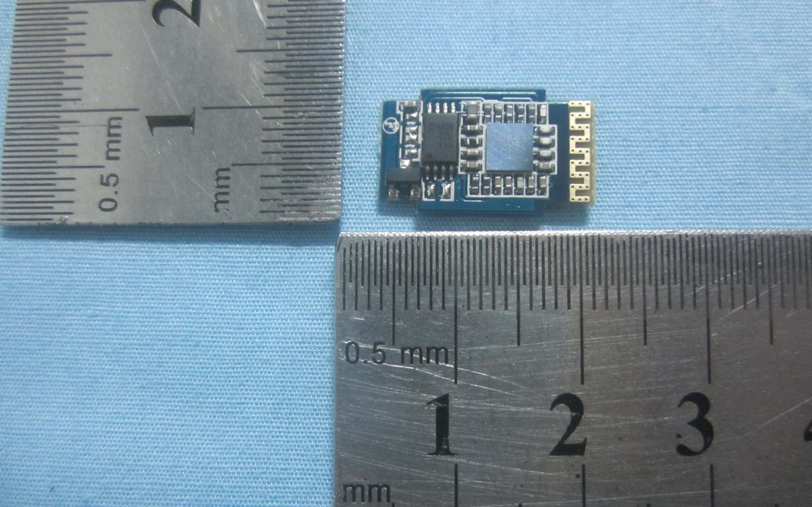
2AALL968
Nov 06, 2013BLUETOOTH DONGLE
Equipment Class
DSS - Part 15 Spread Spectrum Transmitter
2AALLDCF
Nov 05, 2013BLUETOOTH MODULE
Equipment Class
DSS - Part 15 Spread Spectrum Transmitter