2AAMI-T2400Satori smart
Garmin International, Inc.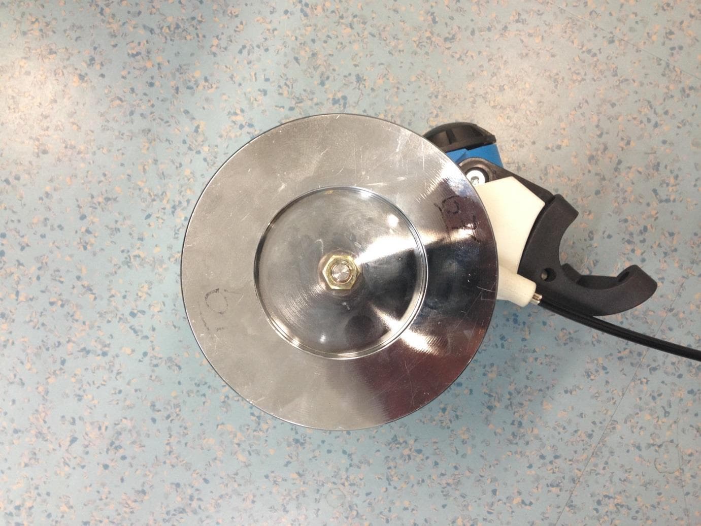
Click to zoom
Application Details
- Equipment Class
- DTS - Digital Transmission System
- Date of Grant
- Oct 05, 2014
- Application Purpose
- Original Equipment
- Date of Application
- Oct 05, 2014
- Equipment Note
- Satori smart
- Frequency Range
- 2402.00000000 - 2480.00000000
- Company
- Garmin International, Inc.
- Country
- United States
Documents & Files
Document Text
Text extracted from the exhibit documents filed with the FCC. Open a document above to read the original.
Users Manual
Concept manual Tacx T2400 Satori Smart Final version will be available in 16 languages Company Logo Logo’s Manual Safety precautions: This device is not designed for industrial ,medical or commercial applications. Do not expose the product to water or moisture. [additional remarks will appear, specific warning for flywheel in relation to heat] Instructions [will be added later] Maintenance: Clean only with a dry cloth. Do not use cleaning solvents or abrasives. [additional remarks will appear] Warranty: No guarantee or liability can be accepted for any changes and modifications of the product or damage caused due to incorrect use of this product. [additional information will appear, warranty period 2 years] Service [instructions] For service contact: [Adres] Tacx b.v. Rijksstraatweg 52 2241BW Wassenaar The Netherlands General: Designs and specifications are subject to change without notice. All logos brands and product names are trademarks or registered trademarks of their respective holders and are hereby recognized as such. This manual was produced with care. However, no rights can be derived. Tacx cannot accept liability for any errors in this manual or their consequences. Changes or modifications not expressly approved by the party responsible for compliance could void the user's authority to operate the equipment. Keep this manual and packaging for future reference. Specifications: [will be added later] Braking capacities RF communication Protocols, BT and ANT+ Frequency Output power Batteries Temperature range , operational -20°C to + 55°C FCC and IC Declarations Your device contains a low power transmitter. When device is transmitting it sends out Radio Frequency (RF) signals. In order to maintain compliance with the FCC and RF exposure guidelines, this equipment should be installed and operated with minimum distance of 20cm between the radiator and your body. Unauthorized modification, or attachments could damage the transmitter and may violate FCC regulations This device complies with part 15 of the FCC Rules. This device complies with the Industry Canada licence-exempt RSS standard(s). Operation is subject to the following two conditions: (1) This device may not cause harmful interference. (2) This device must accept any interference received, including interference that may cause undesired operation. CE Declaration of Conformity For the following equipment: Product name: Tacx T2400 Satori Smart Tacx bv hereby declares that this product conforms to the essential requirements set out in the Council (European parliament) Directive and other relevant provisions. 99/5/EG Radio equipment and telecommunications terminal equipment 2004/108/EG Electromagnetic Compatibility 2006/95/EG Low Voltage Directive 2011/65/EG RoHS , Restriction of Hazardous Substances A copy of this declaration is available on the Tacx website: www.tacx.com Attention: This product is marked with this symbol. It means that used electrical and electronic products should not be mixed with general household waste. There is a separate collections system for these products.
External Photos
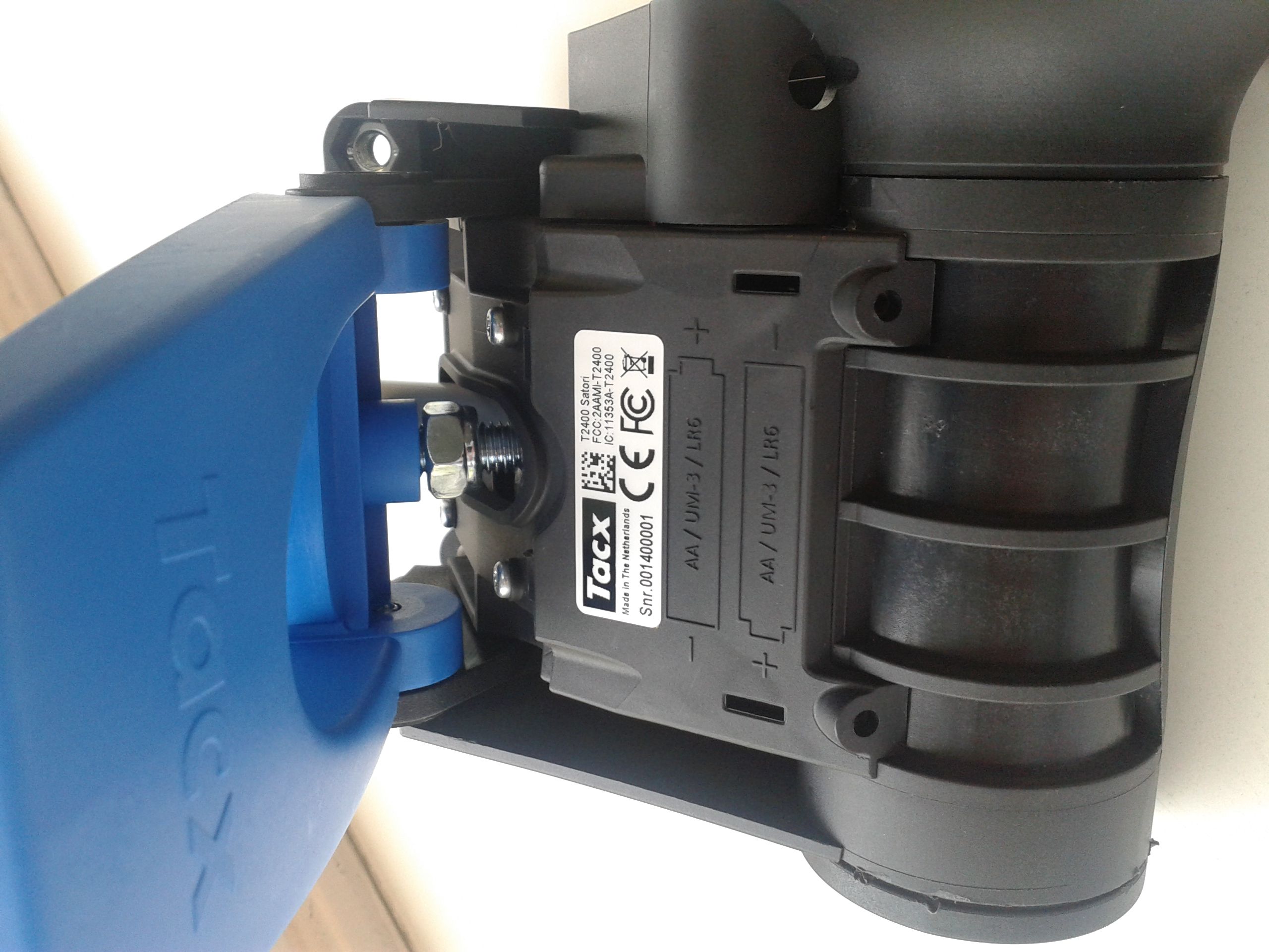
Product top view Electronics main pcb E lectronics sensor pcb Right View Satori Smart Bottom View Batteries (2 * ”AA”) Left view Identification label Angled view
External Photos
Tacx T2400 Satori smart 5 june 2014 Batteries and main PCB Sensor PCB is connected with flex tail to main PCB Sensor PCB and location of on switch
ID Label/Location Info
38.00 19.00
Internal Photos
Tacx T2400 Satori smart 13 june 2014 PCB top view Left is the main board with microcontroller and RF circuit. Right the sensor pcb with flextail tot the main board. PCB bottom view A test label will be added on the copper area for production traceability
Test Report
A Radio Test Report FOR TACX BV ON Satori Smart DOCUMENT NO. TRA-021371WUS1a Total number of pages : 80 TRaC Wireless Test Report : TRA-021371WUS1a Applicant : TACX BV Apparatus : Satori Smart Specification(s) : CFR47 Part 15.247 (October 2013 Edition) IC RSS-210 Annex 8 Issue 8 (December 2010) FCCID : 2AAMI-T2400 ICID : 11353A-T2400 Purpose of Test : Certification Authorised by : : Radio Product Manager Issue Date :26 th September 2014 Authorised Copy Number : PDF TRaC Global Test Report: TRA-021371WUS1a 3 Contents Section 1: Introduction 4 1.1 General 4 1.2 Tests Requested By 5 1.3 Manufacturer 5 1.4 Apparatus Assessed 6 1.5 Test Result Summary 7 1.6 Notes Relating To The Assessment 8 1.7 Deviations from Test Standards 8 Section 2: Measurement Uncertainty 9 2.1 Application of Measurement Uncertainty 9 2.2 Measurement Uncertainty Values 10 Section 3: Modifications 11 3.1 Modifications Performed During Assessment 11 Section 4 General Test Procedures 12 4.1 Radiated Test Setup and Procedures 12 4.2 AC Powerline Conducted Emissions Test Setup and Procedures 13 4.3 Antenna Port Conducted Emissions 13 4.4 Power Supply Variation 14 4.5 Thermal Variation 14 4.6 Time Domain Measurements 14 Appendix A: Formal Emission Test Results 15 A1 6 dB Bandwidth 16 A2 Transmitter Peak Output Power 17 A3 Transmitter Power Spectral Density 18 A4 Lower Band-Edge Compliance 19 A5 Radiated Electric Field Emissions within the Restricted Bands of 15.205 20 A7 Antenna Gain 25 A8 Unintentional Radiated Electric Field Emissions - 15.109 26 Appendix B: Supporting Graphical Data 29 Appendix C: Additional Test and Sample Details 53 Appendix D: Additional Information 59 Appendix E: Photographs and Figures 75 Appendix G: General SAR test reduction and exclusion guidance and MPE calculation 78 TRaC Global Test Report: TRA-021371WUS1a 4 Section 1: Introduction 1.1 General This report contains an assessment of an apparatus against Electromagnetic Compatibility Standards based upon tests carried out on samples submitted to the Laboratory. Test performed at: TRaC Global [X] Unit E South Orbital Trading Park Hedon Road Hull, HU9 1NJ. United Kingdom. Telephone: +44 (0) 1482 801801 Fax: +44 (0) 1482 801806 TRaC Global [ ] Unit 1 Pendle Place Skelmersdale West Lancashire, WN8 9PN United Kingdom Telephone: +44 (0) 1695 556666 Fax: +44 (0) 1695 577077 Email: [email protected] Web site: http://www.tracglobal.com Tests performed by: A Longley Report author: A Longley This report must not be reproduced except in full without prior written permission from TRaC Global. TRaC Global Test Report: TRA-021371WUS1a 5 1.2 Tests Requested By This testing in this report was requested by : TACX BV Rijksstraatweg 52 Wassenaar Netherlands 2241 BW 1.3 Manufacturer As above TRaC Global Test Report: TRA-021371WUS1a 6 1.4 Apparatus Assessed The following apparatus was assessed between the 12 th June 2014 and the 28 th July 2014: Satori Smart The apparatus was a roller mechanism for converting a conventional bicycle into a stationary exercise bike, the apparatus contained a Bluetooth Low Energy transceiver to communicate information from the roller to exercise software on a Bluetooth device. The apparatus can also communicate in ANT+ mode, the ANT+ assessment is not detailed in this report. TRaC Global Test Report: TRA-021371WUS1a 7 1.5 Test Result Summary Full details of test results are contained within Appendix A. The following table summarises the results of the assessment. The statements relating to compliance with the standards below apply ONLY as qualified in the notes and deviations stated in sections 1.6 to 1.7 of this test report. Full details of test results are contained within Appendix A. The following table summarises the results of the assessment. Test Type Regulation Measurement standard Result Radiated spurious emissions Title 47 of the CFR: Part 15 Subpart C; 15.247 IC RSS-210 A8.5 ANSI C63.10:2009 Pass Lower Band Edge emissions (Non-restricted bands) Title 47 of the CFR: Part 15 Subpart C; 15.247 IC RSS-210 A8.5 ANSI C63.10:2009 Pass Occupied Bandwidth Title 47 of the CFR : Part 15 Subpart C; 15.247(a)(2) IC RSS-210 A8.2 (a) ANSI C63.10:2009 Pass Carrier Power Title 47 of the CFR : Part 15 Subpart C; 15.247(b) IC RSS-210 A8.4 (4) ANSI C63.10:2009 Pass Power Spectral Density Title 47 of the CFR : Part 15 Subpart C; 15.247(e) IC RSS-210 A8.2 (b) ANSI C63.10:2009 Pass Unintentional Radiated Spurious Emissions Title 47 of the CFR: Part 15 Subpart B; 15.109 IC RSS-210 A8.5 ANSI C63.10:2009 Pass RF Safety Title 47 of the CFR : Part 15 Subpart C; 15.247(b)(5) - - - Abbreviations used in the above table: Mod : Modification CFR : Code of Federal Regulations ANSI : American National Standards Institution REFE : Radiated Electric Field Emissions PLCE : Power Line Conducted Emissions TRaC Global Test Report: TRA-021371WUS1a 8 1.6 Notes Relating To The Assessment With regard to this assessment, the following points should be noted: The results contained in this report relate only to the items tested and were obtained in the period between the date of initial receipt of samples and the date of issue of the report. The apparatus was set up and exercised using the configurations, modes of operation and arrangements defined in this report only. Particular operating modes, apparatus monitoring methods and performance criteria required by the standards tested to have been performed except where identified in Section 1.7 of this test report (Deviations from Test Standards). For emissions testing, throughout this test report, “Pass” indicates that the results for the sample as tested were below the specified limit (refer also to Section 2, Measurement Uncertainty). Where relevant, the apparatus was only assessed using the monitoring methods and susceptibility criteria defined in this report. All testing with the exception of testing at the Open Area Test Site was performed under the following environmental conditions: Temperature : 17 to 23 °C Humidity …
Text truncated - open the document above for the full version.
Contact Information
Applicant
Ben Karsak(Manager Compliance Engineering)
Test Firm
Element Materials Technology Warwick LtdMax Leach
Technical Specifications
| # | Rule Parts | Frequency Range | Power Output |
|---|---|---|---|
| 1 | 15C | 2.40 GHz - 2.48 GHz | 300.00 µW |
Other Applications from Garmin International, Inc.
2AAMI-T2080
Nov 11, 2015Motorbrake with Wireless Data Transfer
Equipment Class
DTS - Digital Transmission System
2AAMI-T2800
Sep 01, 2015Wireless Communication System
Equipment Class
DXX - Part 15 Low Power Communication Device Transmitter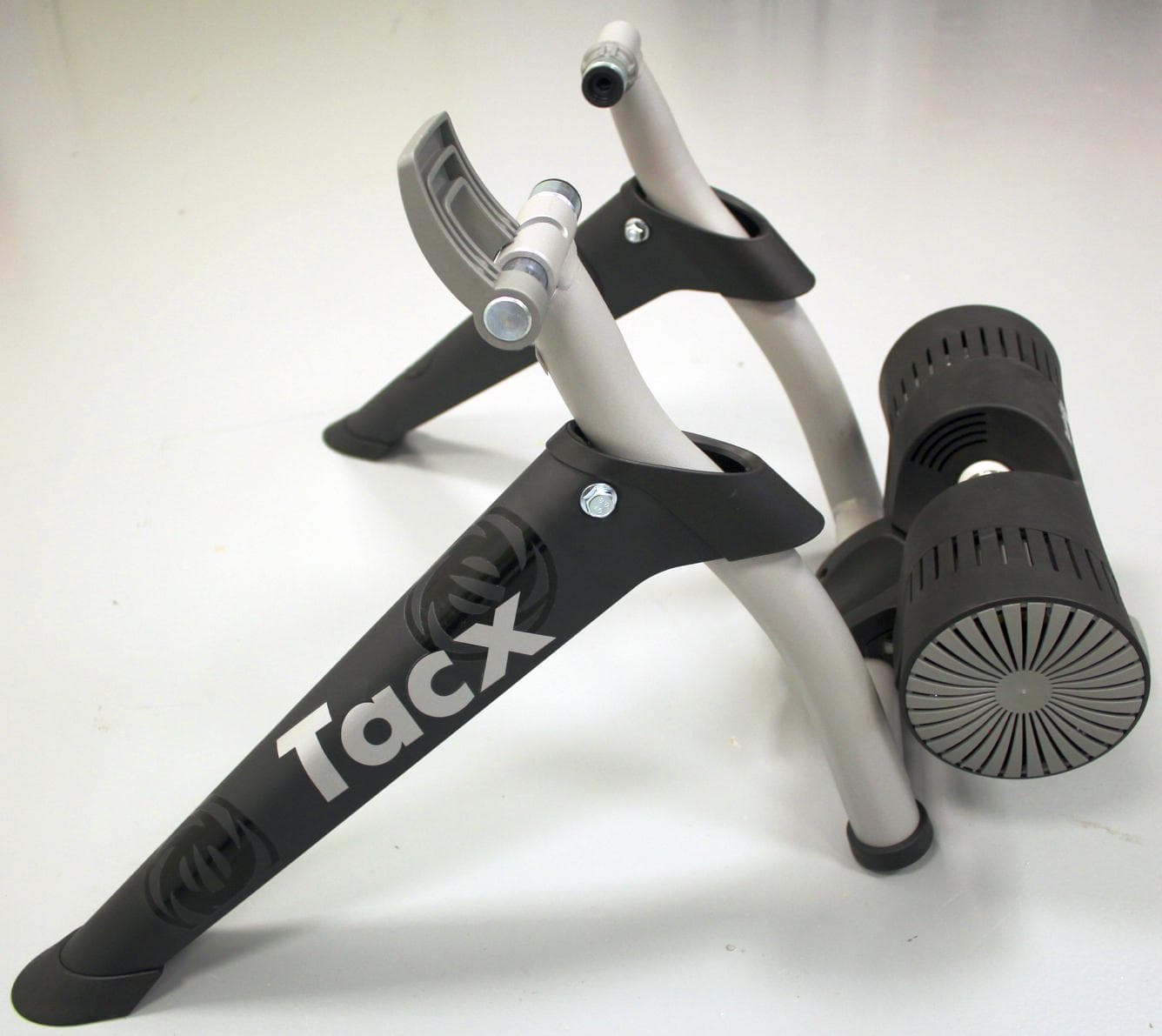
2AAMI-T2780
Feb 18, 2015Wireless Communication System
Equipment Class
DXX - Part 15 Low Power Communication Device Transmitter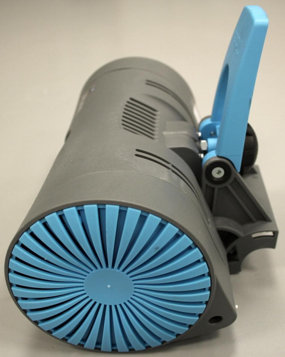
2AAMI-T2180
Jan 18, 2015Wireless Communication System
Equipment Class
DTS - Digital Transmission System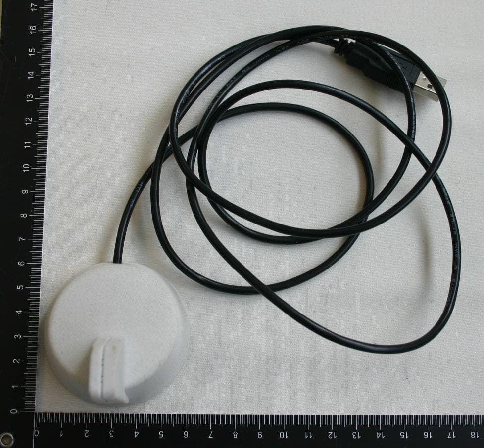
2AAMI-T2028
Sep 29, 2013USB Antenna
Equipment Class
DTS - Digital Transmission System