2AANA-SEM-SP2900Mini Speaker
S.E.M. INDUSTRIES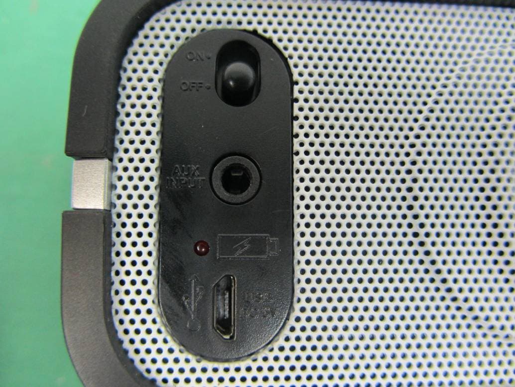
Click to zoom
Application Details
- Equipment Class
- DXX - Part 15 Low Power Communication Device Transmitter
- Date of Grant
- Aug 05, 2014
- Application Purpose
- Original Equipment
- Date of Application
- Aug 04, 2014
- Equipment Note
- Mini Speaker
- Frequency Range
- 2402.00000000 - 2480.00000000
- Company
- S.E.M. INDUSTRIES
- Country
- China
Documents & Files
Document Text
Text extracted from the exhibit documents filed with the FCC. Open a document above to read the original.
Users Manual
High Power Mini Speaker System OPERATING INSTRUCTIONS MODEL : SP-2900-BT E-2 WARNING: To reduce the risk of electric shock, do not remove cover (or back). No user-serviceable parts inside. Refer servicing to qualified service personnel. CAUTION RISK OF ELECTRIC SHOCK DO NOT OPEN The exclamation point within the triangle is a warning sign alerting you of important instructions accompanying the product. The lightning flash and arrowhead within the triangle is a warning sign alerting you of "dangerous voltage" inside the product. NOTE: CAUTION SYMBOLS ARE PRINTED ON REAR OF UNIT. PLEASE REFER TO INSTRUCTION MANUAL. WARNING:TO REDUCE THE RISK OF FIRE OR ELECTRIC SHOCK, DO NOT EXPOSE THIS APPLIANCE TO DRIPPING OR SPLASHING LIQUIDS. THE APPARATUS SHOULD NOT BE EXPOSED TO DRIPPING OR SPLASHING AND NO OBJECTS FILLED WITH LIQUIDS SHOULD BE PLACED ON THE APPARATUS. THE MARKING AND RATING LABEL IS LOCATED AT REAR ENCLOSURE OF THE APPARATUS. UNDER THE INFLUENCE OF ELECTROSTATIC PHENOMENON, THE PRODUCT MAY MALFUNCTION AND USER TO POWER RESET. BATTERY SHOULD NOT BE EXPOSED TO EXCESSIVE HEAT SUCH AS SUNSHINE, FIRE OR THE LIKE. The device complies with Part 15 of the FCC Rules. Operation is subject to the following two conditions: (1) this device may not cause harmful interference, and (2) this device must accept any interference received, including interference that may cause undesired operation. Changes or modifications not expressly approved by the party responsible for compliance could void the user's authority to operate the product. NOTE: This product has been tested and found to comply with the limits for a Class B digital device, pursuant to Part 15 of the FCC Rules. These limits are designed to provide reasonable protection against harmful interference in a residential installation. This product generates, uses and can radiate radio frequency energy and, if not installed and used in accordance with the instructions, may cause harmful interference to radio communications. However, there is no guarantee that interference will not occur in a particular installation. If the product does cause harmful interference to radio or television reception, which can be determined by turning the equipment off and on, the user is encouraged to try to correct the interference by one or more of the following measures : -Reorient or relocate the receiving antenna. -Increase the separation between the product and receiver. - Connect the product into an outlet on a circuit different from that to which the receiver is connected. -Consult the dealer or an experienced radio/TV technician for help. CAUTION DO NOT EXPOSE TO DRIPPING OR SPLASHING LIQUIDS! PLEASE NOTE: YOU WILL FIND THE RATING LABEL FOR THIS PRODUCT LOCATED ON THE REAR OF THE UNIT. BLUETOOTH® WIRELESS PLAYBACK THE UNIT CAN WIRELESSLY STREAM AUDIO FROM ANY BLUETOOTH® DEVICE WITHIN 30 FEET. SIMPLY PAIR THE DEVICE AND ENJOY WIRELESS PLAYBACK AND CONTROL FROM YOUR BLUETOOTH® DEVICE. PREPARE THE UNIT: - - THE LED INDICATOR WILL FLASH TO INDICATE THE UNIT IS ON AND WAITING FOR PAIRING. - THE LED INDICATOR WILL REMAIN LIT WHEN PAIRED. *NOTE ONLY ONE DEVICE CAN BE PAIRED AT ANY GIVEN TIME. PREPARE YOUR PHONE OR OTHER BLUETOOTH DEVICE: - TURN ON THE BLUETOOTH® FUNCTION, THIS IS USUALLY FOUND UNDER GENERAL SETTINGS OR OPTIONS. *PLEASE REFER TO YOUR DEVICE’S MANUAL FOR FURTHER BLUETOOTH® DETAILS. MAKE THE CONNECTION: - GO TO YOUR DEVICE’S BLUETOOTH® SETTINGS - ADD OR SEARCH FOR DEVICES - MAKE THE CONNECTION ON YOUR DEVICE (EG. PRESS "CONNECT") - IF ASKED FOR A PASS CODE, ENTER “0000” *THIS IS A ONE-TIME EVENT PER DEVICE. TO PAIR YOUR UNIT TO ANOTHER DEVICE, REPEAT THE ABOVE PREPARATION AND CONNECTION STEPS. DISABLING THE CONNECTION: TO UNPAIR A BLUETOOTH® DEVICE THAT IS ALREADY PAIRED, PRESS AND HOLD THE PAIR KEY FOR A FEW SECONDS. VOLUME CONTROL: INCREASE AND DECREASE VOLUME USING THE VOLUME UP AND VOLUME DOWN KEYS ON THE UNIT OR USING THE VOLUME CONTROLS ON YOUR BLUETOOTH® ENABLED DEVICE. *NOTE THAT IF THERE IS NO PLAYBACK, ENSURE THAT NEITHER THE UNIT NOR YOUR BLUETOOTH® DEVICE ARE SET TO ZERO VOLUME AND THE CORRECT DEVICE FOR PLAYBACK IS PAIRED. TURN ON THE UNIT BY THE "ON/ OFF" SWITCH. ® LOCATION OF CONTROLS E-3 1. VOLUME DOWN KEY 2. PAIR/ PLAY/ PAUSE KEY 3. VOLUME UP KEY 4. BLUETOOTH® PAIRING LED INDICATOR 5. ON/ OFF SWITCH 6. AUX IN SOCKET 7. CHARGING LED INDICATOR 8. MICRO USB CHARGING SOCKET E-4 TOP VIEW: FRONT VIEW: BACK VIEW: SPEAKER CHARGING 4 FOR BEST RESULTS, FULLY CHARGE YOUR SPEAKER SYSTEM BEFORE USE. USING THE AUDIO LINE IN CONNECTION (AUX-INPUT) - YOU CAN CONNECT THE AUDIO OUTPUT OF AN EXTERNAL DEVICE SUCH AS A MP3 PLAYER TO THIS UNIT, TO LISTEN TO THE SOUND OF THAT DEVICE THROUGH THE HIGH QUALITY AMPLIFIER OF THIS MUSIC SYSTEM. - TO CONNECT THE EXTERNAL DEVICE PLEASE USE A STANDARD STEREO HEADPHONE (3.5MM TO 3.5MM PLUGS) CABLE TO CONNECT THE "HEADPHONE-OUT OR AUDIO LINE-OUT" OF THE DEVICE TO THE AUX-INPUT SOCKET OF THIS UNIT. - SWITCH ON THE EXTERNAL DEVICE (eg. MP3-PLAYER). - INSERT THE 3.5MM STEREO PLUG INTO THE AUX-IN JACK IN THE REAR OF THE UNIT. THIS WILL SWITCH OFF THE BLUETOOTH® FUNCTION & ACTIVATE THE AUX-IN MODE. - START PLAYBACK OF THE EXTERNAL DEVICE AND ADJUST THE VOLUME CONTROL OF THE UNIT TO THE DESIRED LEVEL. - REMEMBER TO UNPLUG THE 3.5MM AUX-IN PLUG FROM THE UNIT WHEN YOU ARE FINISHED USING THE EXTERNAL DEVICE, TO SWITCH BACK TO BLUETOOTH® MODE. POWER SUPPLY: ......................... RECHARGEABLE LITHIUM 3.7V/1000mAh X 1PC.(BUILT-IN) AUX-INPUT SENSITIVITY: ............ 800mV RECHARGE POWER: ................... USB 5V 500mA (OR HIGHER) SPECIFICATIONS - TURN ON THE UNIT BY THE "ON/ OFF" SWITCH. - PRESS THE PLAY/PAUSE KEY TO START PLAYBACK. - AT ANYTIME DURING PLAYBACK, PRESS THE PLAY/PAUSE KEY TO PAUSE OPERATION. PRESS AGAIN TO RESUME OPERATION AT THE SAME TRACK & POSITION. - ADJUST THE VOLUME LEVEL BY PRESSING THE VOLUME UP OR VOLUME DOWN KEYS AS DESIRED. SPEAKER OPERATION 1 23 5 6 7 8 USB 5V PLUG-IN TO CHANGE TO AUX-IN MODE UNPLU…
Text truncated - open the document above for the full version.
Cover Letter(s)
Preliminary Datasheet DSP8864E V1.0 DSP8864E V1.0 Bluetooth 3.0+EDR Wireless Speaker Module Preliminary Datasheet DSP8864E V1.0 Product Description The DSP8864E V1.0 is a highly integrated Bluetooth 3.0+EDR stereo module, designed for high data rate, short-range wireless communication in the 2.4 GHz ISM band. With ISSC Bluetooth stack and profile, the DSP8864E V1.0 provides a low power and ultra-low cost Bluetooth 3.0+EDR solution for wireless voice/audio applications. Features Main Chip: ISSC IS1684S Bluetooth 3.0+EDR compliant Typical +2dBm Class 2 output power Receiver Sensitivity: GFSK typical -91dBm, π/4 PSK typical -92dBm, 8DPSK typical -84dBm Piconet and Scatter net support HCI UART interface CVSD, A-law, μ-law CODEC algorithms for voice applications SBC decode for Bluetooth audio streaming Build-in High performance stereo audio codec Cap-less/single end headphone driver Audio DAC: 94dB SNR Build in Max. 350mAH Li-ion battery charger A2DP, AVRCP profile support 3V operating voltage ROM version: 32Kb EEPROM 34 pins for DIP module, 35pins for SMT module (with additional 35th pin antenna port for external antenna option) Size: 15mm x29mm Build-in PCB Antenna RoHS compliant Preliminary Datasheet DSP8864E V1.0 Device Pinout Diagram Preliminary Datasheet DSP8864E V1.0 Pin Definition Pin No. I/O Name Description 1 P P30 GPIO, default pull-high input Line-in detection, 1: no line-in detected; 0: line-in detected 2 I/O P20 GPIO, default pull-high input System Configuration, H: Application L: Baseband (IBDK Mode) 3 I/O P00 GPIO, default pull-low input. Slide Switch Detector 4 I/O P04 GPIO, default pull-high input Audio AMP Enable 5 AO SPKR R-channel analog headphone output, single-ended application only 6 AO SPKL L-channel analog headphone output, single-ended application only 7 AP VDDA Reserve for external cap to fine tune audio frequency response 8 AP AGND Audio ground 9 I/O P35 GPIO 3_5, default pull-high input. Buzzer Signal Output 10 I EAN Embedded ROM/External Flash enable H: Embedded; L: External Flash 11 NC NC 12 AI AIR Stereo analog line in, R-channel 13 AI AIL Stereo analog line in, L-channel 14 I/O RST_N System Reset Pin 15 P VDDIO VDDIO pin, for calibration only Do not add external power to this pin 16 P ADAP_IN Power adaptor input 17 P BAT_IN Battery input 18 I/O SK1/P03 Default SAR input for battery detection This pin can be re-defined as GPIO P03 19 P SYS_PW System Power Output 20 P BK_OUT Buck feedback sense pin 21 P GND Digital ground 22 P MFB Multi-Function Push Button key Combined Play/Pause key when A2DP enabled. 23 P LED1 LED Driver 1 Preliminary Datasheet DSP8864E V1.0 24 P LED2 LED Driver 2 25 I/O P24 GPIO, default pull-high input System Configuration, H: Boot Mode 26 I/O P22 GPIO, default pull-low input. External LDO enable 27 I/O P02 GPIO, default pull-high input PLAY/PAUSE button 28 I/O P27 GPIO, default pull-high input Foward button 29 I/O P05 GPIO, default pull-high input REW button 30 O HCI_TXD HCI TX data 31 I HXI_RXD HCI RX data 32 I/O P16 GPIO, default pull-high input Volume down button 33 I/O P01 GPIO, default pull-high input Volume up button 34 P GND Digital ground 35 AIO BT_RF NC for on board PCB antenna Antenna matching if an external antenna is used 36 AO AOHPM Headphone common mode output/sense input Preliminary Datasheet DSP8864E V1.0 Outline Dimension (Module Foot print)
External Photos
FCC ID: 2AANA-SEM-SP2900 External Photo FCC ID: 2AANA-SEM-SP2900 FCC ID: 2AANA-SEM-SP2900 FCC ID: 2AANA-SEM-SP2900
Internal Photos
FCC ID: 2AANA-SEM-SP2900 Internal Photo FCC ID: 2AANA-SEM-SP2900 FCC ID: 2AANA-SEM-SP2900 FCC ID: 2AANA-SEM-SP2900 FCC ID: 2AANA-SEM-SP2900 FCC ID: 2AANA-SEM-SP2900
Test Setup Photos
FCC ID: 2AANA-SEM-SP2900 Setup Photo Conducted emission Radiated emission FCC ID: 2AANA-SEM-SP2900 FCC ID: 2AANA-SEM-SP2900 FCC ID: 2AANA-SEM-SP2900 FCC ID: 2AANA-SEM-SP2900 FCC ID: 2AANA-SEM-SP2900 FCC ID: 2AANA-SEM-SP2900 FCC ID: 2AANA-SEM-SP2900
Contact Information
Applicant
MANOJ SABNANI(DIRECTOR)
Technical Contact
SGS IECC LimitedJeffrey Chen
[email protected]852 2305 2570
Units 303-305, 3/F., 31 Lok Yip Road, On Lok Tsuen · Fanling · Hong Kong
Non-Technical Contact
SGS IECC LimitedJeffrey Chen
[email protected]852 2305 2570
Test Firm
SGS IECC LimitedJeffrey Chen
[email protected]85227747413
Technical Specifications
| # | Rule Parts | Frequency Range | Power Output |
|---|---|---|---|
| 1 | 15C | 2.40 GHz - 2.48 GHz | - |
Other Applications from S.E.M. INDUSTRIES
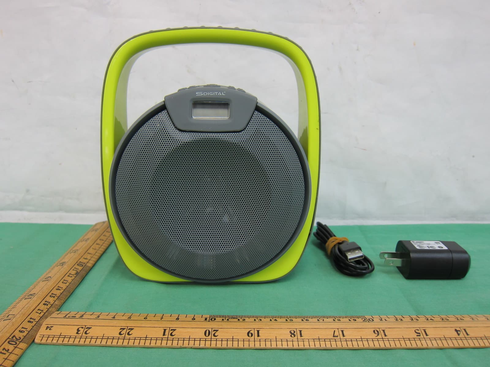
2AANA-SEM-X2808
Jul 02, 2015Portable Speaker
Equipment Class
DXX - Part 15 Low Power Communication Device Transmitter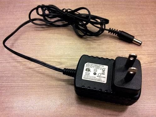
2AANA-SEM-GB3300
Mar 15, 2015Portable Speaker system
Equipment Class
DXX - Part 15 Low Power Communication Device Transmitter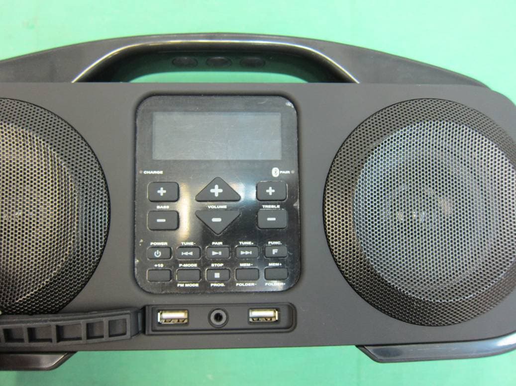
2AANA-SEM-X3808
Feb 10, 2015Portable Stereo Speaker
Equipment Class
DXX - Part 15 Low Power Communication Device Transmitter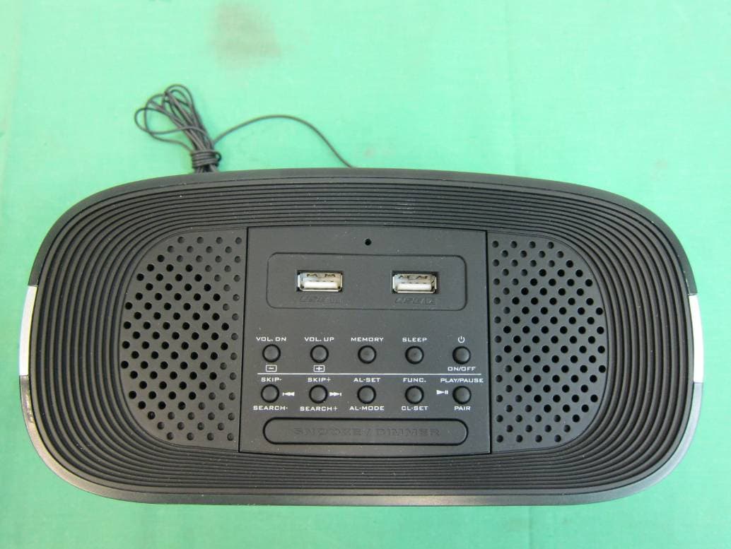
2AANA-SEM-Q7
Feb 01, 2015Clock Radio With USB Charger
Equipment Class
DXX - Part 15 Low Power Communication Device Transmitter
2AANA-SEM-GB3600
Jan 27, 2015Portable Stereo Speaker
Equipment Class
DXX - Part 15 Low Power Communication Device Transmitter