2AANL-ZB0CZigbee Module
Long Ben(Dong Guan)Elec. Tech. Co., Ltd.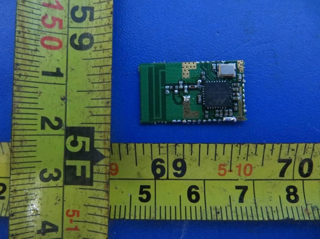
Click to zoom
Application Details
- Equipment Class
- DTS - Digital Transmission System
- Date of Grant
- Apr 28, 2014
- Application Purpose
- Original Equipment
- Date of Application
- Apr 28, 2014
- Equipment Note
- Zigbee Module
- Frequency Range
- 2405.00000000 - 2480.00000000
- Country
- China
Documents & Files
Document Text
Text extracted from the exhibit documents filed with the FCC. Open a document above to read the original.
Users Manual
Specification 1 OF 8 Long Ben(Dong Guan)Elec. Tech. Co., Ltd. Model :ZB0C Design Hewei 2014-03-12 Description : Zigbee Module Verify Wanghuanming 2014-03-12 Document No.: F20140312 Version : 1.0 Approve Wenqing 2014-03-12 Release Date: 2014-03-12 Pagination: Of 5 Specification Specification 2 OF 8 1 .Photo 2 Product Description ZB0C ZB0C is a protocol based on the latest IEEE802.15.4 Zigbee wireless communication module, compared with the Bluetooth technology, with low complexity, self-organizing, low power, low cost and so on. It is based on IEEE802.15.4 standard, can be coordinated to achieve communication between the thousands of tiny sensors that require very little energy to relay the data through radio waves from one sensor to another sensor, thus with high communication efficiency. Application ZB0C module is very wide stage to commercial building automation, home automation control (New installation) and instrument control as the focus. Commercial building can be completed automatically controlled ZB0C, administrators can effectively manage air conditioning, lighting, fire detection systems, the switch control system, to reduce energy costs, reduce management manpower saving purposes. For the consumer, if the family has installed ZB0C module system can easily monitor the overall operation of the home, effectively control Specification 3 OF 8 electricity, water, gas usage outside, they can have security features, for example, to install a wireless home sensors to monitor a variety of different situations, once the investigation into the abnormal automatically issue a warning. 3. Product Features: Low power consumption in low-power standby mode, the standby time is more than 10 times the Bluetooth communication devices Low cost, by dramatically simplifying the protocol (less than Bluetooth 1/10), reducing the requirement for communication controller, suitable for large-scale construction applications low rate, ZB0C work in the 2.4GHz band, providing about 250 kbps raw data throughput to meet the application needs of low-rate data transmission close quarters, the transmission range is generally between 10 ~ 100m, after increasing the transmission power can be increased to 1 ~ 3km. This is the distance between adjacent nodes. If the route and through the inter-node communication relay transmission distance will be farther short delay, faster response speed ZB0C, generally from sleep into working condition just 15ms, nodes are connected into the network just 30ms, further saving energy. Comparison, Bluetooth requires 3 ~ 10s, WiFi need 3 s high security, ZB0C provides three security modes, including no security settings, using access control lists (Access Control List, ACL) to prevent illegal access to data and the use of the Advanced Encryption Standard (AES 128) symmetric password to flexibly determine their security attributes. wide range of applications for home and building networks, industrial control, wireless meter reading, medical equipment, agricultural control and other occasions Specification 4 OF 8 4.Product Specification Model ZB0C Chipset 88MZ100 WIRELESS STANDARDS IEEE802.15.4 Radio Data Rate [email protected] Channel 16 WIRELESS TRANSMIT POWER(dBm) 9dBm +/-1.5 Sensitivity @PER(dBm) ≤-101 FREQUENCYRANGE 2.405~2.480GHz Interface UART 1*4PIN ANTENNA TYPE Onboard 2dBi PCB antenna Input Voltage DVDD 3.3V Max Current <35mA uA <3uA Communication Distance Indoor≥ 50m,Outdoor≥ 500m ENVIRONMENT Operating Temperature: 0°C~125°C Storage Temperature: -20°C~125°C Operating Humidity: 10%~90% non-condensing Storage Humidity: 10%~90% non-condensing Dimensions (mm) 21.2*12.3*2.0mm Specification 5 OF 8 5. pin is defined as follows: Pin number Signal assignment Signal function for lighting Pin1-2 GND Ground Pin3 GPIO12 PWM output-1(Timerl) Pin4 GPIO13 PWM output-2(Timerl) Pin5 GPIO14 SWD Clock Pin6 GPIO15 SWD Data Pin7 GPIO16 IIC SDA Pin8 VIO The IO power Pin9 GPIO17 IIC CLK Pin10 GPIO18 PWM output-3(Timerl) Pin11-13 GND Ground Pin14 GPIO21 UART2 TXD Pin15 GPIO22 UART2 TXD Pin16 GPIO23 PWM output-4(Timerl) Pin17 GND Ground Pin18 VBAT The main power Pin19 GND Ground Pin20 GPIO29 Reserve Pin21 GPIO28 Enable Pin22 GND Ground Pin23 RESET_N The reset signal Pin24 GPIO4 ADCx3 or ADCx1 and Wakeup INTx2 Pin25 GPIO5 Pin26 GPIO6 Pin27 GND Ground Specification 6 OF 8 6. FCC Statement: Federal Communication Commission Interference Statement This equipment has been tested and found to comply with the limits for a Class B digital device, pursuant to part 15 of the FCC Rules. These limits are designed to provide reasonable protection against harmful interference in a residential installation. This equipment generates, uses and can radiate radio frequency energy and, if not installed and used in accordance with the instructions, may cause harmful interference to radio communications. However, there is no guarantee that interference will not occur in a particular installation. If this equipment does cause harmful interference to radio or television reception, which can be determined by turning the equipment off and on, the user is encouraged to try to correct the interference by one or more of the following measures: • Reorient or relocate the receiving antenna. • Increase the separation between the equipment and receiver. • Connect the equipment into an outlet on a circuit different from that to which the receiver is connected. • Consult the dealer or an experienced radio/TV technician for help. FCC Caution: Any changes or modifications not expressly approved by the party responsible for compliance could void the user’s authority to operate this equipment. This device complies with part 15 of the FCC Rules. Operation is subject to the following two conditions: (1) This device may not cause harmful interference, and (2) this device must accept any interference received, including interference that may cause undesired operation. FCC Radiation Exposure Statement: “To comply with FCC RF exposure c…
Text truncated - open the document above for the full version.
Cover Letter(s)
S Long Ben(Dong Guan)Elec. Tech. Co., Ltd. Add: No.19, Jian She Road, Shi Ma Village,Tang Xia Town, Dongguan, China Tel: +86-139 2292 7321 Fax: +86-769 8781 9239 2014-04-14 To: Federal Communications Commission Authorization and Evaluation Division 7435 Oakland Mills Road Columbia, MD Confidentiality Request regarding application for certification of FCC ID: 2AANL-ZB0C We hereby request confidential treatment of information accompanying this application as outlined below: - Schematics Diagram - Block Diagram - Operation description The above materials contain trade secrets and proprietary information not customarily released to the public. The public disclosure of these materials may be harmful to the applicant and provide unjustified benefits to its competitors. The applicant understands that pursuant to Section 0.457 & 0.459 of the Rules, disclosure of this application and all accompanying documentation will not be made before the date of the Grant for this application. Sincerely, Client’s name / title : Sui Xiong Diao / General Manager Contact information / address : No.19, Jian She Road, Shi Ma Village,Tang Xia Town, Dongguan, China Tel: +86-139 2292 7321 Fax: +86-769 8781 9239 E-Mail: [email protected]
Cover Letter(s)
Applicant/Grantee Long Ben(Dong Guan)Elec. Tech. Co., Ltd. FCC ID: 2AANL-ZB0C Section 15.212 Modular Transmitters Request for Modular Approval Request for Limited Modular Approval ■ Requirements EUT Conditions Comply (Y/N) Single Modular Approval Requirements 1 The radio elements of the modular transmitter must have their own shielding. The physical crystal and tuning capacitors may be located external to the shielded radio elements. There is no shielding on the module, so this is a LMA submission. Please refer to User Manual for the restricted condition to the OEM integrator. N 2 The modular transmitter must have buffered modulation/data inputs (if such inputs are provided) to ensure that the module will comply with Part 15 requirements under conditions of excessive data rates or over-modulation. Buffered Data input stage has been integrated in chip(88MZ100). Y 3 The modular transmitter must have its own power supply regulation. DC 3.3V power supply regulated by chipset(88MZ100) Y 4 The modular transmitter must comply with the antenna and transmission system requirements of Sections 15.203, 15.204(b) and 15.204(c). The antenna must either be permanently attached or employ a “unique” antenna coupler (at all connections between the module and the antenna, including the cable). The “professional installation” provision of Section 15.203 is not applicable to modules but can apply to limited modular approvals under paragraph (b) of this section. EUT is equipped with a PCB antenna, Detail pleas reference internal photo. Y 5 The modular transmitter must be tested in a stand-alone configuration, i.e., the module must not be inside another device during testing for compliance with Part 15 requirements. Unless the transmitter module will be battery powered, it must comply with the AC line conducted requirements found in Section 15.207. AC or DC power lines and data input/output lines connected to the module must not contain ferrites, unless they will be marketed with the module (see Section 15.27(a)). The length of these lines shall be the length typical of actual use or, if that length is unknown, at least 10 centimeters to insure that there is no coupling between the case of the module and supporting Pleas reference exhibition test setup photo for the stand-alone test configuration. Y equipment. Any accessories, peripherals, or support equipment connected to the module during testing shall be unmodified and commercially available (see Section 15.31(i)). 6 The modular transmitter must be equipped with either a permanently affixed label or must be capable of electronically displaying its FCC identification number. (A) If using a permanently affixed label, the modular transmitter must be labeled with its own FCC identification number, and, if the FCC identification number is not visible when the module is installed inside another device, then the outside of the device into which the module is installed must also display a label referring to the enclosed module. This exterior label can use wording such as the following: “Contains Transmitter Module FCC ID: “2AANL-ZB0C” or “Contains FCC ID: “2AANL-ZB0C” Any similar wording that expresses the same meaning may be used. The Grantee may either provide such a label, an example of which must be included in the application for equipment authorization, or, must provide adequate instructions along with the module which explain this requirement. In the latter case, a copy of these instructions must be included in the application for equipment authorization. (B) If the modular transmitter uses an electronic display of the FCC identification number, the information must be readily accessible and visible on the modular transmitter or on the device in which it is installed. If the module is installed inside another device, then the outside of the device into which the module is installed must display a label referring to the enclosed module. This exterior label can use wording such as the following: “Contains FCC certified transmitter module(s).” Any similar wording that expresses the same meaning may be used. The user manual must include instructions on how to access the electronic display. A copy of these instructions must be included in the application for equipment authorization. The instruction on the labeling rule of the end product has been stated in the user manual of this module, please also see the exhibition label sample. Y 7 The modular transmitter must comply with any specific rules or operating requirements that ordinarily apply to a complete transmitter and the manufacturer must provide adequate instructions along with the module to explain any such requirements. A copy of these instructions must be included in the application for equipment authorization. The required FCC rule has been fulfilled and all the instruction for maintaining compliance has been clearly stated in the user manual. Y 8 The modular transmitter must comply with any applicable RF exposure requirements in its final configuration. The maximum conducted output power of this module is 10.5dBm with antenna gain 2.0dBi only, and the module is designed for end product which at least 20cm from human body as normal use. therefore this module comply with FCC §1.1310 and §2.1091 RF exposure Y A limited modular approval may be granted for single or split modular transmitters that do not comply with all of the above requirements, e.g., shielding, minimum signaling amplitude, buffered modulation/data inputs, or power supply regulation, if the manufacturer can demonstrate by alternative means in the application for equipment authorization that the modular transmitter meets all the applicable Part 15 requirements under the operating conditions in which the transmitter will be used. Limited modular approval also may be granted in those instances where compliance with RF exposure rules is demonstrated only for particular product configurations. The applicant for certification must state how cont…
Text truncated - open the document above for the full version.
External Photos
SHENZHEN LCS COMPLIANCE TESTING LABORATORY LTD. FCC ID: 2AANL-ZB0C Report No.: LCS1404080272E This report shall not be reproduced except in full, without the written approval of Shenzhen LCS Compliance Testing Laboratory Ltd.. Page 1 of 1 1. EXTERIOR PHOTOGRAPHS Fig.1 Fig.2
ID Label/Location Info
SHENZHEN LCS COMPLIANCE TESTING LABORATORY LTD FCC ID: 2AANL-ZB0C Report No.: LCS1404080272E This report shall not be reproduced except in full, without the written approval of Shenzhen LCS Compliance Testing Laboratory Ltd. Page 1 of 1 LABEL AND LOCATION Size: L1.3cm*W0.5cm Material: Tagboard Glue: adhesive sticker Font color: Black Label color: White FCC ID: 2AANL-ZB0C Label Location
Internal Photos
SHENZHEN LCS COMPLIANCE TESTING LABORATORY LTD. FCC ID: 2AANL-ZB0C Report No.: LCS1404080272E This report shall not be reproduced except in full, without the written approval of Shenzhen LCS Compliance Testing Laboratory Ltd.. Page 1 of 1 1. EXTERIOR PHOTOGRAPHS Fig.1 Fig.2
RF Exposure Info
SHENZHEN LCS COMPLIANCE TESTING LABORATORY LTD. FCC ID: 2AANL-ZB0C Report No.: LCS1404080272E ________________________________________________________________________________ _________ This report shall not be reproduced except in full, without the written approval of Shenzhen LCS Compliance Testing Laboratory Ltd.. Page 1 of 2 8. RADIO FREQUENCY EXPOSURE Limit According to §1.1310 and §2.1091 RF exposure is calculated. Table: Limits for General Population/Uncontrolled Exposure F = frequency in MHz * = Plane-wave equivalent power density Maximum Permissible Exposure The MPE was calculated at 20cm to show compliance with the power density limit. S = PG/4πR 2 S = Power density P = power input to antenna G = power gain of the antenna in the direction of interest relative to an isotropic radiator R = distance to the center of radiation of the antenna. Note: 1. Manufacturer declared that the maximum antenna gain is 2.0dBi. 2. Manufacturer declared that the nearest distance between human and the EUT is 20cm. 3. Only record worst case data. SHENZHEN LCS COMPLIANCE TESTING LABORATORY LTD. FCC ID: 2AANL-ZB0C Report No.: LCS1404080272E ________________________________________________________________________________ _________ This report shall not be reproduced except in full, without the written approval of Shenzhen LCS Compliance Testing Laboratory Ltd.. Page 2 of 2 2.4GHz Band(Zigbee) Conducted Peak output Power in dBm 9.36 dBm Max. Conducted Peak output Power in mW 8.63 mW Prediction distance 20 cm Prediction frequency 2405 MHz Antenna Gain(typical) 2.0 dBi Antenna Gain(numeric) 1.585 Power density at prediction frequency( S) 0.0027 mW/cm 2 MPE limit for uncontrolled exposure at prediction frequency 1 mW/cm 2 Test Results The power density level worst case at 20 cm is below the uncontrolled exposure limit.
Test Report
SHENZHEN LCS COMPLIANCE TESTING LABORATORY LTD. FCC ID: 2AANL-ZB0C Report No.: LCS1404080272E This report shall not be reproduced except in full, without the written approval of Shenzhen LCS Compliance Testing Laboratory Ltd.. Page 1 of 36 FCC TEST REPORT For Long Ben(Dong Guan)Elec. Tech. Co., Ltd. Zigbee Module Model No.: ZB0C Prepared for : Long Ben(Dong Guan)Elec. Tech. Co., Ltd. Address : No.19, Jian She Road, Shi Ma Village, Tang Xia Town, Dongguan, China Prepared by : Shenzhen LCS Compliance Testing Laboratory Ltd. Address : 1/F., Xingyuan Industrial Park, Tongda Road, Bao'an Avenue, Bao'an District, Shenzhen, Guangdong, China Date of receipt of test sample : April 08, 2014 Number of tested samples : 1 Serial number : Prototype Date of Test : April 08, 2014 - April 14, 2014 Date of Report : April 14, 2014 SHENZHEN LCS COMPLIANCE TESTING LABORATORY LTD. FCC ID: 2AANL-ZB0C Report No.: LCS1404080272E This report shall not be reproduced except in full, without the written approval of Shenzhen LCS Compliance Testing Laboratory Ltd.. Page 2 of 36 FCC TEST REPORT FCC CFR 47 PART 15 C(15.247): 2013 Report Reference No. .............. : LCS1404080272E Date of Issue ................................ : April 14, 2014 Testing Laboratory Name ......... : Shenzhen LCS Compliance Testing Laboratory Ltd. Address ........................................ : 1/F., Xingyuan Industrial Park, Tongda Road, Bao'an Avenue, Bao'an District, Shenzhen, Guangdong, China Testing Location/ Procedure ........ : Full application of Harmonised standards ■ Partial application of Harmonised standards □ Other standard testing method □ Applicant’s Name ....................... : Long Ben(Dong Guan)Elec. Tech. Co., Ltd. Address ........................................ : No.19, Jian She Road, Shi Ma Village, Tang Xia Town, Dongguan, China Test Specification Standard ....................................... : FCC CFR 47 PART 15 C(15.247): 2013 Test Report Form No. ................ : LCSEMC-1.0 TRF Originator ............................ : Shenzhen LCS Compliance Testing Laboratory Ltd. Master TRF .................................. : Dated 2011-03 Shenzhen LCS Compliance Testing Laboratory Ltd. All rights reserved. This publication may be reproduced in whole or in part for non-commercial purposes as long as the Shenzhen LCS Compliance Testing Laboratory Ltd. is acknowledged as copyright owner and source of the material. Shenzhen LCS Compliance Testing Laboratory Ltd. takes no responsibility for and will not assume liability for damages resulting from the reader's interpretation of the reproduced material due to its placement and context. Test Item Description. ............... : Zigbee Module Trade Mark .................................. : N/A Model/ Type reference ................. : ZB0C Ratings ......................................... : DC 3.3V Result ......................................... : Positive Compiled by: Supervised by: Approved by: Leo Lee/ File administrators Fox Zhang/ Technique principal Gavin Liang/ Manager SHENZHEN LCS COMPLIANCE TESTING LABORATORY LTD. FCC ID: 2AANL-ZB0C Report No.: LCS1404080272E This report shall not be reproduced except in full, without the written approval of Shenzhen LCS Compliance Testing Laboratory Ltd.. Page 3 of 36 FCC -- TEST REPORT Test Result Positive The test report merely corresponds to the test sample. It is not permitted to copy extracts of these test result without the written permission of the test laboratory. Test Report No. : LCS1404080272E April 14, 2014 Date of issue Type / Model........................... : ZB0C EUT......................................... : Zigbee Module Applicant............................... : Long Ben(Dong Guan)Elec. Tech. Co., Ltd. Address.................................. : No.19, Jian She Road, Shi Ma Village, Tang Xia Town, Dongguan, China Telephone............................... : / Fax.......................................... : / Manufacturer........................ : Long Ben(Dong Guan)Elec. Tech. Co., Ltd. Address................................... : No.19, Jian She Road, Shi Ma Village, Tang Xia Town, Dongguan, China Telephone............................... : / Fax.......................................... : / Factory................................... : Long Ben(Dong Guan)Elec. Tech. Co., Ltd. Address................................... : No.19, Jian She Road, Shi Ma Village, Tang Xia Town, Dongguan, China Telephone............................... : / Fax.......................................... : / SHENZHEN LCS COMPLIANCE TESTING LABORATORY LTD. FCC ID: 2AANL-ZB0C Report No.: LCS1404080272E This report shall not be reproduced except in full, without the written approval of Shenzhen LCS Compliance Testing Laboratory Ltd.. Page 4 of 36 TABLE OF CONTENTS Description ..................................................................................................................... Page 1. GENERAL INFORMATION ............................................................................................................................................ 5 1.1. DESCRIPTION OF DEVICE (EUT) ..................................................................................................................................... 5 1.2. HOST SYSTEM CONFIGURATION LIST AND DETAILS ....................................................................................................... 5 1.3. EXTERNAL I/O ................................................................................................................................................................ 5 1.4. DESCRIPTION OF TEST FACILITY ..................................................................................................................................... 6 1.5. STATEMENT OF THE MEASUREMENT UNCERTAINTY ...................................................................................................... 6 1.6. MEASUREMENT UNCERTAINTY ..................................................…
Text truncated - open the document above for the full version.
Test Setup Photos
SHENZHEN LCS COMPLIANCE TESTING LABORATORY LTD. FCC ID: 2AANL-ZB0C Report No.: LCS1404080272E _______________________________________________________________________________________________ This report shall not be reproduced except in full, without the written approval of Shenzhen LCS Compliance Testing Laboratory Ltd.. Page 1 of 2 1. TEST SETUP PHOTOGRAPHS 1.1. Photo of Radiated Emissions Measurement (X Position) Fig.1 Fig.2 SHENZHEN LCS COMPLIANCE TESTING LABORATORY LTD. FCC ID: 2AANL-ZB0C Report No.: LCS1404080272E _______________________________________________________________________________________________ This report shall not be reproduced except in full, without the written approval of Shenzhen LCS Compliance Testing Laboratory Ltd.. Page 2 of 2 Fig.2 1.2. Photo of Line Conducted Emissions Measurement
Contact Information
Applicant
Sui Xiong Diao(General Manager)
Test Firm
Shenzhen LCS Compliance Testing Laboratory Ltd.Gavin Liang
Technical Specifications
| # | Rule Parts | Frequency Range | Power Output |
|---|---|---|---|
| 1 | 15C | 2.40 GHz - 2.48 GHz | 8.63 mW |
Other Applications from Long Ben(Dong Guan)Elec. Tech. Co., Ltd.
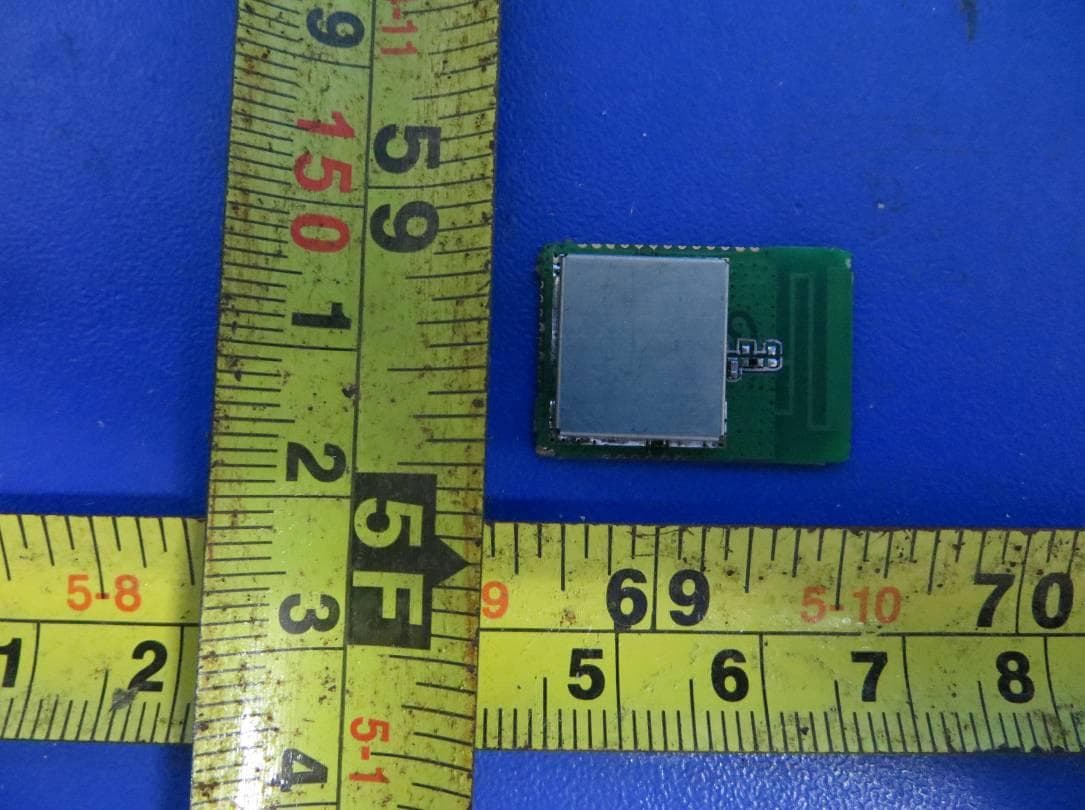
2AANL-ZB0C01
Jun 19, 2014ZigBee Module
Equipment Class
DTS - Digital Transmission System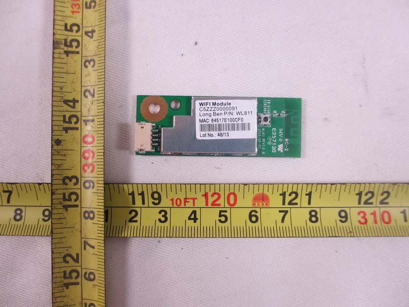
2AANL-WL811
Dec 18, 2013WIFI Module
Equipment Class
DTS - Digital Transmission System2AANL-WL91
Aug 21, 2013WIFI Module
Equipment Class
DTS - Digital Transmission System