2AANZBSSELECTRIC FOLDING SCOOTER
DGL Group LTD.
Click to zoom
Application Details
- Equipment Class
- DTS - Digital Transmission System
- Date of Grant
- Nov 21, 2022
- Application Purpose
- Original Equipment
- Date of Application
- Nov 21, 2022
- Equipment Note
- ELECTRIC FOLDING SCOOTER
- Frequency Range
- 2402.00000000 - 2480.00000000
- Company
- DGL Group LTD.
- Country
- United States
Documents & Files
Document Text
Text extracted from the exhibit documents filed with the FCC. Open a document above to read the original.
Users Manual
DGL Group 2045 Lincoln Highway Edison, NJ 08817 [email protected] | hover-1.com BOSS Owner’s Manual Assembly & Maintenance 02 HOVER 1 PRO SERIES DGL Group 2045 Lincoln Highway Edison, NJ 08817, United States hover1rideables hover-1 ridehover1 hover1rideables @ridehover1 @ridehover1 Join our Hover 1 Community of riders wherever you are! [email protected] 866.831.1520 www.hover-1.com Thank you for choosing the Hover-1 Boss. It is our pleasure to guide you through setting up your Boss and hitting the road! Please read through this Owner’s Manual to get familiar with the proper operation of your Boss E-Scooter’s controls, features, capabilities, and limitations. This manual will be your guide for general maintenance, safety precautions, assembly, and servicing of the unit. Before riding your Boss E-Scooter, be sure all the parts are properly torqued, tightened, and connected (particularly the parts that had to be manually installed). Remember to always use your best judgment and obey all traffic laws. Additional instructions and media will be available to assist you with repairs or maintenance of your Hover-1 Pro Series E-Scooter. 02 01 CONTENTS 05. BASICS Diagram of the Boss General Symbols Safety Advice 13. ASSEMBLY & PARTS 09. SAFETY PRECAUTIONS Setting Up Your E Scooter 25. OPERATIONS Before Riding Pre-Ride Checklist Speed Modes Cruise Control Kick to Start Riding Your Boss E Scooter Operating Your Device Speed & Weight Limitations Operating Range Hover-1 E Mobility App LED Display Error Codes 05 07 07 15 Safety Precautions19 25 26 26 27 27 27 27 28 28 30 31 32 33. MAINTENANCE Battery Speci ications Battery Maintenance Charging Your Boss Speci ications 34 34 36 37 17. SAFETY CHECKLIST 38. FCC STATEMENT 39. WARRANTY 0304 DIAGRAM OF THE BOSS Brake Lever (R) Headlight Rear Fender BASICS01 Taillight Disc BrakeMotor Folding Hinge Front ShocksKickstand Foot Deck Folding Hook LED DisplayHandlebar Brake Lever/Bell (L) Thumb Throttle 0506 GENERAL SYMBOLS SAFETY ADVICE WARNING WARNING NOTICE DANGER Recommendations and meaningful additional information. Warns about a situation that can cause death, serious physical injury and/or heavy material damage if safety instructions are ignored. Possible dangers to your life and health if respective calls to action are ignored. Please adhere to the following safety instructions while operating your Boss: INSTRUCTIONS PERTAINING TO RISK OF FIRE OR ELECTRIC SHOCK - IMPORTANT SAFETY INSTRUCTIONS WARNING - When using this product, basic precautions should always be followed, including the following: Read all the instructions before using the product. To reduce the risk of injury, close supervision is necessary when the product is used near children. Do not put fingers or hands into the product. Do not use this product if the flexible power cord or output cable is frayed, has broken insulation, or any other signs of damage. This equipment is not intended to be used at ambient temperatures less than 0°C (32°F) or above ambient temperatures of 30°C (86°F). The battery is intended to be charged when the ambient temperature is between 0°C (32°F) and 30°C (86°F). Never charge the battery when ambient temperatures are outside this range. Modifying or attempting to repair the E-Scooter system except as indicated in the instructions for use and care is prohibited. Charging of the E-Scooter shall only be performed with the manufacturer's recommended charger. SAVE THESE INSTRUCTIONS Always wear a properly fitted helmet and protective gear while riding. See and be seen. Wear reflective clothing while riding at night. Learn the rules of the road before riding. Obey all traffic laws. Make sure handlebar grips are not damaged and are properly installed. Always check brakes before riding. Check for traffic. Always be aware of the traffic around you. Watch for and avoid road hazards. Reduce speed when riding on wet terrain. To prevent skidding or potential injuries, do not accelerate or brake suddenly while making turns. To avoid water damage, do not leave your E-Scooter in inclement weather. When activating pedal assist, increase speed slowly to avoid injury. Do not use and/or leave the charger outdoors in hot or wet weather conditions. Do not ride up or down extremely steep inclines. Do not touch the body of the motor immediately after riding, as the surface may be hot. Do not make any aftermarket modifications to your Boss that are not expressly approved by Hover-1 Pro Series. Do not ride the E-Scooter if you exceed the maximum weight limit of 264 lbs . • • • • • • • • • • • • • • • • 0708 SAFETY PRECAUTIONS02 ATTENTION 1. Use only the supplied charger from Hover-1 with this E-Scooter. 2. The operating temperature range of the charger is 32°F - 86°F (0°C - 30°C). 3. The operating temperature range of the Boss is 32°F - 86°F (0°C - 30°C). 4. Do not ride on icy or slippery surfaces. 5. Read the operation manual and warning labels before riding. 6. Store the Boss in a dry, ventilated environment. 7. When transporting the Boss, avoid violent crashes or impact. LOW TEMPERATURE WARNING Low temperatures will affect the lubrication of moving parts inside the Boss, increasing internal resistance. Additonally, the discharge capacity and capacity of the battery will be significantly decreased. Use caution when riding the Boss in cold temperatures (below 40°F/4°C). Doing so may increase the risk of mechanical failures of the E-Scooter, which may lead to damage to your device, property damage, serious bodily injury, and even death. SAFETY INSTRUCTIONS Keep the E-Scooter away from heat sources, direct sunlight, humidity, water, and any other liquids. Do not operate the E-Scooter if it has been exposed to water, moisture, or any other liquids to prevent electric shock, explosion, and/or injury to yourself and damage to the E-Scooter. Do not use the E-Scooter if it has been dropped or damaged in any way. Repairs to electrical equipment should only be performed by the manufacturer. Improp…
Text truncated - open the document above for the full version.
Cover Letter(s)
DGL Group,Ltd. Agent Authorization Company: DGL Group,Ltd. Address: 2045 Lincoln Highway, 3rd Floor, Edison, NJ 08817, United States Product Name: ELECTRIC FOLDING SCOOTER Model Number(s): H1-BSS-BLK, H1-BSS-BLU, H1-BSS-WHT, H1-BSS-ORG Product Description: ELECTRIC FOLDING SCOOTER We authorize MiCOM Labs Inc., 575 Boulder Court, Pleasanton, California 94566, USA, to act on our behalf on all matters concerning the certification of above named equipment. We declare that MiCOM Labs Inc. is allowed to forward all information related to the approval and certification of equipment to the regulatory agencies as required and to discuss any issues concerning the approval application. Any and all acts carried out by MiCOM Labs on our behalf shall have the same effect as acts of our own. Signature: Date: 2022-11-18 Name: Amy Chao Company: DGL Group,Ltd.
Cover Letter(s)
DGL Group LTD. Nov.18, 2022 Office of Engineering Technology Federal Communications Commission 7435 Oakland Mills Road Columbia, MD 21046 USA Subject: Explanation of differences between product types FCC ID : 2AANZBSS Model Number: H1-BSS-BLK, H1-BSS-BLU, H1-BSS-WHT, H1-BSS-ORG To Whom It May Concern: We, The DGL Group LTD. hereby declare that the models are identical except the appearance of the color . Except for the different above, no other modification is performed. Sincerely, Signature: DGL Group LTD. Contact person: Amy Chao
Cover Letter(s)
DGL Group LTD. Office of Engineering Technology Federal Communications Commission 7435 Oakland Mills Road Columbia, MD 21046 USA Date: 2022-11-17 Subject; Request for Confidentiality FCC ID: 2AANZBSS To Whom It May Concern, Pursuant to the provisions of the Commission’s rules Title 47 Sections §0.457 and §0.459, we are requesting the Commission to withhold the following attachment(s) as confidential documents from public disclosure indefinitely. These documents contain detailed system and equipment descriptions and are considered as proprietary information in operation of the equipment. The public disclosure of these documents might be harmful to our company and would give competitors an unfair advantage in the market. Schematic Diagram Block Diagram Parts List Operational Description Tune-up Procedure In additional to above mentioned documents, in order to comply with the marketing regulations in Title 47 CFR §2.803 and the importation rules in Title 47 CFR §2.1204, while ensuring that business sensitive information remains confidential until the actual marketing of newly authorized devices, we request Short Term Confidentiality of the following attachment(s); External Photos Test Setup Photos Internal Photos User Manual For 45 days, pursuant to Public Notice DA 04-1705. OR For 180 days pursuant to KDB 726920 D01. It is our understanding that all measurement test reports, FCC ID label format and correspondence during the certification review process cannot be granted as confidential documents and this information will be available for public review once the grant of equipment authorization is issued. Sincerely DGL Group LTD. Contact person: Amy Chao
External Photos
Report No.: AGC01559221005AP02 Page 1 of 4 EXTERNAL PHOTOS All VIEW OF EUT TOP VIEW OF EUT Report No.: AGC01559221005AP02 Page 2 of 4 BOTTOM VIEW OF EUT FRONT VIEW OF EUT Report No.: AGC01559221005AP02 Page 3 of 4 BACK VIEW OF EUT LEFT VIEW OF EUT Report No.: AGC01559221005AP02 Page 4 of 4 RIGHT VIEW OF EUT ****************************************End of Report****************************************
Internal Photos
Report No.: AGC01559221005AP02 Page 1 of 5 INTERNAL PHOTOS OPEN VIEW OF EUT (FIGURE 1) VIEW OF BATTERY Report No.: AGC01559221005AP02 Page 2 of 5 ANTENNA CLOSE-UP PHOTO-1 INTERNAL VIEW OF EUT (FIGURE 1) Antenna Report No.: AGC01559221005AP02 Page 3 of 5 INTERNAL VIEW OF EUT (FIGURE 2) INTERNAL VIEW OF EUT (FIGURE 3) Report No.: AGC01559221005AP02 Page 4 of 5 INTERNAL VIEW OF EUT (FIGURE 4) INTERNAL VIEW OF EUT (FIGURE 5) Report No.: AGC01559221005AP02 Page 5 of 5 BATTERY VIEW OF EUT ADAPTER VIEW OF EUT ****************************************End of Report****************************************
RF Exposure Info
RF EXPOSURE EVALUATION 1. PRODUCT INFORMATION Product Description ELECTRIC FOLDING SCOOTER Test Model H1-BSS-BLK FCC ID 2AANZBSS 2. EVALUATION METHOD According to 447498 D01 General RF Exposure Guidance v06 The 1-g and 10-g SAR test exclusion thresholds for 100 MHz to 6 GHz at test separation distances ≤ 50 mm are determined by: [(max. power of channel, including tune-up tolerance, mW)/(min. test separation distance, mm)] ·[√f(GHz)] ≤ 3.0 for 1-g SAR and ≤ 7.5 for 10-g extremity SAR. Where f(GHz) is the RF channel transmit frequency in GHz Power and distance are rounded to the nearest mW and mm before calculation 3. CALCULATION BLE: Pt=-0.913dBm=0.81mW The value of the Maximum output power Pt is referred to the test report of the CFR47 §15.247. The result for RF exposure evaluation SAR=(0.81mW /5mm) .[√2.402(GHz)]= 0.25<3.0 for 1-g SAR and ≤ 7.5 for 10-g extremity SAR. 4. CONCLUSION The SAR evaluation is not required.
Test Report
Page 1 SHANGHAI DEMAN INFORMATION TECHNOLOGY CO.,LTD. CUSTOMER NAME: PRODUCT NAME: Ren Feng P/N: WRITED: DATE: AVERSIONS: TUYA 20191020 BT7L PCB Antenna BT Module Page 2 Measurement data Frequency (MHz) 240024502500 Return Loss-8.73-11.76-11.21 VSWR 2.161.711.77 Page 3 Radiation pattern Z Y X Page 4 Directivity Diagram Z Y X XY YZ XZ 2D Page 5 © 2011, Deman Electronics 3D Page 6 Freq.(MHz)Effi(%)Gain (dBi) 2400 52.29 1.62 2410 52.17 1.71 2420 53.14 1.93 2430 54.16 1.98 2440 57.62 2.00 2450 59.64 2.17 2460 61.55 2.45 2470 60.64 2.38 2480 62.86 2.54 2490 59.85 2.30 2500 60.41 2.49 Efficiency&Gain
Test Report
Page 1 of 42 FCC Test Report Report No.: AGC01559221005FE02 FCC ID : 2AANZBSS APPLICATION PURPOSE : Original Equipment PRODUCT DESIGNATION : ELECTRIC FOLDING SCOOTER BRAND NAME : HOVER-1 MODEL NAME : H1-BSS-BLK, H1-BSS-BLU, H1-BSS-WHT, H1-BSS-ORG APPLICANT : DGL Group LTD. DATE OF ISSUE : Nov. 16, 2022 STANDARD(S) : FCC Part 15.247 REPORT VERSION : V1.0 Attestation of Global Compliance (Shenzhen) Co., Ltd Report No.: AGC01559221005FE02 Page 2 of 42 REPORT REVISE RECORD Report Version Revise Time Issued Date Valid Version Notes V1.0 / Nov. 16, 2022 Valid Initial Release Report No.: AGC01559221005FE02 Page 3 of 42 TABLE OF CONTENTS 1. VERIFICATION OF COMPLIANCE .................................................................................................................. 5 2. GENERAL INFORMATION .............................................................................................................................. 6 2.1. PRODUCT DESCRIPTION ........................................................................................................................ 6 2.2. TABLE OF CARRIER FREQUENCYS ....................................................................................................... 6 2.3. RELATED SUBMITTAL(S)/GRANT(S) ....................................................................................................... 7 2.4. TEST METHODOLOGY ............................................................................................................................. 7 2.5. SPECIAL ACCESSORIES .......................................................................................................................... 7 2.6. EQUIPMENT MODIFICATIONS ................................................................................................................. 7 2.7. ANTENNA REQUIREMENT ....................................................................................................................... 7 3. MEASUREMENT UNCERTAINTY ................................................................................................................... 8 4. DESCRIPTION OF TEST MODES ................................................................................................................... 9 5. SYSTEM TEST CONFIGURATION ................................................................................................................ 10 5.1. CONFIGURATION OF TESTED SYSTEM ............................................................................................... 10 5.2. EQUIPMENT USED IN TESTED SYSTEM .............................................................................................. 10 5.3. SUMMARY OF TEST RESULTS .............................................................................................................. 10 6. TEST FACILITY .............................................................................................................................................. 11 7. PEAK OUTPUT POWER ................................................................................................................................ 12 7.1. MEASUREMENT PROCEDURE .............................................................................................................. 12 7.2. TEST SET-UP (BLOCK DIAGRAM OF CONFIGURATION) .................................................................... 12 7.3. LIMITS AND MEASUREMENT RESULT .................................................................................................. 13 8. BANDWIDTH .................................................................................................................................................. 15 8.1. MEASUREMENT PROCEDURE .............................................................................................................. 15 8.2. TEST SET-UP (BLOCK DIAGRAM OF CONFIGURATION) .................................................................... 15 8.3. LIMITS AND MEASUREMENT RESULTS ............................................................................................... 15 9. CONDUCTED SPURIOUS EMISSION........................................................................................................... 19 9.1. MEASUREMENT PROCEDURE .............................................................................................................. 19 9.2. TEST SET-UP (BLOCK DIAGRAM OF CONFIGURATION) .................................................................... 19 9.3. MEASUREMENT EQUIPMENT USED .................................................................................................... 19 9.4. LIMITS AND MEASUREMENT RESULT .................................................................................................. 19 10. MAXIMUM CONDUCTED OUTPUT POWER SPECTRAL DENSITY ........................................................ 26 Report No.: AGC01559221005FE02 Page 4 of 42 10.1. MEASUREMENT PROCEDURE ............................................................................................................ 26 10.2. TEST SET-UP (BLOCK DIAGRAM OF CONFIGURATION) .................................................................. 26 10.3. MEASUREMENT EQUIPMENT USED .................................................................................................. 26 10.4. LIMITS AND MEASUREMENT RESULT................................................................................................ 26 11. RADIATED EMISSION ................................................................................................................................. 28 11.1. MEASUREMENT PROCEDURE ............................................................................................................ 28 11.2. TEST SETUP .......................................................................................................................................... 29 11.3. LIMITS AND MEASUREMENT RESULT...............................................................…
Text truncated - open the document above for the full version.
Test Setup Photos
Report No.: AGC01559221005AP01 Page 1 of 2 TEST SETUP PHOTOS RADIATED EMISSION TEST SETUP BELOW 1GHz RADIATED EMISSION TEST SETUP ABOVE 1GHz Report No.: AGC01559221005AP01 Page 2 of 2 AC POWER LINE CONDUCTED TEST SETUP RF CONDUCTED TEST SETUP ****************************************End of Report*************************************
Contact Information
Applicant
Amy Chao
Technical Contact
Test Firm
Attestation of Global Compliance (Shenzhen) Co., LDoris Li
[email protected]+86-755-25234088
Technical Specifications
| # | Rule Parts | Frequency Range | Power Output |
|---|---|---|---|
| 1 | 15C | 2.40 GHz - 2.48 GHz | 800.00 µW |
Other Applications from DGL Group LTD.
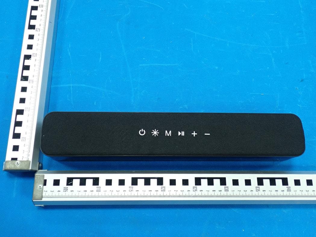
2AANZ-HYLSOBBLK
Jan 28, 2026LED Speaker Bar
Equipment Class
DSS - Part 15 Spread Spectrum Transmitter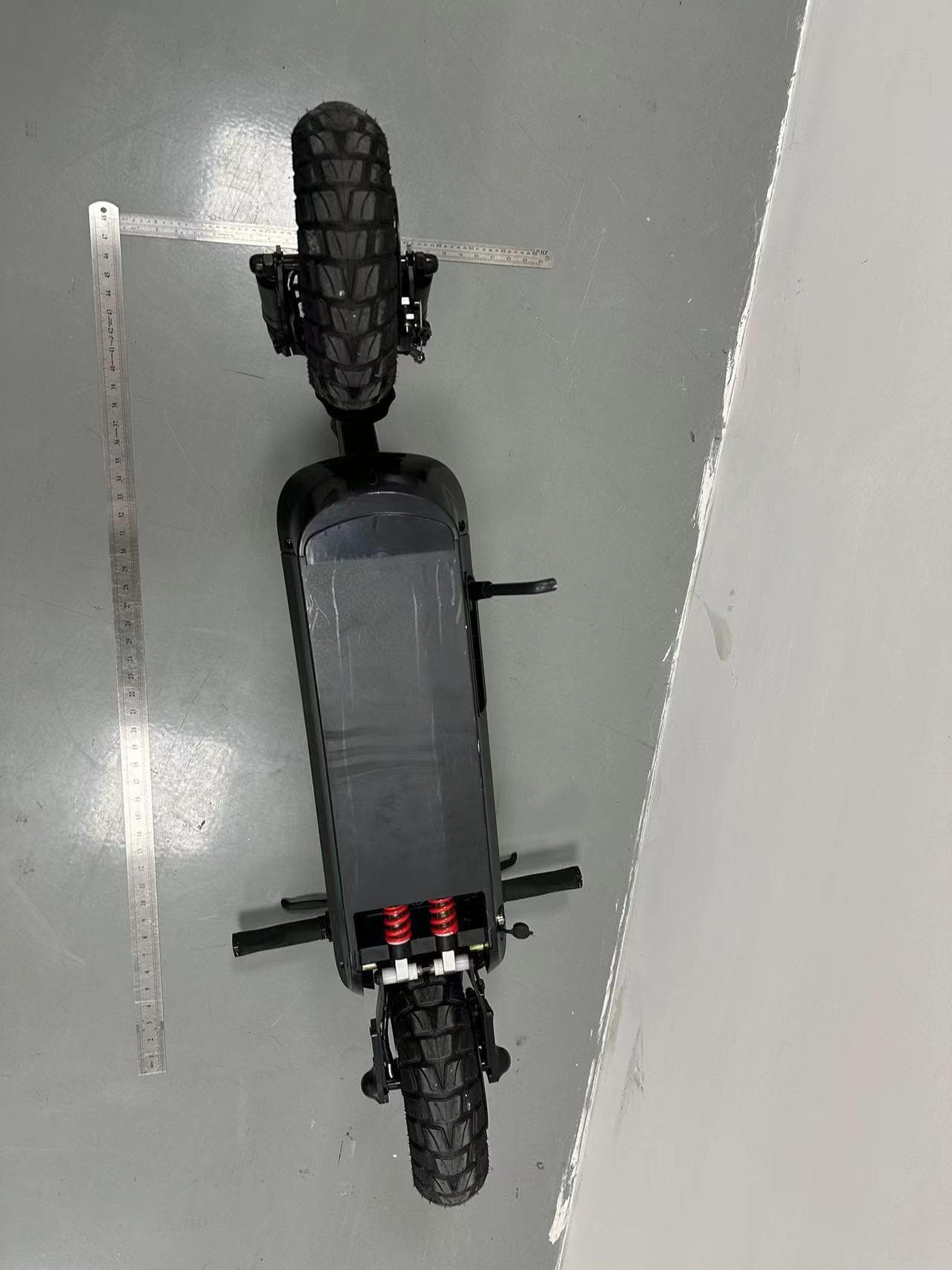
2AANZBSSDM
Oct 14, 2024HOVER-1 PRO SERIES
Equipment Class
DTS - Digital Transmission System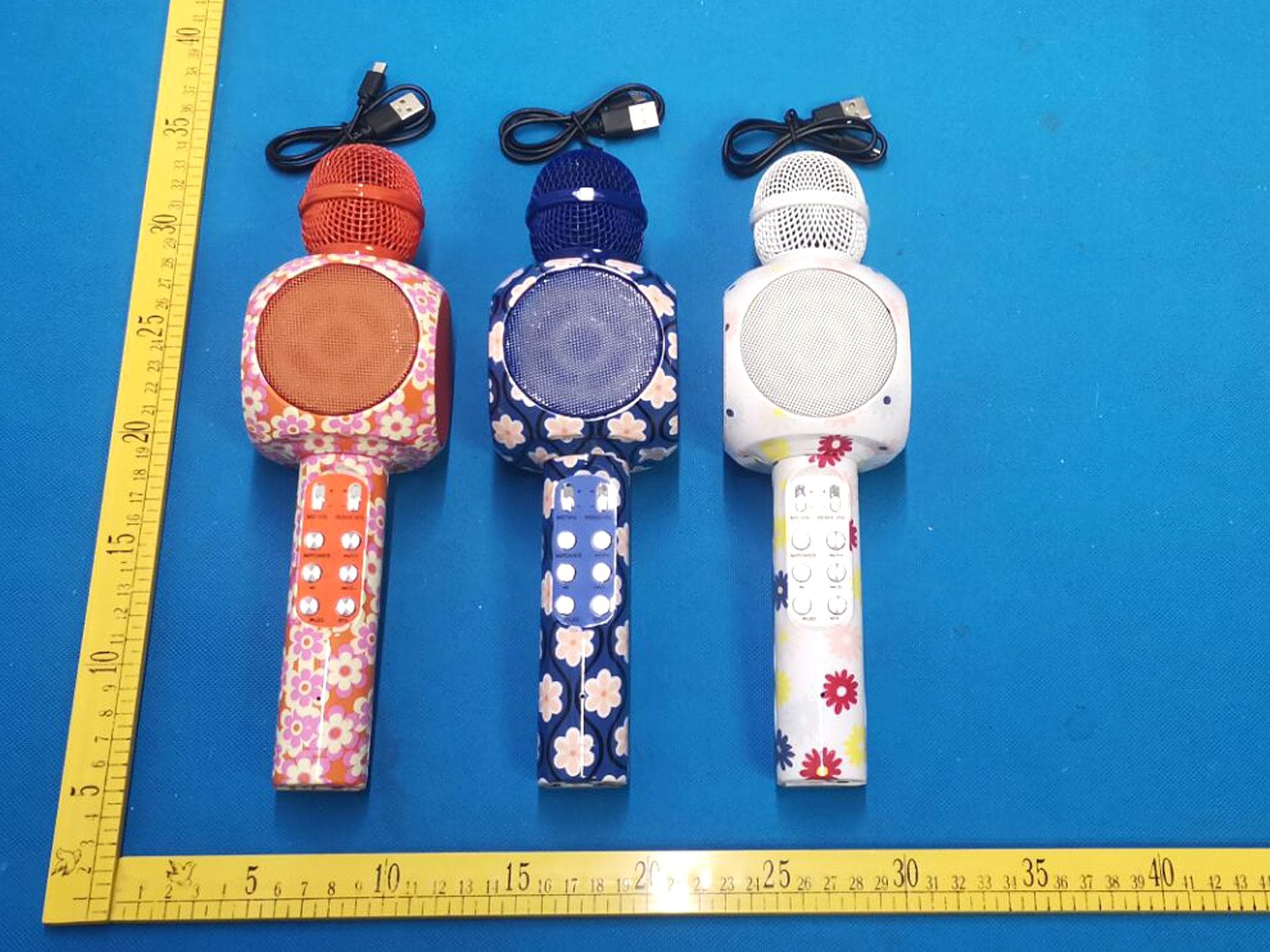
2AANZKRKFLR
Oct 10, 2024Light up Karaoke Mic with Built-in Wireless Speaker
Equipment Class
DTS - Digital Transmission System
2AANZPXLS2
Sep 26, 2024LED Pixie Light Strip
Equipment Class
DTS - Digital Transmission System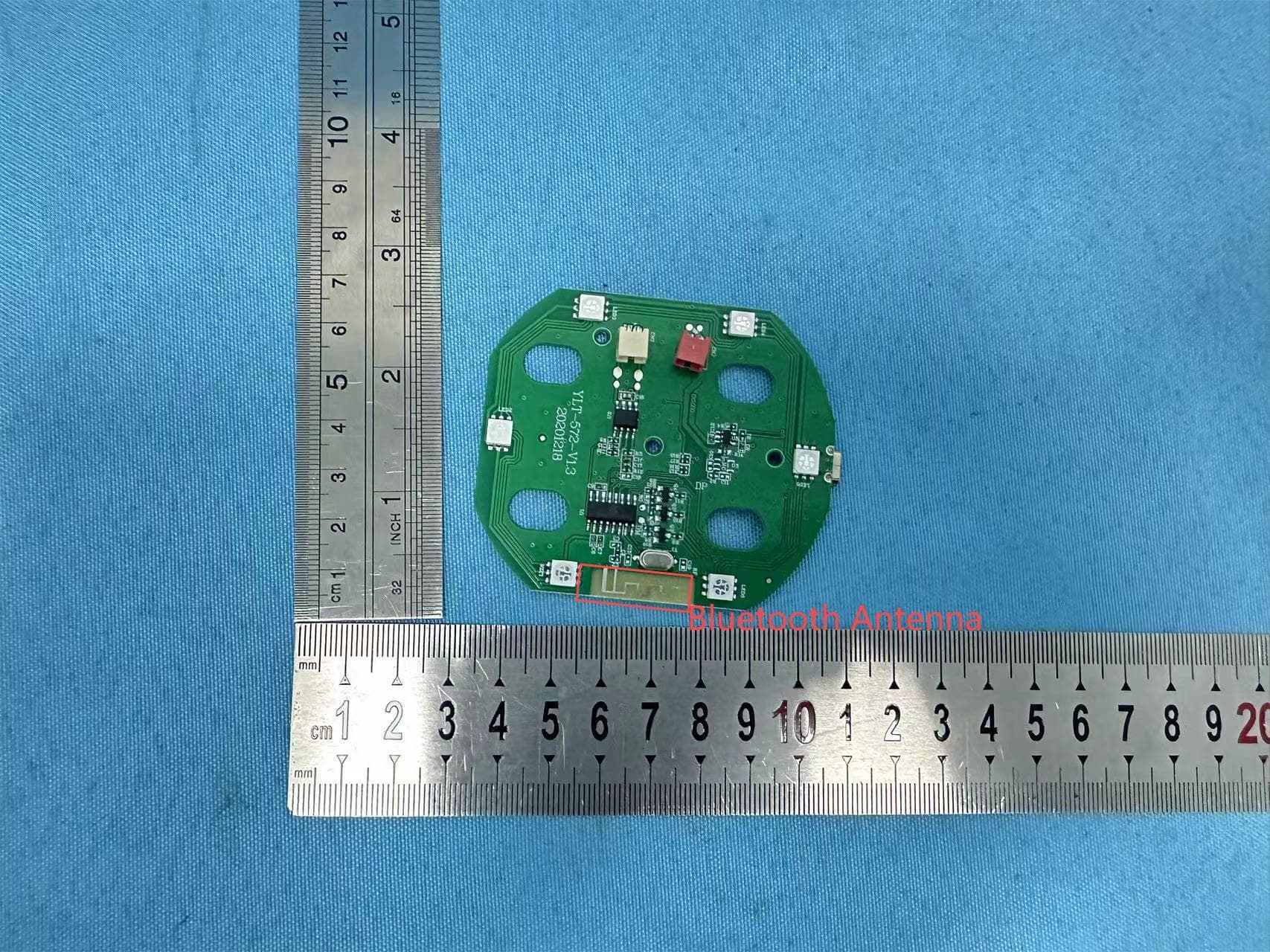
2AANZFLED1
Aug 06, 2024WIRELESS LED SPEAKER
Equipment Class
DSS - Part 15 Spread Spectrum Transmitter