2AANZIDLHOVER-1 EDGE - FOLDING ELECTRIC SCOOTER - MODULE
DGL Group LTD.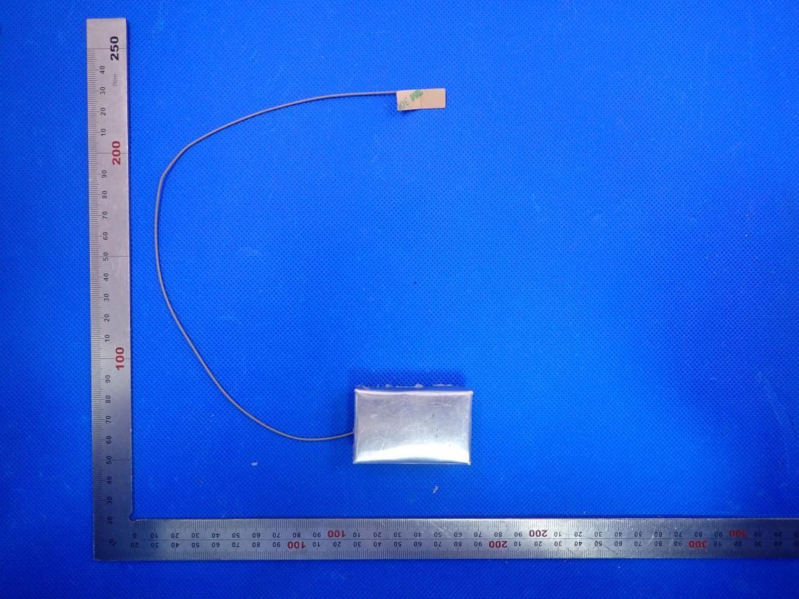
Click to zoom
Application Details
- Equipment Class
- DSS - Part 15 Spread Spectrum Transmitter
- Date of Grant
- Aug 03, 2020
- Application Purpose
- Original Equipment
- Date of Application
- Aug 03, 2020
- Equipment Note
- HOVER-1 EDGE - FOLDING ELECTRIC SCOOTER - MODULE
- Frequency Range
- 2402.00000000 - 2480.00000000
- Company
- DGL Group LTD.
- Country
- United States
Documents & Files
Document Text
Text extracted from the exhibit documents filed with the FCC. Open a document above to read the original.
Users Manual
816Bluetooth Module Manual 1,The power supply voltage of bluetooth module is 12V-80V, with 3.3V enabling foot switch, enabling switching voltage is 3V-5V, audio output is differential output, and the output power is 4EURO 3W. 2. Job Description: Bluetooth module is powered on, the controller outputs high level to a 3.3 V can make feet, can make the feet to 12 p10 the MOS conduction, the whole module which begin to work, after the success of the bluetooth connected with mobile phone via bluetooth pass bluetooth chip, the audio audio signal to the bluetooth chip output difference HT6872 amplifiers, audio after amplification push 4 r3w trumpet playing out. 3,(OEM) Integrator has to assure compliance of the entire end-product incl. the integrated RF Module. For 15 B (§15.107 and if applicable §15.107) compliance, the host manufacturer is required to show compliance with 15 while the module is installed and operating. Furthermore the module should be transmitting and the evaluation should confirm that the module's intentional emissions (15C) are compliant (fundamental / out-of-band). Finally the integrator has to apply the appropriate equipment authorization (e.g. Verification) for the new host device per definition in §15.101. Integrator is reminded to assure that these installation instructions will not be made available to the end - user of the final host device. The final host device, into which this RF Module isintegrated" hasto be labelled with an auxilliary lable stating the FCC IDofthe RF Module, such as "Contains FCC ID:2AANZIDL "This device complies with part 15 of the FCC rules. Operation is subject to the following two conditions: (1)this devicemay not cause harmful interference, and (2)this devicemust accept any interference received, including interference thatmay cause undesired operation." NOTE: This equipment has been tested and found to comply with the limits for a Class B digital device, pursuant to part 15 of the FCC Rules. These limits are designed to provide reasonable protection against harmful interference in a residential installation. This equipment generates, uses and can radiate radio frequency energy and, if not installed and used in accordance with the instructions, may cause harmful interference to radio communications. However, there is no guarantee that interference will not occur in a particular installation. If this equipment does cause harmful interference to radio or television reception, which can be determined by turning the equipment off and on, the user is encouraged to try to correct the interference by one or more of the following measures: --Reorient or relocate the receiving antenna. --Increase the separation between the equipment and receiver. --Connect the equipment into an outlet on a circuit different from that to which the receiver is connected. --Consult the dealer or an experienced radio/TV technician for help. Changes or modifications to this unit not expressly approved by the party responsible for compliance could void the user's authority to operate the equipment. Module statement The single-modular transmitter is a self-contained, physically delineated, component for which compliance can be demonstrated independent of the host operating conditions, and which complies with all eight requirements of § 15.212(a)(1) as summarized below. 1) The radio elements have the radio frequency circuitry shielded. 2) The module has buffered modulation/data inputs to ensure that the device will comply with Part 15 requirements with any type of input signal. 3) The module contains power supply regulation on the module. 4) The module contains a permanently attached antenna. 5) The module demonstrates compliance in a stand-alone configuration. 6) The module is labeled with its permanently affixed FCC ID label 7) The module complies with all specific rules applicable to the transmitter, including all the conditions provided in the integration instructions by the grantee. 8) The module complies with RF exposure requirements. This transmitter/module must not be collocated or operating in conjunction with any other antenna or transmitter. Integration instructions for host product manufacturers according to 816 Manual v01 2.2 List of applicable FCC rules FCC Part 15.247 2.3 Specific operational use conditions This transmitter/module and its antenna(s) must not be co-located or operating in conjunction with any other antenna or transmitter. This information also extends to the host manufacturer’s instruction manual. 2.4 Limited module procedures not applicable 2.5 Trace antenna designs It is “not applicable” as trace antenna which is not used on the module. 2.6 RF exposure considerations This equipment complies with FCC RF radiation exposure limits set forth for an uncontrolled environment. This compliance to FCC radiation exposure limits for an uncontrolled environment, and minimum of 5mm separation between antenna and body. The host product manufacturer would provide the above information to end users in their end-product manuals. 2.7 Antennas The module equipped with PCB Antenna(-0.318dBi, 2.402 GHz to 2.480GHz) 2.8 Label and compliance information The end product must carry a physical label or shall use e-labeling followed KDB784748D01 and KDB 784748 stating “Contains Transmitter Module FCC ID: 2AANZIDL”. 2.9 Information on test modes and additional testing requirements Information on test modes: The host manufacturer can use software for access to the test modes. Connected to the device through the serial port of the host product and control the module. If it does not work, then the host product manufacturer should coordinate with the module manufacturer for access to test mode software. The following provides guidance to host product when installing this module on how they may verify the end product: A. If the modular transmitter has been fully tested by the module grantee on the required number of channels, modulation types, and modes, it should not be nec…
Text truncated - open the document above for the full version.
Cover Letter(s)
RE FCC ID: 2AANZIDL To the certification reviewer: We are hereby applying for full modular approval of the above-referenced FCC ID, based on compliance with all of the criteria as detailed below. Sincerely, Josephine Tran Part 15 Unlicensed Single Modular Transmitter Approval Justification per 15.212 Requirement per 15.212 reference (i) The radio elements of the modular transmitter must have their own RF shielding. Shielding is provided by a metal cover over the circuitry. (ii) The modular transmitter must have buffered modulation/data inputs (if such inputs are provided. All modulation and data inputs are buffered by circuitry on the transmitter chip. (iii) The modular transmitter must have its own power supply regulation. Power supply regulation is provided by circuitry on the transmitter chip. (iv) The modular transmitter must comply with the antenna and transmission system requirements of §§ 15.203, 15.204(b) and 15.204(c). The antenna is permanently attached. (v) The modular transmitter must be tested in a stand-alone configuration, i.e., the module must not be inside another device during testing for compliance with Part 15 parameters. Testing was performed with the module extended outside of the host on a special extender board, as shown in the test setup photos. / Testing was performed in a stand-alone configuration as shown in the test setup photos. (vi) The modular transmitter must be equipped with either a permanently affixed label or must be capable of electronically displaying its FCC identification number. If the FCC ID is not visible when the module is installed inside another device, then the outside of the device into which the module is installed must also display a label referring to the enclosed module. A sample of the host label is provided as an exhibit, showing the FCC identifier of the module. (vii) The modular transmitter must comply with any specific rules or operating requirements that ordinarily apply to a complete transmitter and the manufacturer must provide adequate instructions along with the module to explain any such requirements. A copy of these instructions must be included in the application for equipment authorization. The module complies fully with the operating requirements of Part 15 section [...] as demonstrated in the test report exhibit. (viii) The modular transmitter must comply with any applicable RF exposure requirements in its final configuration. This module operates under Part 15 section [15.247], which s exempt from RF exposure evaluation owing to the very low operating power:
External Photos
External Photos TOPVIEW OFEUT BOTTOM VIEW OFEUT FRONT VIEW OFEUT BACK VIEW OF EUT LEFT VIEW OF EUT RIGHT VIEW OF EUT
ID Label/Location Info
FCC ID Label Location FCC ID: 2AANZIDL
Internal Photos
Internal Photos OPEN VIEW OF EUT INTERNAL VIEW OF EUT-1 BT Antenna INTERNAL VIEW OF EUT-2 INTERNAL VIEW OF EUT-3 INTERNAL VIEW OF EUT-4
RF Exposure Info
RF EXPOSURE EVALUATION 1. PRODUCT INFORMATION Product Description HOVER-1 EDGE - FOLDING ELECTRIC SCOOTER - MODULE Model Name DSA-EDGE, H1-EDGE, H1-EDGE-BLK, H1-EDGE-XXX, DSA-EDGE, DSA-EDGE-BLK, DSA-EDGE-RED, DSA-EDGE-XXX, DSA-AH-EDGE-BLK DSA-AH-EDGE-RED, DSA-AH-EDGE-XXX, EU-H1-EDGE, EU-H1-EDGE-XXX, EU-UK-EDGE, EU-UK-EDGE-XXX(X:A~Z), EU-ND-EDGE FCC ID 2AANZIDL 2. EVALUATION METHOD According to 447498 D01 General RF Exposure Guidance v05 The 1-g and 10-g SAR test exclusion thresholds for 100 MHz to 6 GHz at test separation distances ≤ 50 mm are determined by: [(max. power of channel, including tune-up tolerance, mW)/(min. test separation distance, mm)] ·[√f(GHz)] ≤ 3.0 for 1-g SAR and ≤ 7.5 for 10-g extremity SAR. Where f(GHz) is the RF channel transmit frequency in GHz Power and distance are rounded to the nearest mW and mm before calculation 3. CALCULATION BR/EDR: P t = -0.318dBm=0.93mW The value of the Maximum output power P t is referred to the test report of the CFR47 §15.247. The result for RF exposure evaluation SAR=(0.93mW /5mm) .[√2.441GHz)]=0.29<3.0 for 1-g SAR and ≤ 7.5 for 10-g extremity SAR. BLE: P t = -0.307dBm=0.93mW The value of the Maximum output power P t is referred to the test report of the CFR47 §15.247. The result for RF exposure evaluation SAR=(0.93mW /5mm) .[√2.440GHz)]=0.29<3.0 for 1-g SAR and ≤ 7.5 for 10-g extremity SAR. 4. CONCLUSION The SAR evaluation is not required.
Test Report
Page 1 of 67 FCC Test Report Report No.: AGC01559200514FE03 FCC ID : 2AANZIDL APPLICATION PURPOSE : Original Equipment PRODUCT DESIGNATION : HOVER-1 EDGE - FOLDING ELECTRIC SCOOTER - MODULE BRAND NAME : N/A MODEL NAME : DSA-EDGE, H1-EDGE, H1-EDGE-BLK, H1-EDGE-XXX, DSA-EDGE, DSA-EDGE-BLK, DSA-EDGE-RED, DSA-EDGE-XXX, DSA-AH-EDGE-BLK, DSA-AH-EDGE-RED, DSA-AH-EDGE-XXX, EU-H1-EDGE, EU-H1-EDGE-XXX, EU-UK-EDGE, EU-UK-EDGE-XXX(X:A~Z), EU-ND-EDGE APPLICANT : DGL GROUP LTD. DATE OF ISSUE : July 15, 2020 STANDARD(S) : FCC Part 15.247 REPORT VERSION : V1.0 Attestation of Global Compliance (Shenzhen) Co., Ltd CAUTION: This report shall not be reproduced except in full without the written permission of the test laboratory and shall not be quoted out of context. Report No.: AGC01559200514FE03 Page 2 of 67 REPORT REVISE RECORD Report Version Revise Time Issued Date Valid Version Notes V1.0 / July 15, 2020 Valid Initial Release Report No.: AGC01559200514FE03 Page 3 of 67 TABLE OF CONTENTS 1. VERIFICATION OF CONFORMITY ............................................................................................................... 5 2. GENERAL INFORMATION ............................................................................................................................ 6 2.1. PRODUCT DESCRIPTION ..................................................................................................................... 6 2.2. TABLE OF CARRIER FREQUENCYS ..................................................................................................... 6 2.3. RECEIVER INPUT BANDWIDTH ............................................................................................................ 7 2.4. EXAMPLE OF A HOPPING SEQUENCY IN DATA MODE ....................................................................... 7 2.5. EQUALLY AVERAGE USE OF FREQUENCIES AND BEHAVIOUR ........................................................ 7 2.6. RELATED SUBMITTAL(S) / GRANT (S) .................................................................................................. 8 2.7. TEST METHODOLOGY .......................................................................................................................... 8 2.8. SPECIAL ACCESSORIES ....................................................................................................................... 8 2.9. EQUIPMENT MODIFICATIONS .............................................................................................................. 8 3. MEASUREMENT UNCERTAINTY ................................................................................................................. 9 4. DESCRIPTION OF TEST MODES ............................................................................................................... 10 5. SYSTEM TEST CONFIGURATION .............................................................................................................. 11 5.1. CONFIGURATION OF EUT SYSTEM .................................................................................................... 11 5.2. EQUIPMENT USED IN TESTED SYSTEM ............................................................................................. 11 5.3. SUMMARY OF TEST RESULTS ............................................................................................................. 11 6. TEST FACILITY ........................................................................................................................................... 12 7. PEAK OUTPUT POWER ............................................................................................................................. 13 7.1. MEASUREMENT PROCEDURE ........................................................................................................... 13 7.2. TEST SET-UP (BLOCK DIAGRAM OF CONFIGURATION) ................................................................... 13 7.3. LIMITS AND MEASUREMENT RESULT ............................................................................................... 14 8. 20DB BANDWIDTH ..................................................................................................................................... 18 8.1. MEASUREMENT PROCEDURE ........................................................................................................... 20 8.2. TEST SET-UP (BLOCK DIAGRAM OF CONFIGURATION) ................................................................... 20 8.3. LIMITS AND MEASUREMENT RESULTS ............................................................................................. 20 9. CONDUCTED SPURIOUS EMISSION ........................................................................................................ 25 9.1. MEASUREMENT PROCEDURE ........................................................................................................... 27 9.2. TEST SET-UP (BLOCK DIAGRAM OF CONFIGURATION) ................................................................... 27 9.3. MEASUREMENT EQUIPMENT USED .................................................................................................. 27 Report No.: AGC01559200514FE03 Page 4 of 67 9.4. LIMITS AND MEASUREMENT RESULT ............................................................................................... 27 10. RADIATED EMISSION ............................................................................................................................... 35 10.1. MEASUREMENT PROCEDURE ......................................................................................................... 37 10.2. TEST SETUP ....................................................................................................................................... 39 10.3. LIMITS AND MEASUREMENT RESULT ............................................................................................. 40 10.4. TEST RESULT ......................................................................................…
Text truncated - open the document above for the full version.
Test Report
Report No.: AGC01559200514FE03 Page 34 of 67 π /4-DQPSK MODULATION IN HIGH CHANNEL Hopping off Hopping on Report No.: AGC01559200514FE03 Page 35 of 67 8-DPSK MODULATION IN LOW CHANNEL Hopping off Hopping on Report No.: AGC01559200514FE03 Page 36 of 67 8-DPSK MODULATION IN HIGH CHANNEL Hopping off Hopping on Report No.: AGC01559200514FE03 Page 37 of 67 10. RADIATED EMISSION 10.1. MEASUREMENT PROCEDURE 1. The EUT was placed on the top of the turntable 0.8 or 1.5 meter above ground. The phase center of the receiving antenna mounted on the top of a height-variable antenna tower was placed 3 meters far away from the turntable. 2. Power on the EUT and all the supporting units. The turntable was rotated by 360 degrees to determine the position of the highest radiation. 3. The height of the broadband receiving antenna was varied between one meter and four meters above ground to find the maximum emissions field strength of both horizontal and vertical polarization. 4. For each suspected emissions, the antenna tower was scan (from 1 M to 4 M) and then the turntable was rotated (from 0 degree to 360 degrees) to find the maximum reading. 5. Set the test-receiver system to Peak or CISPR quasi-peak Detect Function with specified bandwidth under Maximum Hold Mode. 6. For emissions above 1GHz, use 1MHz RBW and 3MHz VBW for peak reading. Place the measurement antenna away from each area of the EUT determined to be a source of emissions at the specified measurement distance, while keeping the measurement antenna aimed at the source of emissions at each frequency of significant emissions, with polarization oriented for maximum response. The measurement antenna may have to be higher or lower than the EUT, depending on the radiation pattern of the emission and staying aimed at the emission source for receiving the maximum signal. The final measurement antenna elevation shall be that which maximizes the emissions. The measurement antenna elevation for maximum emissions shall be restricted to a range of heights of from 1 m to 4 m above the ground or reference ground plane. 7. When the radiated emissions limits are expressed in terms of the average value of the emissions, and pulsed operation is employed, the measurement field strength shall be determined by averaging over one complete pulse train, including blanking intervals, as long as the pulse train does not exceed 0.1 seconds. As an alternative (provided the transmitter operates for longer than 0.1 seconds) or in cases where the pulse train exceeds 0.1 seconds, the measured field strength shall be determined from the average absolute voltage during a 0.1 second interval during which the field strength is at its maximum values. 8.If the emissions level of the EUT in peak mode was 3 dB lower than the average limit specified, then testing will be stopped and peak values of EUT will be reported, otherwise, the emissions which do not have 3 dB margin will be repeated one by one using the quasi-peak method for below 1GHz. 9. For testing above 1GHz, the emissions level of the EUT in peak mode was lower than average limit (that means the emissions level in peak mode also complies with the limit in average mode), then testing will be stopped and peak values of EUT will be reported, otherwise, the emissions will be measured in average mode again and reported. 10. In case the emission is lower than 30MHz, loop antenna has to be used for measurement and the recorded data should be QP measured by receiver. High - Low scan is not required in this case. Report No.: AGC01559200514FE03 Page 38 of 67 The following table is the setting of spectrum analyzer and receiver. Spectrum Parameter Setting Start ~Stop Frequency 9KHz~150KHz/RB 200Hz for QP Start ~Stop Frequency 150KHz~30MHz/RB 9KHz for QP Start ~Stop Frequency 30MHz~1000MHz/RB 120KHz for QP Start ~Stop Frequency 1GHz~26.5GHz 1MHz/3MHz for Peak, 1MHz/3MHz for Average Receiver Parameter Setting Start ~Stop Frequency 9KHz~150KHz/RB 200Hz for QP Start ~Stop Frequency 150KHz~30MHz/RB 9KHz for QP Start ~Stop Frequency 30MHz~1000MHz/RB 120KHz for QP Report No.: AGC01559200514FE03 Page 39 of 67 10.2. TEST SETUP Radiated Emission Test-Setup Frequency Below 30MHz RADIATED EMISSION TEST SETUP 30MHz-1000MHz RADIATED EMISSION TEST SETUP ABOVE 1000MHz Report No.: AGC01559200514FE03 Page 40 of 67 10.3. LIMITS AND MEASUREMENT RESULT 15.209 Limit in the below table has to be followed Frequencies (MHz) Field Strength (micorvolts/meter) Measurement Distance (meters) 0.009~0.490 2400/F(KHz) 300 0.490~1.705 24000/F(KHz) 30 1.705~30.0 30 30 30~88 100 3 88~216 150 3 216~960 200 3 Above 960 500 3 Note: All modes were tested For restricted band radiated emission, the test records reported below are the worst result compared to other modes. 10.4. TEST RESULT RADIATED EMISSION BELOW 30MHZ No emission found between lowest internal used/generated frequencies to 30MHz. Report No.: AGC01559200514FE03 Page 41 of 67 RADIATED EMISSION BELOW 1GHZ EUT HOVER-1 EDGE - FOLDING ELECTRIC SCOOTER - MODULE Model Name DSA-EDGE Temperature 25°C Relative Humidity 55.4% Pressure 960hPa Test Voltage Normal Voltage Test Mode Mode 8 Antenna Horizontal NO. Freq. [MHz] Level [dBμV/m] Factor [dB] Limit [dBμV/m] Margin [dB] Polarity 1 30.0000 27.41 9.85 40.00 12.59 Horizontal 2 52.3100 24.24 11.49 40.00 15.76 Horizontal 3 67.8300 21.01 9.59 40.00 18.99 Horizontal 4 129.9100 19.49 14.14 43.50 24.01 Horizontal 5 230.7900 26.85 14.09 46.00 19.15 Horizontal 6 430.6100 27.15 20.55 46.00 18.85 Horizontal RESULT: PASS Report No.: AGC01559200514FE03 Page 42 of 67 EUT HOVER-1 EDGE - FOLDING ELECTRIC SCOOTER - MODULE Model Name DSA-EDGE Temperature 25°C Relative Humidity 55.4% Pressure 960hPa Test Voltage Normal Voltage Test Mode Mode 8 Antenna Vertical NO. Freq. [MHz] Level [dBμV/m] Factor [dB] Limit [dBμV/m] Margin [dB] Polarity 1 48.4300 31.70 11.71 40.00 8.30 Vertical 2 67.8300 21.76 9.59 40.00 18.24 Vertical 3 148.3400 23.93 14.88 43.50 19.57 Vertical 4 315.1800 31.92 16.48 4…
Text truncated - open the document above for the full version.
Test Report
Report No.: AGC01559200514FE03 Page 62 of 67 APPENDIX B: PHOTOGRAPHS OF EUT TOP VIEW OF EUT BOTTOM VIEW OF EUT Report No.: AGC01559200514FE03 Page 63 of 67 FRONT VIEW OF EUT BACK VIEW OF EUT Report No.: AGC01559200514FE03 Page 64 of 67 LEFT VIEW OF EUT RIGHT VIEW OF EUT Report No.: AGC01559200514FE03 Page 65 of 67 OPEN VIEW OF EUT INTERNAL VIEW OF EUT-1 BT Antenna Report No.: AGC01559200514FE03 Page 66 of 67 INTERNAL VIEW OF EUT-2 INTERNAL VIEW OF EUT-3 Report No.: AGC01559200514FE03 Page 67 of 67 INTERNAL VIEW OF EUT-4 ----END OF REPORT---- Conditions of Issuance of Test Reports 1. All samples and goods are accepted by the Attestation of Global Compliance (Shenzhen) Co., Ltd (the “Company”) solely for testing and reporting in accordance with the following terms and conditions. The company provides its services on the basis that such terms and conditions constitute express agreement between the company and any person, firm or company requesting its services (the “Clients”). 2. Any report issued by Company as a result of this application for testing services (the “Report”) shall be issued in confidence to the Clients and the Report will be strictly treated as such by the Company. It may not be reproduced either in its entirety or in part and it may not be used for advertising or other unauthorized purposes without the written consent of the Company. The Clients to whom the Report is issued may, however, show or send it, or a certified copy thereof prepared by the Company to its customer, supplier or other persons directly concerned. The Company will not, without the consent of the Clients, enter into any discussion or correspondence with any third party concerning the contents of the Report, unless required by the relevant governmental authorities, laws or court orders. 3.The Company shall not be called or be liable to be called to give evidence or testimony on the Report in a court of law without its prior written consent, unless required by the relevant governmental authorities, laws or court orders. 4. The non-CMA report issued by AGC is only permitted to be used by the client as internal reference use and shall not be used for public demonstration purpose. 5. In the event of the improper use of the report as determined by the Company, the Company reserves the right to withdraw it, and to adopt any other additional remedies which may be appropriate. 6. Samples submitted for testing are accepted on the understanding that the Report issued cannot form the basis of, or be the instrument for, any legal action against the Company. 7. The Company will not be liable for or accept responsibility for any loss or damage however arising from the use of information contained in any of its Reports or in any communication whatsoever about its said tests or investigations. 8.Clients wishing to use the Report in court proceedings or arbitration shall inform the Company to that effect prior to submitting the sample for testing. 9. The Company is not responsible for recalling the electronic version of the original report when any revision is made to them. The Client assumes the responsibility to providing the revised version to any interested party who uses them. 10. Subject to the variable length of retention time for test data and report stored hereinto as otherwise specifically required by individual accreditation authorities, the Company will only keep the supporting test data and information of the test report for a period of six years. The data and information will be disposed of after the aforementioned retention period has elapsed. Under no circumstances shall we provide any data and information which has been disposed of after retention period. Under no circumstances shall we be liable for damage of any kind, including (but not limited to) compensatory damages, lost profits, lost data, or any form of special, incidental, indirect, consequential or punitive damages of any kind, whether based on breach of contract of warranty, tort (including negligence), product liability or otherwise, even if we are informed in advance of the possibility of such damages.
Test Setup Photos
Test Setup Photos RADIATED EMISSION TEST SETUP BELOW 1GHZ RADIATED EMISSION TEST SETUP ABOVE 1GHZ CONDUCTED EMISSION TEST SETUP CONDUCTED TEST SETUP
Contact Information
Applicant
Amy Chao
Test Firm
Attestation of Global Compliance (Shenzhen) Co., LDoris Li
[email protected]+86-755-25234088
Technical Specifications
| # | Rule Parts | Frequency Range | Power Output |
|---|---|---|---|
| 1 | 15C | 2.40 GHz - 2.48 GHz | 930.00 µW |
Other Applications from DGL Group LTD.
2AANZ-HYLSOBBLK
Jan 28, 2026LED Speaker Bar
Equipment Class
DSS - Part 15 Spread Spectrum Transmitter
2AANZBSSDM
Oct 14, 2024HOVER-1 PRO SERIES
Equipment Class
DTS - Digital Transmission System
2AANZKRKFLR
Oct 10, 2024Light up Karaoke Mic with Built-in Wireless Speaker
Equipment Class
DTS - Digital Transmission System
2AANZPXLS2
Sep 26, 2024LED Pixie Light Strip
Equipment Class
DTS - Digital Transmission System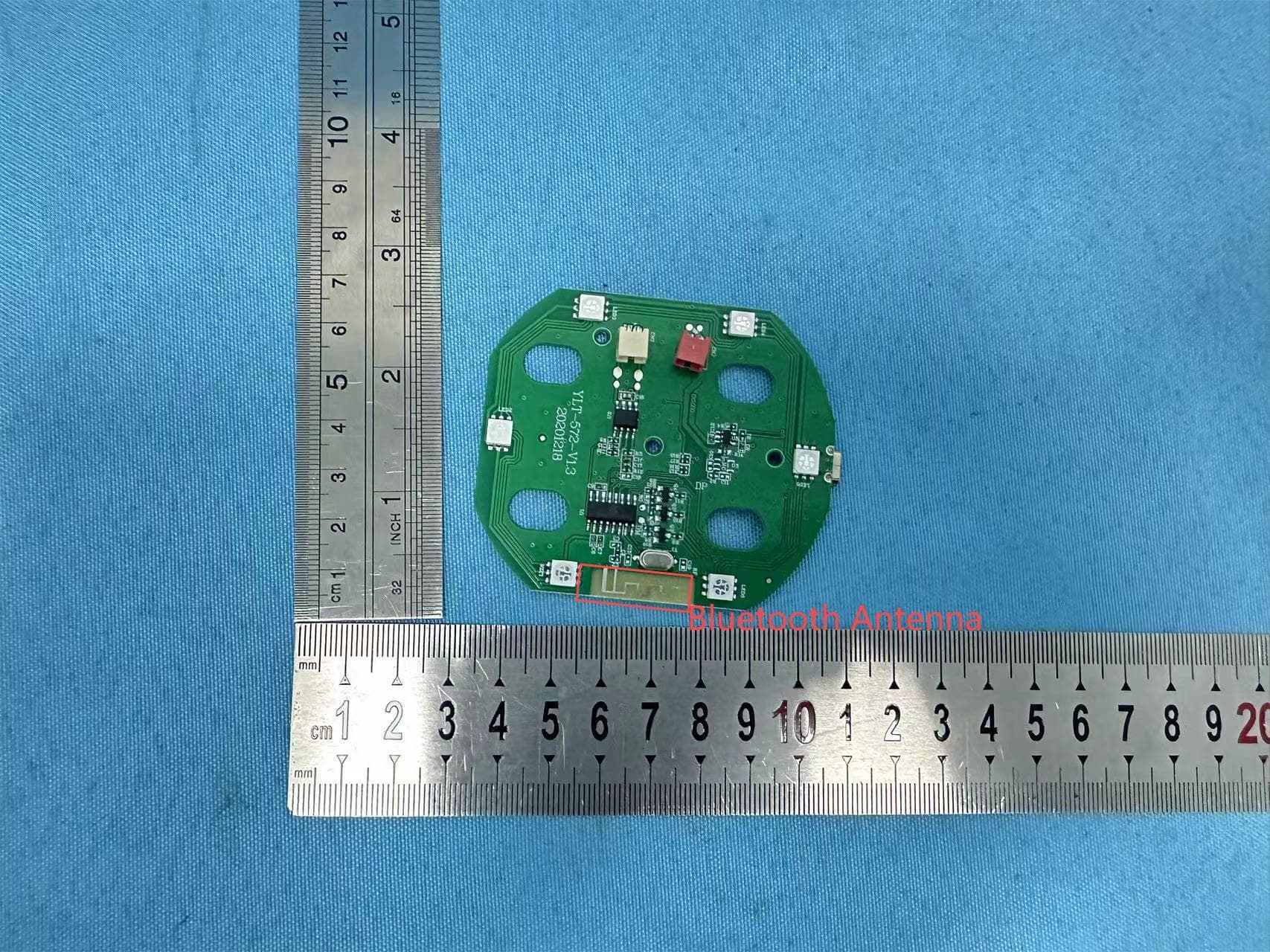
2AANZFLED1
Aug 06, 2024WIRELESS LED SPEAKER
Equipment Class
DSS - Part 15 Spread Spectrum Transmitter