2AANZKRK2Wireless Karaoke Mic
DGL Group LTD.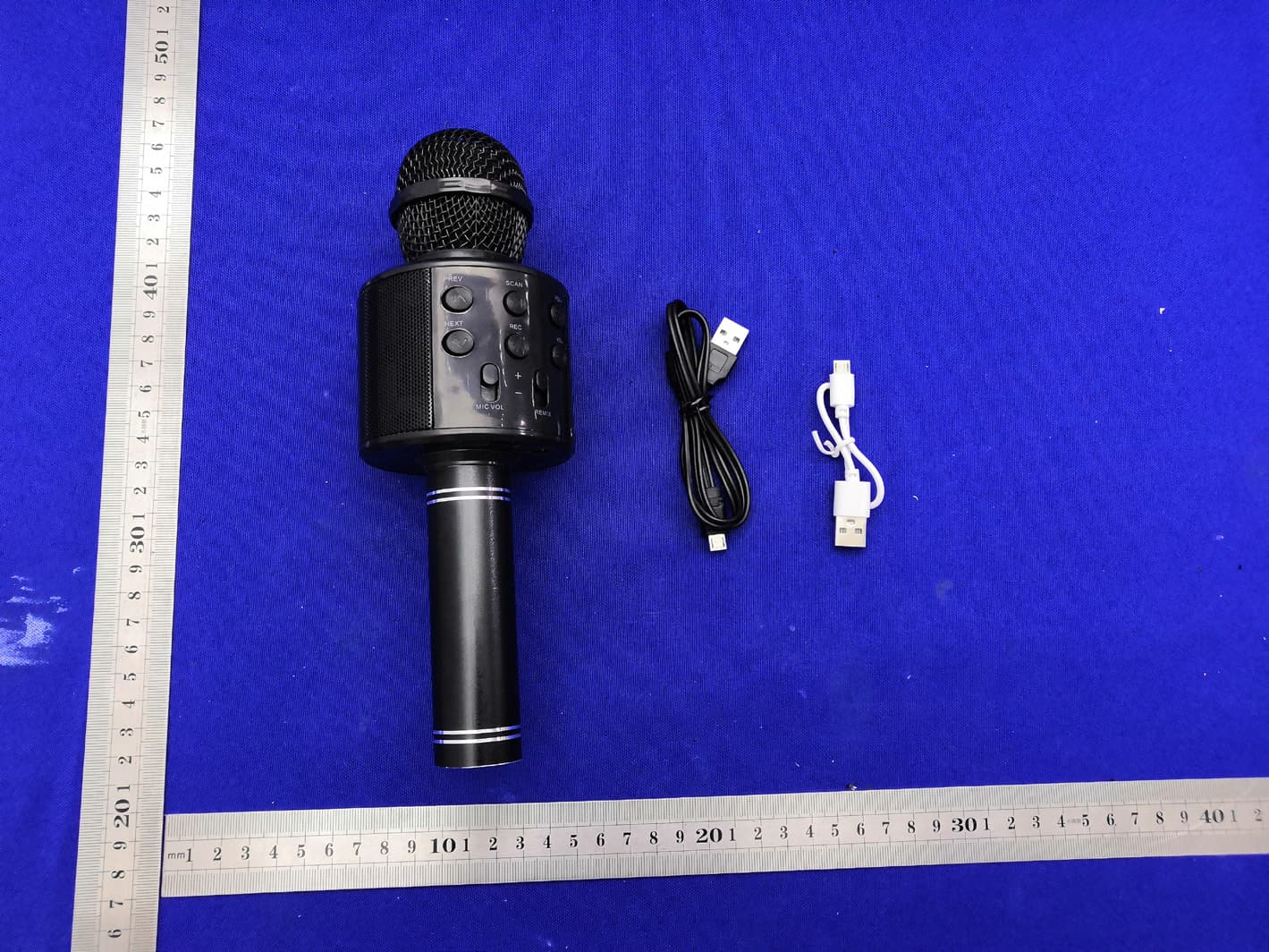
Click to zoom
Application Details
- Equipment Class
- DSS - Part 15 Spread Spectrum Transmitter
- Date of Grant
- Oct 11, 2020
- Application Purpose
- Original Equipment
- Date of Application
- Oct 09, 2020
- Equipment Note
- Wireless Karaoke Mic
- Frequency Range
- 2402.00000000 - 2480.00000000
- Company
- DGL Group LTD.
- Country
- United States
Documents & Files
Document Text
Text extracted from the exhibit documents filed with the FCC. Open a document above to read the original.
Users Manual
Karaoke Wireless Mic + Built-in Speaker Operation Manual HY-PKRK FCC ID: 2AANZKRK2 BT ID: D042258 MADE IN CHINA Thank you for purchasing the Vibe TM Wireless Karaoke Wireless Mic/Speaker & Speaker. Please read all instructions carefully before using and retain this manual for future use and reference. PACKAGE CONTENTS • Karaoke Wireless Mic/Speaker • Micro USB Charging Cable • Operation Manual KEY FEATURES • Compatible with Bluetooth ® -enabled devices • Built-in rechargeable battery • Built-in speaker • Volume and echo control SAFETY INSTRUCTIONS Keep the unit away from heat sources, direct sunlight, humidity, water and any other liquids. Do not operate the unit of it has been exposed to water, moisture or any other liquids to prevent against electric shock, explosion and/or injury to yourself and damage to the unit. Do not use the unit if it has been dropped or damaged in any way. Repairs to electrical equipment should only be performed by the manufacturer. Improper repairs may place the user at serious risk. Do not puncture or harm the exterior surface of the product in any way. Keep the unit free from dust, lint, etc. Do not use this unit for anything other than its intended use or purpose. Doing so may damage the device. This product is not a toy. Keep out of reach of children. Do not expose batteries, battery pack, or batteries to installed to excessive heat, such as direct sunlight, or open flame. DIAGRAM CHARGING THE KARAOKE WIRELESS MIC/SPEAKER The Karaoke Wireless Mic/Speaker comes with a built-in rechargeable battery. Before using it for the first time, we recommend you charge the battery fully. Only use the supplied charge cable to charge the speaker. Connect the USB end to a computer USB port or a USB wall charger and the micro USB to the charge port on the karaoke mic. The red LED indicator will illuminate while the Karaoke Wireless Mic/Speaker is charging. A full charge of the battery takes around 2.5 hours. When the battery is fully charged, the LED indicator will turn off. Disconnect the Karaoke Wireless Mic/Speaker at this point. The Karaoke Wireless Mic/Speaker will then be ready for use. When the battery is low, the LED indicator will flash red and emit three tones every 20 seconds. When this occurs, please recharge the karaoke mic. When using your Karaoke Wireless Mic/Speaker with an iPhone, the top right corner will indicate your karaoke mic’s battery life. PROMPT NOTIFICATION • The Karaoke Wireless Mic/Speaker will notify you during “Power On” with the sound of a beep. • The Karaoke Wireless Mic/Speaker will notify you during "Power off" with a prompt tone. • The Karaoke Wireless Mic/Speaker will notify you when “Pairing Successful” with the sound of a beep. PAIRING THE KARAOKE MIC/SPEAKER 1. Ensure the Karaoke Wireless Mic/Speaker is turned off. If it is not, please turn off the Karaoke Wireless Mic/Speaker first before pairing. 2. Press and hold the multifunction button for 3 seconds until the blue LED indicator flashes. This will indicate your Karaoke Wireless Mic/Speaker is now in pairing mode. 3. Place the Karaoke Wireless Mic/Speaker and the Bluetooth ® device to which you would like to pair it within the operating distance. We recommend keeping the two devices no further than 3 feet apart. 4. Ensure Bluetooth is enabled on your device. Refer to the manufacturer’s instructions for how to enable Bluetooth on your device. 5. Once you have activated Bluetooth on your device, select the Karaoke Wireless Mic/Speaker “VTY-KRK” from the list of available Bluetooth devices. 6. If required, enter the PIN code "0000" and confirm the entry. Note: If pairing is unsuccessful, turn off the Karaoke Wireless Mic/Speaker first and re-pair following the aforementioned steps. Once you have paired the Karaoke Wireless Mic/Speaker with a device, the Karaoke Wireless Mic/Speaker will remember this device and will pair automatically when the device’s Bluetooth is activated and in range. You do not need to re-pair any previously connected devices. OPERATING THE KARAOKE WIRELESS MIC/SPEAKER Playing music wirelessly Once the Karaoke Wireless Mic/Speaker is paired to your device, you can stream music wirelessly to the built-in speaker. Select the track you wish to listen to on your device to play through the speaker. Should you encounter any problems while streaming, please refer to your device’s user manual. Adjust Voice Echo Push the echo switch up or down to adjust voice echo. Adjust Voice Volume Push the volume switch up or down to adjust voice volume. SPECIFICATIONS Bluetooth ® Version: V2.1 + EDR Operating Distance: Up to 33ft (10m) Pick Up: Capacitive Speaker Output: 3W Frequency Range: 150Hz - 18kHz Sensitivity: 80db - 115db Play Time: Up to 3 hours Battery Type: Lithium-Ion Battery Capacity: 1200 mAh Charging Voltage: DC 5V Charging Time: Up to 2.5 Hours Charging Interface: Micro USB Weight: XX lb / XX kg CARE AND MAINTENANCE • Do not expose the unit to excessive heat or humidity to avoid damage to the product's internal circuitry. • Do not use abrasive cleaning solvents to clean the unit. • Do not expose the unit to extremely high or low temperatures as this will shorten the life of the electronic device, destroy the battery, and/or distort certain plastic parts. • Do not dispose of the unit in fire as they may explode or combust. • Do not expose the unit to contact with sharp objects as this will cause scratches and damage. • Do not let the unit fall from high places, as doing so may damage the internal circuitry. • Do not attempt to disassemble the unit. FCC STATEMENT This device complies with part 15 of the FCC Rules. Operation is subject to the following two conditions: (1) This device may not cause harmful interference, and (2) this device must accept any interference received, including interference that may cause undesired operation. FCC INSTRUCTIONS FOR A CLASS B DIGITAL DEVICE OR PERIPHERAL Note: This equipment has been tested and found to comply with the limits for …
Text truncated - open the document above for the full version.
Attestation Statements
DGL Group LTD. Model Difference Product description: Wireless Karaoke Mic Model name: VTY-KRK-ASST, HY-KRK, HY-KRK-RED, HY-KRK-GLD, HY-KRK-BLK, HY-KRK-RSE Trade Name: N/A FCC ID: 2AANZKRK2 All the model are the same circuit and RF module, only for model name. Regards Sincerely Client’s signature: Client’s name / title : Josephine Tran (Manager) Contact information / address: DGL Group, LTD. /195 Raritan Center Parkway Edison, NJ 08837, USA
Cover Letter(s)
C5266091_X8_Ed.1 Letter of Authorization DGL Group LTD. Company: DGL Group LTD. Address: 195 Raritan Center Parkway, Edison, New Jersey, United States Product Name: Wireless Karaoke Mic Model Number: VTY-KRK-ASST, HY-KRK, HY-KRK-RED, HY-KRK-GLD, HY-KRK-BLK, HY-KRK-RSE FCC Identifier: 2AANZKRK2 We authorize LGAI Technological Center S.A., Ronda de la Font delCarme, s/n, 08193 Bellaterra, Spain, to act on our behalf on all matters concerning the above named equipment. Any individual within LGAI Technological Center S.A. is authorized to act on our behalf and take action on the application. We declare that authorize LGAI Technological Center S.A., Ronda de la Font del Carme, s/n, 08193 Bellaterra, Spain, is allowed to forward all information related to the approval project to the Federal Communication Commission and to discuss any issues concerning the approval application. Any and all acts carried out by LGAI Technological Center S.A. on our behalf shall have the same effect as acts of our own. Name: Josephine Tran Date: 2020.09.30 Title: Manager Signature of applicant: 1/1
Cover Letter(s)
C5266091_X10_Ed.2 D ate: 2020.09.30 DGL Group LTD. Office of Engineering Technology Federal Communications Commission 7435 Oakland Mills Road Columbia, MD 21046 Subject: Request for Confidentiality FCC ID: 2AANZKRK2 To Whom It May Concern, Pursuant to the provisions of Sections 0.457 and 0.459 of Commission's rules (47CFR0.457, 0.459), we are requesting the Commission to withhold the following attachment(s) as confidential document from public disclosure. Exhibits Long-Term Confidentiality Short-Term Confidentiality NOTE 2 ID Label/Location No No Attestation Statement No No External Photos No ☐ Block Diagram ☒☐ Schematics ☒☐ Test Report No No Test Setup Photos No ☐ User’s Manual ☐ NOTE 1 ☐ Internal Photos ☐ NOTE 1 ☐ Parts List / Tune Up ☐ ☐ RF Exposure Info No No Operational Description ☒ ☐ Cover Letter(s) No No SDR Software / Security Info ☐ No NO TE 1: Long-Term Confidentiality may be permitted under special conditions (See II. LONG-TERM CONFIDENTIALITY, Section 3 of KDB 726920, use last in force) NOTE 2: Short-Term Confidentiality can be requested for a maximum of 180 days from the date of the grant. A bove mentioned document contains detailed system and equipment description are considered as proprietary information in operation of the equipment. The public disclosure of above documents might be harmful to our company and would give competitor an unfair advantage in the market. I n case of short-term Confidentiality, the applicant requests the exhibits selected above are withheld from public view for a period of ____45__ days from the date of the Grant of Equipment Authorization and prior to marketing. It is our understanding that all measurement test reports, FCC ID label format and correspondent during certification review process cannot be granted as confidential documents and those information will be available for public review once the grant of equipment authorization is issued. 1/1 C5266091_X10_Ed.2 Sincerely, Signature: Name: Josephine Tran Title: Manager 1/1
External Photos
External Photos FCC ID: 2AANZKRK 2
ID Label/Location Info
Model: VTY-KRK-ASST FCC ID: 2AANZKRK2 Label Location
Internal Photos
Internal Photos FCC ID: 2AANZKRK2 ANT AC6925
RF Exposure Info
Shenzhen CTB Testing Co., Ltd. FCC ID:2AANZKRK2 Portable device According to §15.247(e)(i) and §1.1307(b)(1), systems operating under the provisions of this section shall be operated in a manner that ensures that the public is not exposed to radio frequency energy level in excess of the Commission’s guidelines. According to KDB447498 D01 General RF Exposure Guidance V06 The 1-g SAR and 10-g SAR test exclusion thresholds for 100 MHz to 6 GHz at test separation distances ≤ 50 mm are determined by: [(max. power of channel, including tune-up tolerance, mW)/(min. test separation distance, mm)]·[√f(GHZ)] ≤ 3.0 for 1-g SAR and ≤ 7.5 for 10-g extremity SAR, where: • f(GHZ) is the RF channel transmit frequency in GHz • Power and distance are rounded to the nearest mW and mm before calculation • The result is rounded to one decimal place for comparison When the minimum test separation distance is < 5 mm, a distance of 5 mm is applied to determine SAR test exclusion. BT: Modulation Channel Freq. (GHz) Conduct ed power (dBm) Conducte d power (mW) Tune-up power (dBm) Max tune-up power (dBm) Max tune-up power (mW) Distance (mm) Result calculatio n SAR Exclusion threshold SAR test exclusion 2.4024.5942.884±15.003.16<50.980203.00YES 2.4414.5542.854±15.003.16<50.988133.00YES 2.4804.2552.664±15.003.16<50.995993.00YES 2.4025.3683.445±16.003.98<51.234003.00YES 2.4415.2673.365±16.003.98<51.243983.00YES 2.4804.9233.115±16.003.98<51.253883.00YES GFSK Pi/4 DQPSK Conclusion: For the max result : 1.25388W/Kg ≤ FCC Limit 3.0 for 1g SAR.
Test Report
Shenzhen CTB Testing Technology Co., Ltd. Report No.: CTB200914026RFX TEST REPORT Compiled by: Reviewed by: Approved by: Arron Liu Rita Xiao Sherwin Qian/ Director The test report is effective only with both signature and specialized stamp. This result(s) shown in this report refer only to the sample(s) tested. Without written approval of Shenzhen CTB Testing Technology Co., Ltd. this report can’t be reproduced except in full. The tested sample(s) and the sample information are provided by the client. Product Name: Wireless Karaoke Mic FCC ID: 2AANZKRK2 Trademark: N/A Model Number: VTY-KRK-ASST, HY-KRK, HY-KRK-RED, HY-KRK-GLD, HY-KRK-BLK, HY-KRK-RSE Prepared For: DGL Group, LTD. Address: 195 Raritan Center Parkway Edison, NJ 08837, USA Manufacturer: D GL Group, LTD. Address: 195 Raritan Center Parkway Edison, NJ 08837, USA Prepared By: S henzhen CTB Testing Technology Co., Ltd. Address: Floor 1&2, Building A, No. 26 of Xinhe Road, Xinqiao Street, Baoan District, Shenzhen China Sample Received Date: Sep. 8, 2020 Sample tested Date: Sep. 8, 2020 to Sep. 20, 2020 Issue Date: S ep. 20, 2020 Report No.: CTB200914026RFX Test Standards FCC Part15.247 ANSI C63.10:2013 Test Results PASS Remark: This is Bluetooth radio test report. Report Tel: 4008-707-283Web: http://www.ctb-lab.com Page 1 of 54 Shenzhen CTB Testing Technology Co., Ltd. Report No.: CTB200914026RFX TABLE OF CONTENT Test Report Declaration Page 1. VERSION ...................................................................................................... 4 2. TEST SUMMARY ........................................................................................... 5 3. MEASUREMENT UNCERTAINTY .................................................................. 6 4. PRODUCT INFORMATION AND TEST SETUP ............................................... 7 4.1 Product Information ............................................................................................. 7 4.2 Test Setup Configuration ..................................................................................... 7 4.3 Support Equipment .............................................................................................. 7 4.4 Channel List ........................................................................................................ 8 4.5 Test Mode ........................................................................................................... 8 4.6 Test Environment ................................................................................................ 8 5. TEST FACILITY AND TEST INSTRUMENT USED .......................................... 9 5.1 Test Facility ......................................................................................................... 9 5.2 Test Instrument Used .......................................................................................... 9 6. AC POWER LINE CONDUCTED EMISSION ................................................... 11 6.1 Block Diagram Of Test Setup ............................................................................ 11 6.2 Limit ................................................................................................................... 11 6.3 Test procedure .................................................................................................. 11 6.4 Test Result ........................................................................................................ 13 7. RADIATED SPURIOUS EMISSION............................................................... 15 7.1 Block Diagram Of Test Setup ............................................................................ 15 7.2 Limit ................................................................................................................... 15 7.3 Test procedure .................................................................................................. 16 7.4 Test Result ........................................................................................................ 17 8. BAND EDGE AND RF COUNDUCTED SPURIOUS EMISSIONS ................... 26 8.1 Block Diagram Of Test Setup ............................................................................ 26 8.2 Limit ................................................................................................................... 26 8.3 Test procedure .................................................................................................. 26 8.4 Test Result ........................................................................................................ 27 9. COUDUCTED PEAK OUTPUT POWER ........................................................ 32 9.1 Block Diagram Of Test Setup ............................................................................ 32 Report Tel: 4008-707-283 Web: http://www.ctb-lab.com Page 2 of 54 Shenzhen CTB Testing Technology Co., Ltd. Report No.: CTB200914026RFX 9.2 Limit ................................................................................................................... 32 9.3 Test procedure .................................................................................................. 32 9.4 Test Result ........................................................................................................ 33 10. 20DB OCCUPIED BANDWIDTH ................................................................... 36 10.1 Block Diagram Of Test Setup .......................................................................... 36 10.2 Limit ................................................................................................................. 36 10.3 Test procedure ................................................................................................ 36 10.4 Test Result ...................................................................................................... 36 11. CARRIERFREQUENCIES SEPARATION ..................................................... 39 11.1 Bloc…
Text truncated - open the document above for the full version.
Test Setup Photos
Radiated Emission Below 1G A bove 1G FCC ID: 2AANZKRK 2 Conducted Emission
Contact Information
Applicant
Amy Chao
Technical Contact
Non-Technical Contact
Shenzhen CTB Testing Technology Co., Ltd.Simon Lee
[email protected](86) 13662574496
Test Firm
Shenzhen CTB Testing Technology Co., Ltd.Rita Xiao
[email protected]86-13538218145
Technical Specifications
| # | Rule Parts | Frequency Range | Power Output |
|---|---|---|---|
| 1 | 15C | 2.40 GHz - 2.48 GHz | 3.44 mW |
Other Applications from DGL Group LTD.
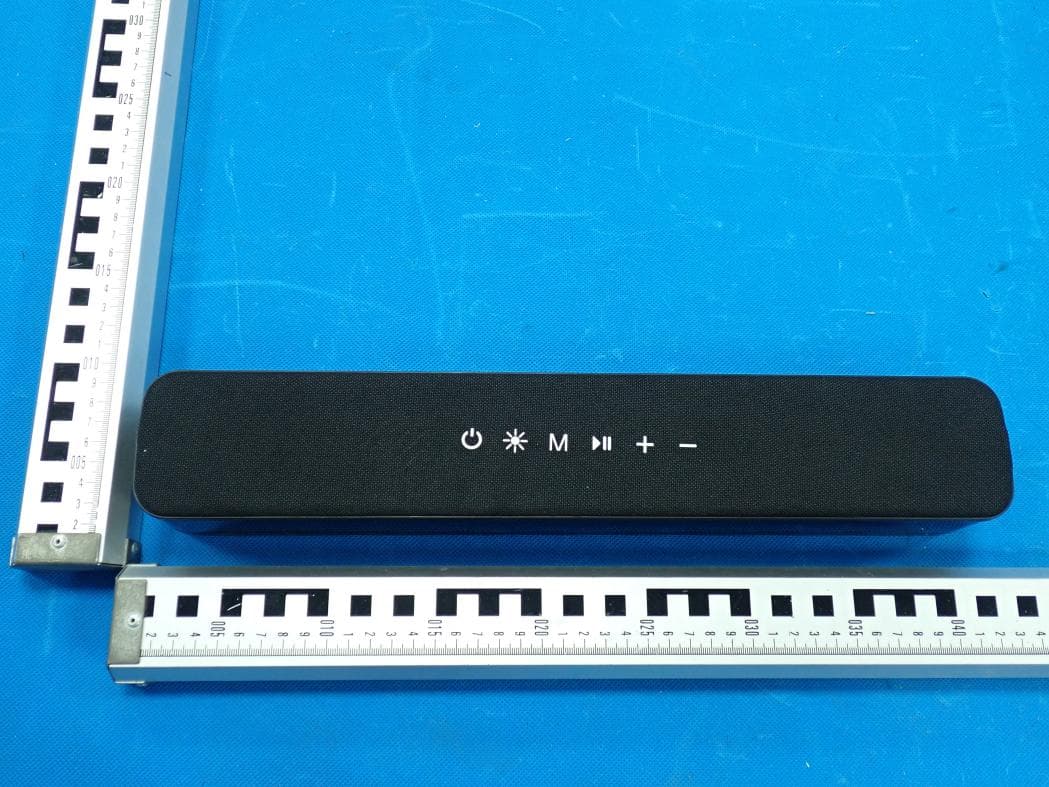
2AANZ-HYLSOBBLK
Jan 28, 2026LED Speaker Bar
Equipment Class
DSS - Part 15 Spread Spectrum Transmitter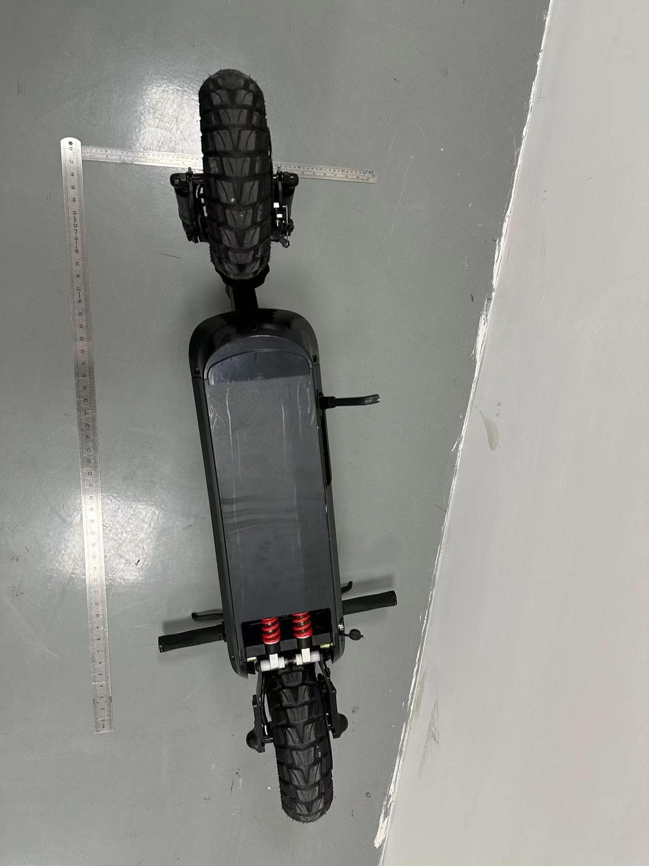
2AANZBSSDM
Oct 14, 2024HOVER-1 PRO SERIES
Equipment Class
DTS - Digital Transmission System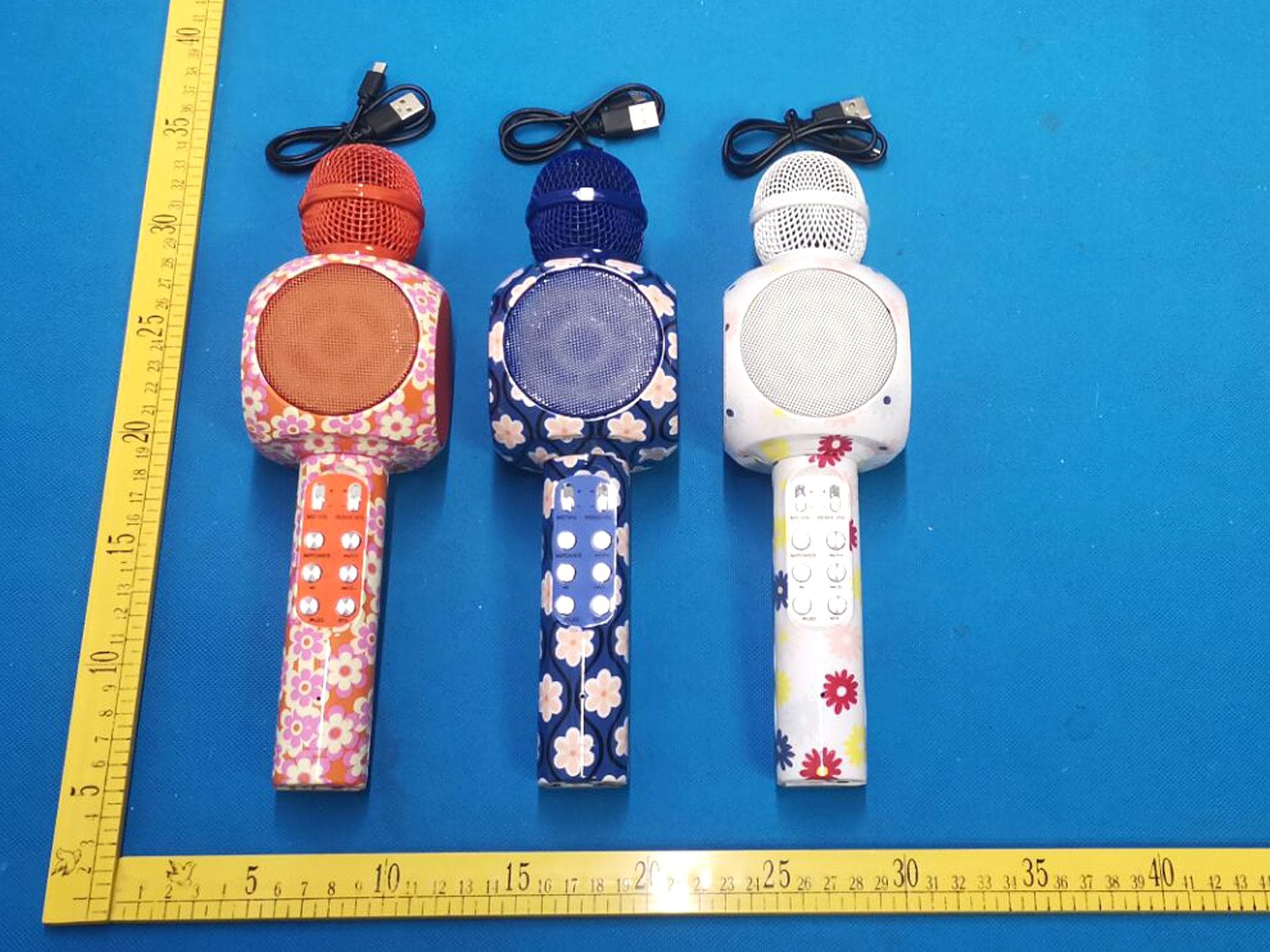
2AANZKRKFLR
Oct 10, 2024Light up Karaoke Mic with Built-in Wireless Speaker
Equipment Class
DTS - Digital Transmission System
2AANZPXLS2
Sep 26, 2024LED Pixie Light Strip
Equipment Class
DTS - Digital Transmission System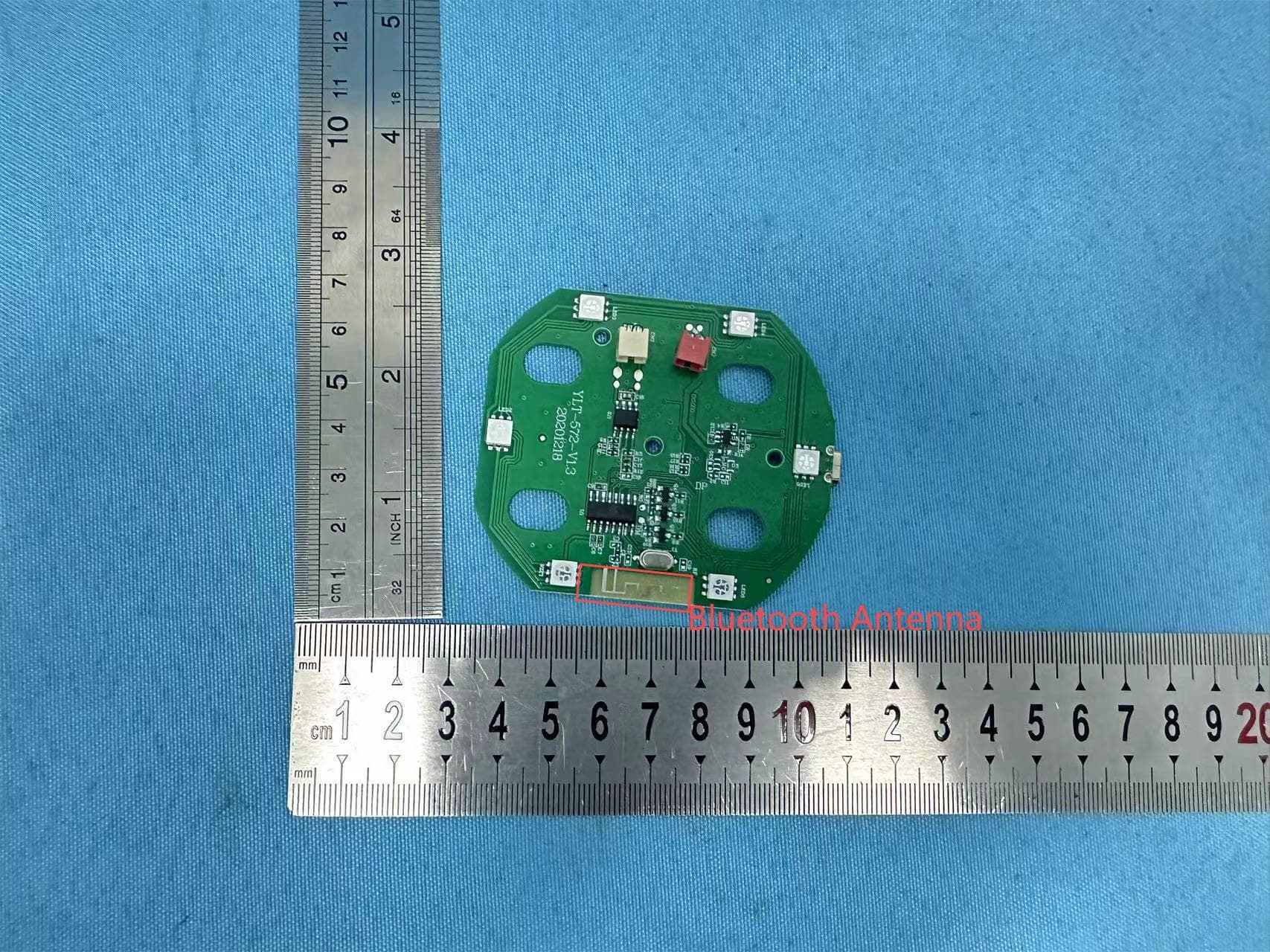
2AANZFLED1
Aug 06, 2024WIRELESS LED SPEAKER
Equipment Class
DSS - Part 15 Spread Spectrum Transmitter