2AANZSTMSRStem Genius RC Speedster/ Roadster
DGL Group LTD.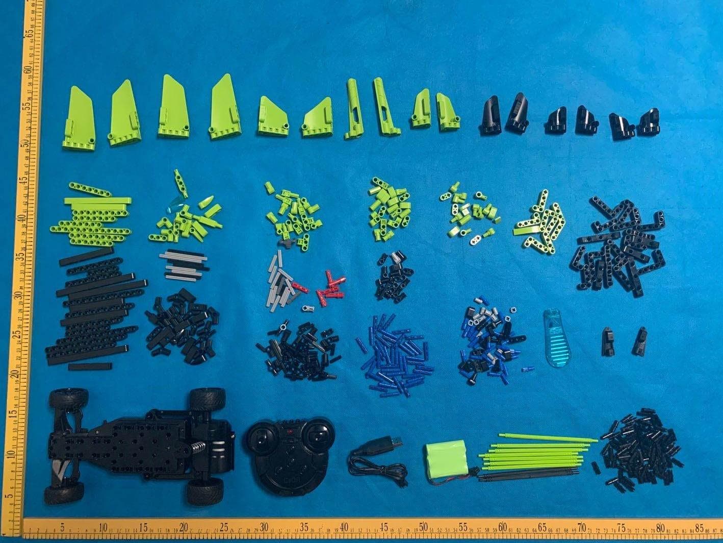
Click to zoom
Application Details
- Equipment Class
- DTS - Digital Transmission System
- Date of Grant
- Jun 07, 2020
- Application Purpose
- Original Equipment
- Date of Application
- Jun 07, 2020
- Equipment Note
- Stem Genius RC Speedster/ Roadster
- Frequency Range
- 2405.00000000 - 2475.00000000
- Company
- DGL Group LTD.
- Country
- United States
Documents & Files
Document Text
Text extracted from the exhibit documents filed with the FCC. Open a document above to read the original.
Users Manual
AGES 6+ REMOTE-CONTROLLED SPEEDSTER INSTRUCTION MANUAL REMOTE-CONTROLLED SPEEDSTER WARNING: CHOKING HAZARD - Small parts. Not for children under 3 years. Adult supervision is required. DGL Toys™ is an innovative division of DGL Group, Ltd. Other trademarks and trade names are those of their respective owners. DGL Toys. 195 Raritan Center Parkway. Edison, NJ 08837. Speci cations, colors and contents may vary from illustrations. Please retain this package for future use. Conforms to safety requirements of ASTM & CPSIA. Operates on 3.6V rechargeable NI-MH battery (include) & 2 AA batteries (not included). BATTERY WARNING: • Do not mix alkaline, standard (carbon zinc), rechargeable (nickel hydride) batteries. • Do not mix old and new batteries. • Non-rechargeable batteries should not be recharged. • Rechargeable batteries should be removed from the appliance before being charged. • Rechargeable batteries should be charged under adult supervision only. • Exhausted batteries should be removed. • The supply terminals should not be short-circuited. • Only batteries of the same or equivalent type are recommended to be used. • Batteries should be inserted with the correct polarity. • Discard button batteries carefully. • Do not allow children to play with button batteries, and keep button batteries out of your child's reach. • Caution hearing aid users to keep hearing aids and batteries out of the reach of children. • Never put button batteries in your mouth for any reason as they are easily swallowed accidentally. • Adults have swallowed button batteries mistaken for pills or tablets. • If a button battery is ingested, immediately seek medical attention. Manufactured in China. Batch Ref: 200514DGL Model Number: STM-SR-ASST FCC ID: 2AANZSTMSR Charging Instructions REMOTE CONTROL 2x1.5V "AA" Batteries Required ( Not included) ONOFF RIGHT TURN LEFT TURN INDICATOR BACKWARD FORWARD AA 1.5V AA 1.5V OPE N RACING Rechargeable NI-MH battery (included) 3.6V 3.6V ON O FF Battery connection Adjust the front wheel alignment Charging time is about 2 hours ●Please use the original USB and rechargeable NI-MH battery for charging. ●Please do not use other products to charge, such as accidents and dangerous think at your own risk! Use 3.6V rechargeable NI-MH battery (included) Power switch Size:210mmX180mm 装订成册,工厂材质 NOTE: This equipment has been tested and found to comply with the limits for a Class B digital device, pursuant to part 15 of the FCC Rules. These limits are designed to provide reasonable protection against harmful interference in a residential installation. This equipment generates uses and can radiate radio frequency energy and, if not installed and used in accordance with the instructions, may cause harmful interference to radio communications. However, there is no guarantee that interference will not occur in a particular installation. If this equipment does cause harmful interference to radio or television reception, which can be determined by turning the equipment o and on, the user is encouraged to try to correct the interference by one or more of the following measures: - Reorient or relocate the receiving antenna. - Increase the separation between the equipment and receiver. -Connect the equipment into an outlet on a circuit di erent from that to which the receiver is connected. -Consult the dealer or an experienced radio/TV technician for help Changes or modi cations not expressly approved by the party responsible for compliance could void the user's authority to operate the equipment. This device complies with Part 15 of the FCC Rules. Operation is subject to the following two conditions: (1) this device may not cause harmful interference, and (2) this device must accept any interference received, including interference that may cause undesired operation.
External Photos
External Photos ALL VIEW OF EUT TOP VIEW OF EUT BOTTOM VIEW OF EUT FRONT VIEW OF EUT BACK VIEW OF EUT LEFT VIEW OF EUT RIGHT VIEW OF EUT
Internal Photos
Internal Photos OPEN VIEW OF EUT-1 OPEN VIEW OF EUT-2 INTERNAL VIEW-1 OF EUT INTERNAL VIEW-2 OF EUT Antenna INTERNAL VIEW-3 OF EUT
Operational Description
DGL Group, Ltd Josephine Tran 195 Raritan Center Parkway Edison, NJ 08837 Declaration concerning Antenna Specification It is hereby declared that the product Model: STM-SR-ASST, STM-SR-GRN, STM-SR-YLW FCC ID: 2AANZSTMSR fulfills the requirement in FCC test relating to the antenna type. The device specified above confirms to the FCC recommendations for internal antenna type(s) described below: Type of antenna: Integral Antenna Gain of the antenna: 0 dBi Frequency range: 2.405 GHz to 2.475GHz The mounting of the antenna is fixed to the radio module and no other antenna should be used. Company name: DGL Group LTD. Address: 195 Raritan Center Parkway Edison, New Jersey United States 08837 Place: New Jersey Date: 2020-06-03 Signature:
RF Exposure Info
RF EXPOSURE EVALUATION 1. PRODUCT INFORMATION Product Description Stem Genius RC Speedster/ Roadster Model Name STM-SR-ASST, STM-SR-GRN, STM-SR-YLW FCC ID 2AANZSTMSR 2. EVALUATION METHOD According to 447498 D01 General RF Exposure Guidance v05 The 1-g and 10-g SAR test exclusion thresholds for 100 MHz to 6 GHz at test separation distances ≤ 50 mm are determined by: [(max. power of channel, including tune-up tolerance, mW)/(min. test separation distance, mm)] ·[√f(GHz)] ≤ 3.0 for 1-g SAR and ≤ 7.5 for 10-g extremity SAR. Where f(GHz) is the RF channel transmit frequency in GHz Power and distance are rounded to the nearest mW and mm before calculation 3. CALCULATION P t =-2.463dBm=0.57mW The value of the Maximum output power P t is referred to the test report of the CFR47 §15.247. The result for RF exposure evaluation SAR=(0.57mW /5mm) .[√2.405(GHz)]= 0.18<3.0 for 1-g SAR and ≤ 7.5 for 10-g extremity SAR. 4. CONCLUSION The SAR evaluation is not required.
Test Report
Page 1 of 42 FCC Test Report Report No.: AGC01559200404FE02 FCC ID : 2AANZSTMSR APPLICATION PURPOSE : Original Equipment PRODUCT DESIGNATION : Stem Genius RC Speedster/ Roadster BRAND NAME : N/A MODEL NAME : STM-SR-ASST, STM-SR-GRN, STM-SR-YLW APPLICANT : DGL GROUP LTD. DATE OF ISSUE : May 27, 2020 STANDARD(S) : FCC Part 15.247 REPORT VERSION : V1.0 Attestation of Global Compliance (Shenzhen) Co., Ltd CAUTION: This report shall not be reproduced except in full without the written permission of the test laboratory and shall not be quoted out of context. Report No.: AGC01559200404FE02 Page 2 of 42 REPORT REVISE RECORD Report Version Revise Time Issued Date Valid Version Notes V1.0 / May 27, 2020 Valid Initial Release Report No.: AGC01559200404FE02 Page 3 of 42 TABLE OF CONTENTS 1. VERIFICATION OF COMPLIANCE ............................................................................................................... 5 2.GENERAL INFORMATION ............................................................................................................................. 6 2.1PRODUCT DESCRIPTION ........................................................................................................................ 6 2.2. TABLE OF CARRIER FREQUENCYS ..................................................................................................... 6 2.3 RELATED SUBMITTAL(S)/GRANT(S) ..................................................................................................... 7 2.4TEST METHODOLOGY ............................................................................................................................ 7 2.5 SPECIAL ACCESSORIES ........................................................................................................................ 7 2.6 EQUIPMENT MODIFICATIONS ............................................................................................................... 7 3. MEASUREMENT UNCERTAINTY ................................................................................................................. 8 4. DESCRIPTION OF TEST MODES ................................................................................................................. 9 5. SYSTEM TEST CONFIGURATION ............................................................................................................. 10 5.1 CONFIGURATION OF TESTED SYSTEM .............................................................................................. 10 5.2 EQUIPMENT USED IN TESTED SYSTEM ............................................................................................. 10 5.3. SUMMARY OF TEST RESULTS ............................................................................................................ 10 6. TEST FACILITY ........................................................................................................................................... 11 7. PEAK OUTPUT POWER ............................................................................................................................. 12 7.1. MEASUREMENT PROCEDURE ........................................................................................................... 12 7.2. TEST SET-UP (BLOCK DIAGRAM OF CONFIGURATION) .................................................................. 12 7.3. LIMITS AND MEASUREMENT RESULT ............................................................................................... 12 8. 6 DB BANDWIDTH ...................................................................................................................................... 15 8.1. MEASUREMENT PROCEDURE ........................................................................................................... 15 8.2. TEST SET-UP (BLOCK DIAGRAM OF CONFIGURATION) .................................................................. 15 8.3. LIMITS AND MEASUREMENT RESULTS ............................................................................................. 15 9. CONDUCTED SPURIOUS EMISSION ........................................................................................................ 17 9.1. MEASUREMENT PROCEDURE ........................................................................................................... 17 9.2. TEST SET-UP (BLOCK DIAGRAM OF CONFIGURATION) .................................................................. 17 9.3. MEASUREMENT EQUIPMENT USED .................................................................................................. 17 9.4. LIMITS AND MEASUREMENT RESULT ............................................................................................... 17 10. MAXIMUM CONDUCTED OUTPUT POWER SPECTRAL DENSITY ....................................................... 22 Report No.: AGC01559200404FE02 Page 4 of 42 10.1 MEASUREMENT PROCEDURE .......................................................................................................... 22 10.2 TEST SET-UP (BLOCK DIAGRAM OF CONFIGURATION) ................................................................. 22 10.3 MEASUREMENT EQUIPMENT USED ................................................................................................. 22 10.4 LIMITS AND MEASUREMENT RESULT .............................................................................................. 22 11. RADIATED EMISSION ............................................................................................................................... 24 11.1. MEASUREMENT PROCEDURE ......................................................................................................... 24 11.2. TEST SETUP ....................................................................................................................................... 25 11.3. LIMITS AND MEASUREMENT RESULT ............................................................................................. 26 11.4. TEST RESULT .....................................…
Text truncated - open the document above for the full version.
Test Setup Photos
Test Setup Photos RADIATED EMISSION TEST SETUP BELOW 1GHZ RADIATED EMISSION TEST SETUP ABOVE 1GHZ
Contact Information
Applicant
Amy Chao
Test Firm
Attestation of Global Compliance (Shenzhen) Co., LDoris Li
[email protected]+86-755-25234088
Technical Specifications
| # | Rule Parts | Frequency Range | Power Output |
|---|---|---|---|
| 1 | 15C | 2.40 GHz - 2.48 GHz | 600.00 µW |
Other Applications from DGL Group LTD.
2AANZ-HYLSOBBLK
Jan 28, 2026LED Speaker Bar
Equipment Class
DSS - Part 15 Spread Spectrum Transmitter
2AANZBSSDM
Oct 14, 2024HOVER-1 PRO SERIES
Equipment Class
DTS - Digital Transmission System
2AANZKRKFLR
Oct 10, 2024Light up Karaoke Mic with Built-in Wireless Speaker
Equipment Class
DTS - Digital Transmission System
2AANZPXLS2
Sep 26, 2024LED Pixie Light Strip
Equipment Class
DTS - Digital Transmission System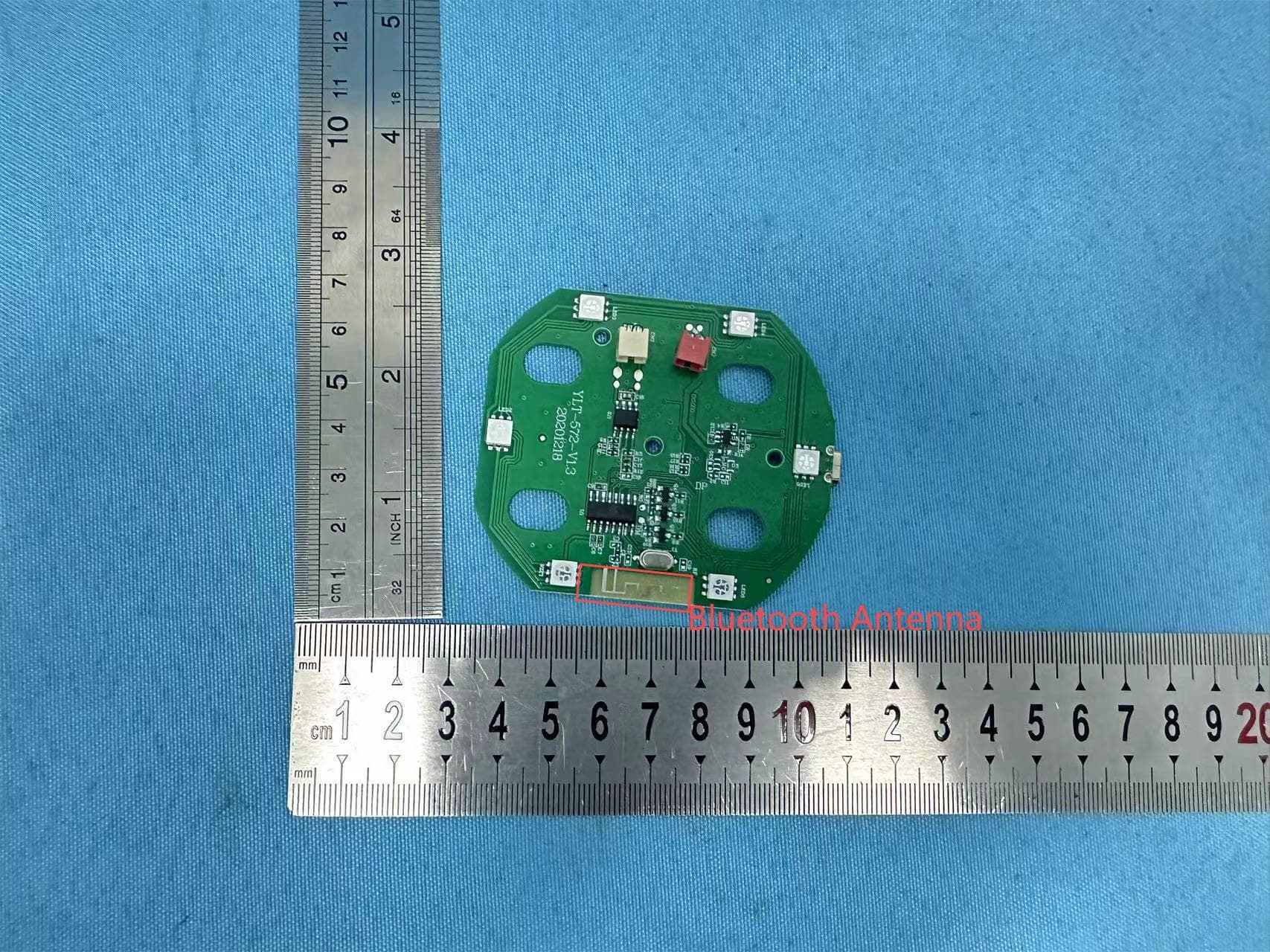
2AANZFLED1
Aug 06, 2024WIRELESS LED SPEAKER
Equipment Class
DSS - Part 15 Spread Spectrum Transmitter