2AANZTW20TRUE WIRELESS EARBUDS & POWER BANK
DGL Group LTD.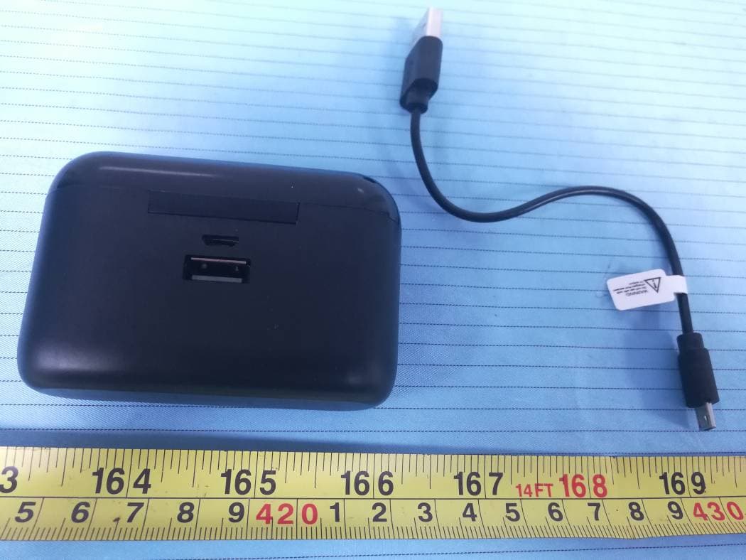
Click to zoom
Application Details
- Equipment Class
- DSS - Part 15 Spread Spectrum Transmitter
- Date of Grant
- Nov 23, 2020
- Application Purpose
- Original Equipment
- Date of Application
- Nov 23, 2020
- Equipment Note
- TRUE WIRELESS EARBUDS & POWER BANK
- Frequency Range
- 2402.00000000 - 2480.00000000
- Company
- DGL Group LTD.
- Country
- United States
Documents & Files
Document Text
Text extracted from the exhibit documents filed with the FCC. Open a document above to read the original.
Users Manual
TRUE WIRELESS EARBUDS & POWER BANK QUICK START GUIDE X8 2 3 Turn on Bluetooth on your phone or tablet. Choose “X8”. Enter “0000” if asked. You’re paired! To turn OFF press and hold the multifunction button on either earbud. The charging case can be used to charge your USB compatible devices. When the case is charged. Plug your charging cable into your device. And connect the USB tip into the back of the USB port of the earbud case. USING THE CASE TO CHARGE YOUR DEVICES Your device will immediately begin to charge. Use only the cables supplied for this product. CONNECTION LOST? • If only one earbud works, turn off the earbud and reconnect earbuds as a pair. If paired two earbuds don’t work, turn off the earbud and reconnect earbuds as a pair. • Make sure your earbuds are within range of your smart device. • If you hear a long beep, you need to recharge your earbuds. Connection may be lost due to low battery. NOTE: When answering calls, the call can be heard and controlled by the main earbud only. USING THE PORTABLE CHARGING CASE SPECIFICATIONS We recommend that you keep the earbuds in the portable charge case when not in use. While on-the-go, the case doubles as a charging solution for the earbuds and also a power bank to charge your devices. To charge: simply put the earbuds into the charging case. Make sure the earbuds fit securely inside the case. Charge the earbuds before using the first time. Connect the Micro USB cable to the charging port on case. A full charge of the case battery takes up to 4 hour. When the case is charging, the LED light will be red then turn blue when fully charged. Remove the cable your earbuds and case are ready to go. Your earbuds come pre-paired. Just put both earbuds back into charging box, and then take out, it will power on and pairing. If they lose connection, please follow the below steps to reconnect. Press and hold multifunction buttons on both earbuds to power on both earbuds, then wait till the indicator lights flash red and blue on the main earbud. The two earbuds will pair to each other automatically. The indicator lights of both earbuds will flash blue three times to indicate they are paired successfully. turning the equipment off and on, the user is encouraged to try to correct the interference by one or more of the following measures: • Reorient or relocate the receiving antenna. • Increase the separation between the equipment and receiver. • Connect the equipment into an outlet on a circuit different from that to which the receiver is connected. • Consult the dealer or an experienced radio/TV technician for help. This equipment complies with FCC radiation exposure limits set forth for an uncontrolled environment . FCC STATEMENT This device complies with part 15 of the FCC Rules. Operation is subject to the following two conditions: (1) This device may not cause harmful interference, and (2) this device must accept any interference received, including interference that may cause undesired operation. Please note that changes or modifications not expressly approved by the party responsible for compliance could void the user’s authority to operate the equipment. FCC INSTRUCTIONS FOR A CLASS B DIGITAL DEVICE OR PERIPHERAL Note: This equipment has been tested and found to comply with the limits for a Class B digital device, pursuant to part 15 of the FCC Rules. These limits are designed to provide reasonable protection against harmful interference in a residential installation. This equipment generates, uses and can radiate radio frequency energy and, if not installed and used in accordance with the instructions, may cause harmful interference to radio communications. However, there is no guarantee that interference will not occur in a particular installation. If this equipment does cause harmful interference to radio or television reception, which can be determined by WARRANTY This product is covered by a 3 month limited manufacturer’s warranty. Contact us if you have any problems at [email protected]. WARNING Keep away from water and moisture. Keep away from heat sources. Do not disassemble. 1 TRUE WIRELESS EARBUDS & POWER BANK QUICK START GUIDE TRUE WIRELESS EARBUDS & POWER BANK QUICK START GUIDE TRUE WIRELESS EARBUDS & POWER BANK QUICK START GUIDE TRUE WIRELESS EARBUDS & POWER BANK QUICK START GUIDE MULTI-FUNCTION CONTROLS Increase volume: Press and hold the main earbud button for 2 seconds Decrease volume: Press and hold the secondary earbud button for 2 seconds Next Track: Press the main earbud button twice Previous Track: Press the secondary earbud twice Receive Call / End Call: Press the main earbud button once Activate your smart device’s voice assistant: Press the main earbud button three times. When your earbuds are on, one of them will automatically be assigned as a main earbud and the other as a secondary earbud. Each earbud button has different controls: TRUE WIRELESS EARBUDS & POWER BANK QUICK START GUIDE TRUE WIRELESS EARBUDS & POWER BANK QUICK START GUIDE TRUE WIRELESS EARBUDS & POWER BANK QUICK START GUIDE TRUE WIRELESS EARBUDS & POWER BANK QUICK START GUIDE TRUE WIRELESS EARBUDS & POWER BANK QUICK START GUIDE TRUE WIRELESS EARBUDS & POWER BANK QUICK START GUIDE Model: FB-TW20 Play Time: Up to 12hrs Battery capacity: 40mAh Earbud Charging Time: 1.5 hrs Case/Power Bank Charging Time: 3-4 hrs Operation Range: Up to 30ft. (10m) Operating temperature range: -10 o C~55 o C FCC ID: 2AANZTW20 BT ID: D044460
Block Diagram
33 . 7 V BAT
Cover Letter(s)
DGL Group LTD. 195 Raritan Center Parkway Edison New Jersey,08837,United States Te l : 001-732-692-5149 Fax: 001-732-692-5000 E-Mail: [email protected] Date:11/04/2020 To : FEDERAL COMMUNICATIONS COMMISSION Authorization and Evaluation Division 7435 Oakland Mills Road Columbia, MD 21046 We, DGL Group LTD., hereby declare that The RF chip, model: AB5376A2, installed in our product named as TRUE WIRELESS EARBUDS & POWER BANK ;Model No: FB-TW20 FCC ID:2AANZTW20 ,which support Bluetooth BDR(GFSK) , EDR(π/4‐DQPSK), EDR(8DPSK), BLE, for use in the US marketing this chip will not support/enable the BLE. And BLE function has been shielded by the manufacturer by using the software. Sincerely Yo u rs, Signature: Printed Name: Josephine Tran Title: Production Design / Project Manager
Cover Letter(s)
DGL Group LTD. 195 Raritan Center Parkway Edison New Jersey,08837,United States Tel: 001-732-692-5149 Fax: 001-732-692-5000 E-Mail: [email protected] Date:11/04/2020 We, DGL Group LTD., hereby declare that Our product, TRUE WIRELESS EARBUDS & POWER BANK, Model number: FB-TW20, FCC ID: 2AANZTW20 is a twins earphone that has a left earphone and a right earphone. We would like to declare that the left earphone and the right earphone are identical in the Antenna & RF circuits. So only choose the one of two earphones to test. We confirm that all information above is true, and we’ll be responsible for all the consequences. Please contact me if you have any question. Sincerely Yours, Signature: Printed Name: Josephine Tran Title: Production Design / Project Manager
Cover Letter(s)
DGL Group LTD. 195 Raritan Center Parkway Edison New Jersey,08837,United States Tel: 001-732-692-5149 Fax: 001-732-692-5000 E-Mail: [email protected] FCC Authorization 11/03/2020 FEDERAL COMMUNICATIONS COMMISSIONS Authorization and Evaluation Division 7435 Oakland Mills Road Columbia, MD 21046 Subject: Agent Authorization To whom it may concern: We, DGL Group LTD., the undersigned, hereby authorize Bay Area Compliance Laboratories Corporation to act on its behalf in all matters relating to application for Equipment authorization, including the signing of all documents relating to these matters. All acts carried out by Bay Area Compliance Laboratory Corporation on our behalf shall have the same effect as our own action. We, the undersigned, hereby certify that we are not subject to a denial of federal benefits, that includes FCC benefits, pursuant to Section 5301 of the Anti-Drug Abuse Act of 1988, 21 U.S.C. 862. This authorization is valid until further written notice from the applicant. Sincerely Yours, Signature: Printed Name: Josephine Tran Title: Production Design / Project Manager
Cover Letter(s)
DGL Group LTD. 195 Raritan Center Parkway Edison New Jersey,08837,United States Tel: 001-732-692-5149 Fax: 001-732-692-5000 E-Mail: [email protected] Date:11/04/2020 FCC ID Cover Letter The DGL Group LTD. here by submits justification for placing the FCC ID in the Associated User Manual. According to the FCC Regulation and Guidance (KDB Publication 784748 D01 v09r01) allows for the FCC ID to be moved to the User’s manual if the device is unquestionably too small for the FCC ID to be printed. Referring to the above quote, as the device is too small (FCC ID: 2AANZTW20 ) to be printed. The FCC ID will be moved to the last page of user’s manual and charging case. The details are as below: A. Side surface (A): The curvature shape of the silicone sleeve back cover is not flat, so it’s hard to affix thelabel on the surface of the earbuds. B. Top cover (B): The plastic logo of the top cover does not provide enough physical space to fit the printing of the FCC ID according to below reference picture. Conclusion: Based on the above description of area A to B, we conclude that the device is unquestionably too samll for enabling the FCC ID to be printed onto any surface, We therefore request to move the FCC ID to the User manual and charging case Sincerely Yours, Signature: Printed Name: Josephine Tran Title: Production Design / Project Manager
External Photos
Bay Area Compliance Laboratories Corp. (Shenzhen) Project No.: RSZ201012839-RF Page 1 of 7 EXHIBIT B - EUT EXTERNAL PHOTOGRAPHS Left ear Bay Area Compliance Laboratories Corp. (Shenzhen) Project No.: RSZ201012839-RF Page 2 of 7 Bay Area Compliance Laboratories Corp. (Shenzhen) Project No.: RSZ201012839-RF Page 3 of 7 Bay Area Compliance Laboratories Corp. (Shenzhen) Project No.: RSZ201012839-RF Page 4 of 7 Right ear Bay Area Compliance Laboratories Corp. (Shenzhen) Project No.: RSZ201012839-RF Page 5 of 7 Bay Area Compliance Laboratories Corp. (Shenzhen) Project No.: RSZ201012839-RF Page 6 of 7 Bay Area Compliance Laboratories Corp. (Shenzhen) Project No.: RSZ201012839-RF Page 7 of 7
ID Label/Location Info
Bay Area Compliance Laboratories Corp. (Shenzhen) Project No.: RSZ201012839-RF EXHIBIT A - FCC ID LABEL AND LOCATION FCC ID Label FCC ID Label Location Information The label shown shall be permanently affixed at a conspicuous location on the device and be readily visible to the user at the time purchase (Labeling requirements per 2.925)
Internal Photos
Bay Area Compliance Laboratories Corp. (Shenzhen) Project No.: RSZ201012839-RF Page 1 of 4 EXHIBIT C - EUT INTERNAL PHOTOGRAPHS Left ear BT Antenna Bay Area Compliance Laboratories Corp. (Shenzhen) Project No.: RSZ201012839-RF Page 2 of 4 Bay Area Compliance Laboratories Corp. (Shenzhen) Project No.: RSZ201012839-RF Page 3 of 4 Right ear BT Antenna Bay Area Compliance Laboratories Corp. (Shenzhen) Project No.: RSZ201012839-RF Page 4 of 4
Operational Description
Circuit Description 1 When the headset is in shutdown state, press the button, and the IC8 pin determines to boot through the internal MCU. The battery is formed by IC step-down module and IC5 pin 10UH inductance to form a step-down circuit, which supplies power to the IC internal RF module and the power amplifier circuit of the headset. The battery has two LDO step-down circuits, IC3 for IO port power supply and IC19 for DAC circuit power supply. 11, 12 pin and IC internal circuit and 26MHZ crystal oscillator constitute the oscillation circuit, to provide reference signal to IC internal. IC13 and 14 legs are used to drive red light and blue light, indicating that bluetooth works in pairing state; 2. At this time, the mobile phone searches and connects the headset, and plays music. The Bluetooth antenna receives the R3 and C6 impedance matching network elements that pass through 2.4g RF digital signals, and enters the Bluetooth IC9 pin. Through the internal RADIO frequency module, touch code circuit, digital-to-analog conversion circuit and power amplifier circuit, to bluetooth IC17 and 18 pin output audio signal, push the horn to work. 3 when there is a telephone, press the button to answer it. The voice audio signal received by MIC is input to IC16 pin through 104 capacitor, amplified and coded internally, and then sent to the mobile phone by antenna through internal RF module circuit and R3 and C6 impedance matching network components; The voice of the other party's mobile phone is sent to the Bluetooth headset through the Bluetooth of our mobile phone. After the IC internal circuit processing, to the Bluetooth IC17 and 18 pin output audio signal, at this time can hear the other side's voice. 4. The charging case circuit is boosted to 5V to the spring pin, and the headset copper column is input to the Bluetooth IC2 pin through THE VUSB network, and the battery is charged through the bluetooth IC4 pin through the internal charging circuit. At this time, the headset is in charging state, the red light is always on, after charging the ear will automatically shut down.
Schematics
D C B A 1 2 3 4 5 6 A B C D 6 5 4 3 2 1 USB³äμç μç³Ø MIC ° ́¼ü Ö ̧ʾμÆ C14 6.8K R5 104 2 1 MIC L1 10uH C8 105 C3 106 C2 225 C7 225 L3 1P L4 NC R3 2.7NH C13 104 C12 104 Y1 26MHZ K1 3X3X0.8 R-LED RED B-LED BLUE BT1 4.2V C1 105 UPDATE 1 GND 2 5V B- B+ 10 VDDBT 7 VDDBT 8 PWRKEY 5 LX 6 DGND 4 VBAT 2 VUSB 18 DACL 16 ADC10/MIC/PF2 11 BT_OSCI 12 BT_OSCO 9 BT_ANT 3 VDDIO 19 VDDDAC 1 AGND 0 RFGND 17 VCMBUF 20 VDDPA 13 ADC6/PB4 14 ADC5/PB3 15 ADC2/PA7 U2 AB5376A2 QFN20 3*3 AB5376A2 QFN20 3*3 ANT1 3216 L+ L- C10 102 C9 102 C33 L3 L2 1K/1G VDDIO PWRKEY BT_ANT MICIN VDDBT VDDDAC VUSB VBAT VDDDAC VUSB CHRG_LED BLUE_LED/UPDATE VBAT OSCO BT_RF PWRKEY VDDBT OSCI BLUE_LED/UPDATE CHRG_LED DACL# DACL MICIN DACL DACL#
Test Report
Note: This report may contain data that are not covered by the A2LA accreditation and are marked with an asterisk “★”. BACL is not responsible for the authenticity of any test data provided by the applicant. Data included from the applicant that may affect test results are marked with an asterisk ’*’. Customer model name, addresses, names, trademarks etc. are not considered data. This report cannot be reproduced except in full, without prior written approval of the Company. Unless otherwise stated the results shown in this test report refer only to the sample(s) tested. This report is valid only with a valid digital signature. The digital signature may be available only under the Adobe software above version 7.0. FCC PART 15.247 TEST REPORT For DGL Group LTD. 195 Raritan Center Parkway, Edison, New Jersey, United States, 08837 FCC ID: 2AANZTW20 Report Type: Original Report Product Type: TRUE WIRELESS EARBUDS & POWER BANK Re port Number: RSZ201012839-00 Re port Date: 2020-11-17 Reviewed B y: Nancy Wang RF En gineer Prepared By: Bay Area Compliance Laboratories Corp. (Shenzhen) 6/F., West Wing, Third Phase of Wanli Industrial Building, Shihua Road, Futian Free Trade Zone, Shenzhen, Guangdong, China Tel: +86-755-33320018 Fax: +86-755-33320008 www.baclcorp.com.cn Bay Area Compliance Laboratories Corp. (Shenzhen) Report No.: RSZ201012839-00 FCC Part 15.247 Page 2 of 57 TABLE OF CONTENTS GENERAL INFORMATION ....................................................................................................................................... 4 PRODUCT DESCRIPTION FOR EQUIPMENT UNDER TEST (EUT) ..................................................................................... 4 OBJECTIVE ................................................................................................................................................................... 4 TEST METHODOLOGY .................................................................................................................................................. 4 MEASUREMENT UNCERTAINTY .................................................................................................................................... 5 TEST FACILITY ............................................................................................................................................................. 5 SYSTEM TEST CONFIGURATION .......................................................................................................................... 6 DESCRIPTION OF TEST CONFIGURATION ...................................................................................................................... 6 EUT EXERCISE SOFTWARE .......................................................................................................................................... 6 SPECIAL ACCESSORIES ................................................................................................................................................. 6 EQUIPMENT MODIFICATIONS ....................................................................................................................................... 6 SUPPORT EQUIPMENT LIST AND DETAILS .................................................................................................................... 6 EXTERNAL I/O CABLE .................................................................................................................................................. 6 BLOCK DIAGRAM OF TEST SETUP ................................................................................................................................ 7 SUMMARY OF TEST RESULTS ............................................................................................................................... 8 TEST EQUIPMENT LIST ........................................................................................................................................... 9 FCC§15.247 (i), §1.1307 (b) (1) &§2.1093 – RF EXPOSURE ...................................................................................... 11 APPLICABLE STANDARD ............................................................................................................................................ 11 FCC §15.203 – ANTENNA REQUIREMENT .......................................................................................................... 12 APPLICABLE STANDARD ............................................................................................................................................ 12 ANTENNA CONNECTOR CONSTRUCTION .................................................................................................................... 12 FCC §15.207 (a) – AC LINE CONDUCTED EMISSIONS ..................................................................................... 13 APPLICABLE STANDARD ............................................................................................................................................ 13 EUT SETUP ................................................................................................................................................................ 13 EMI TEST RECEIVER SETUP ....................................................................................................................................... 13 TEST PROCEDURE ...................................................................................................................................................... 13 CORRECTED FACTOR & MARGIN CALCULATION ....................................................................................................... 14 TEST DATA ................................................................................................................................................................ 14 FCC §15.205, §15.209 & §15.247(d) – RADIATED EMISSIONS ........................................................................... 17 A…
Text truncated - open the document above for the full version.
Test Setup Photos
Bay Area Compliance Laboratories Corp. (Shenzhen) Project No.: RSZ201012839-RF EXHIBIT D - TEST SETUP PHOTOGRAPHS Conducted Emissions - Front View Conducted Emissions - Side View Bay Area Compliance Laboratories Corp. (Shenzhen) Project No.: RSZ201012839-RF Radiated Emissions View (Below 1 GHz) Radiated Emissions View (Above 1 GHz)
Contact Information
Applicant
Amy Chao
Test Firm
Bay Area Compliance Laboratories Corp. (Shenzhen)Well Wang
[email protected]+86 (0) 755 33320018
Technical Specifications
| # | Rule Parts | Frequency Range | Power Output |
|---|---|---|---|
| 1 | 15C | 2.40 GHz - 2.48 GHz | 1.00 mW |
Other Applications from DGL Group LTD.
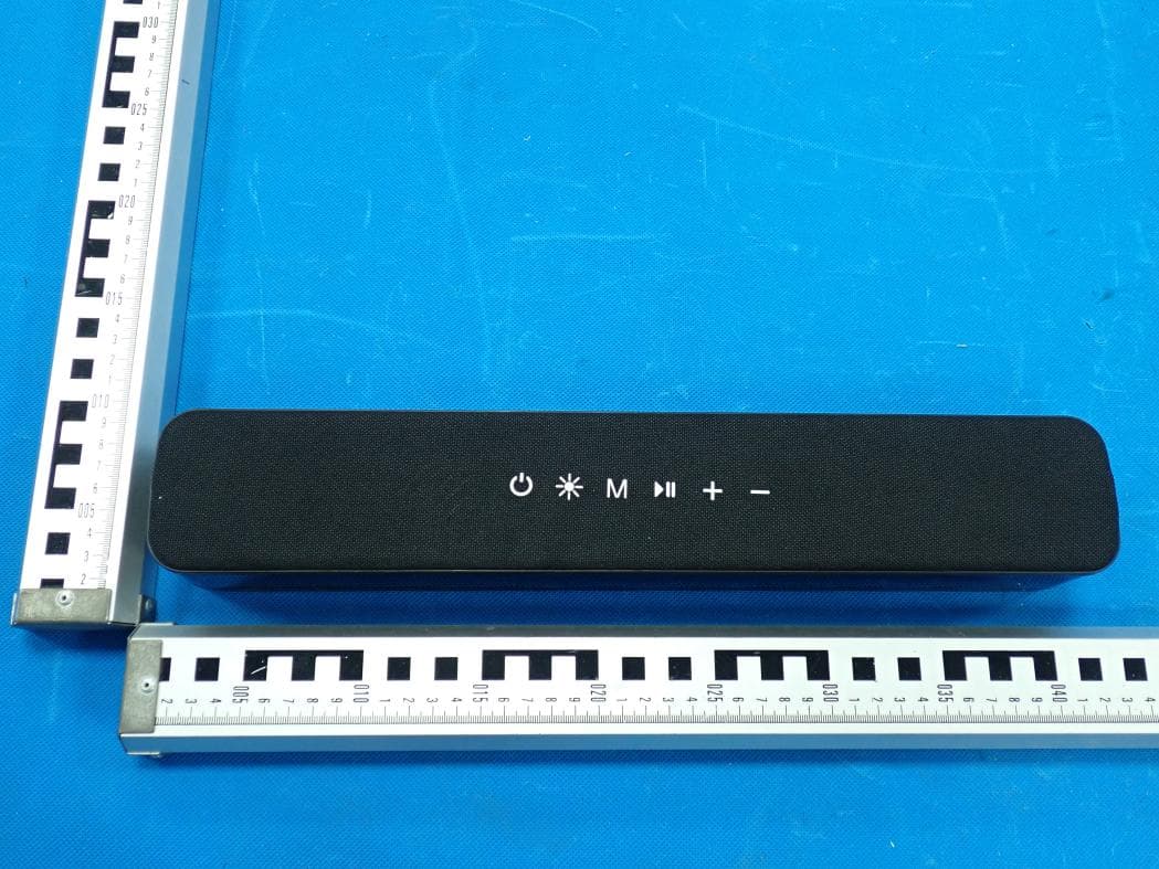
2AANZ-HYLSOBBLK
Jan 28, 2026LED Speaker Bar
Equipment Class
DSS - Part 15 Spread Spectrum Transmitter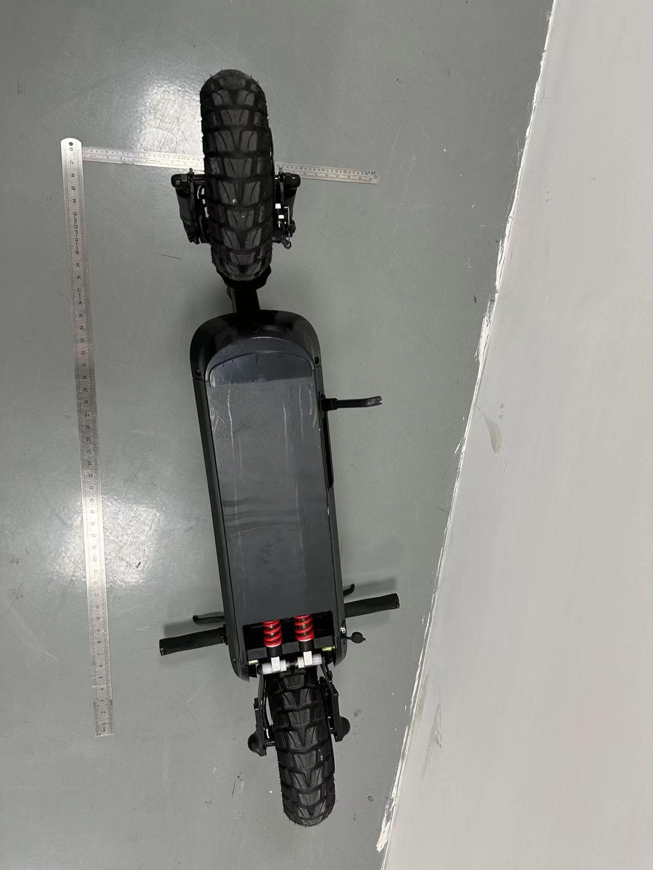
2AANZBSSDM
Oct 14, 2024HOVER-1 PRO SERIES
Equipment Class
DTS - Digital Transmission System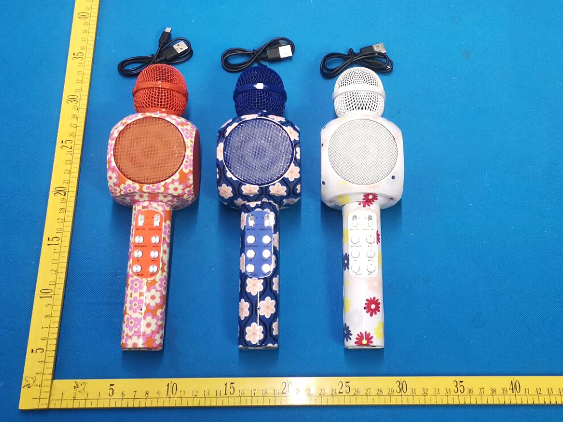
2AANZKRKFLR
Oct 10, 2024Light up Karaoke Mic with Built-in Wireless Speaker
Equipment Class
DTS - Digital Transmission System
2AANZPXLS2
Sep 26, 2024LED Pixie Light Strip
Equipment Class
DTS - Digital Transmission System
2AANZFLED1
Aug 06, 2024WIRELESS LED SPEAKER
Equipment Class
DSS - Part 15 Spread Spectrum Transmitter