2AAP7SAU1AT1Optima 900MHz USA
Salus Limited.
Click to zoom
Application Details
- Equipment Class
- DXX - Part 15 Low Power Communication Device Transmitter
- Date of Grant
- Apr 29, 2014
- Application Purpose
- Original Equipment
- Date of Application
- Apr 29, 2014
- Equipment Note
- Optima 900MHz USA
- Frequency Range
- 908.50000000 - 919.74000000
- Company
- Salus Limited.
- Country
- China
Documents & Files
Document Text
Text extracted from the exhibit documents filed with the FCC. Open a document above to read the original.
Users Manual
Model: 105.20001410 Kenmore™ Smart Thermostat P/N XXXXXXXXX Se ars Brands Management Corporation, Hoffman Estates, IL 60179 www.k enmore.com www.se ars.com www.kmart.com Use & Car e Guide KENMORE LIMITED WARRANTY FOR ONE YEAR from the date of sale this product is warranted against defects in material or workmanship when it is correctly connected, operated and maintained according to all supplied instructions. WITH PROOF OF SALE, return a defective product to the retailer from which it was purchased for free replacement. This warranty is void if this product is ever used for other than private household purposes. This warranty covers ONLY defects in material and workmanship, and will NOT pay for: 1. 2. 3. Disclaimer of implied warranties; limitation of remedies Customer’s sole and exclusive remedy under this limited warranty is product replacement as provided herein. Implied warranties, including warranties of merchantability or fitness for a particular purpose, are limited to one year or the shortest period allowed by law. Seller shall not be liable for incidental or consequential damages. Some states and provinces do not allow the exclusion or limitation of incidental or consequential damages, or limitation on the duration of implied warranties of merchantability or fitness, so these exclusions or limitations may not apply to you. This warranty gives you specific legal rights, and you may also have other rights which vary from state to state. Sears Brands Management Corporation, Hoffman Estates, IL 60179 WARRANTY CONTENT ASSURELINK INFORMATION ASSURELINK INFORMATION - WARRANTY P 1 IMPORTANT SAFETY INSTRUCTIONS P 2 FEATURES / OPERATIONS P 3 CLEANING / MAINTENANCE INSTRUCTIONS P 8 SPECIFICATIONS / FCC INFORMATION P 9 TROUBLESHOOTING P 10 FAQ P 11 Refer to the Quick Start / Installation Guide that came with your Kenmore Smart Thermostat for detailed installation instructions. Also refer to it for information on creating an Assurelink Connected account, setting up your gateway, and setting up your thermostat for connected operation from your phone or web browser. This Use & Care Guide contains more detailed information, and instructions for operating the Thermostat from the front panel controls. P 1 Damage to or failure of this product if it is not correctly connected, operated or maintained according to all supplied instructions. Damage to or failure of this product resulting from accident, alteration, abuse, misuse or use for other than its intended purpose. Damage to or failure of parts or systems resulting from unauthorized modifications made to this product. IMPORTANT SAFETY INSTRUCTIONS 1. 2. 3. 4. 5. 6. 7. 8. 9. 10. 11. 12. 13. 14. Read all of the instructions listed here and/or in the user manual before you operate the device. Give particular attention to all safety precautions. Retain the instructions for future reference. This device must be installed and used in strict accordance with the installation manual and/or use and care guide. Comply with all warning and caution statements in the instructions. The thermostat can be powered by two AA batteries or by a connection to a 24VAC power source (C-wire). Always install the 2 AA batteries so that they will run the Smart Thermostat in case of a power failure. Never connect any terminal of the thermostat to 120/220V AC; this may cause serious damage to the thermostat and even your HVAC system. Do not install this thermostat at an altitude of over 6500 feet (2000 meters). This standalone mounted electronic thermostat serves as a temperature control system only in dry, closed living or office spaces. Do not place it in a bathroom or area of excessive moisture. Do not allow it to get wet. This device should not be used in an environment that is below 32°F (0°C) and above 104°F (50°C), humidity above 80%. Do not expose the thermostat to voltage fluctuations of more than+/-10%. Clean the thermostat with a dry, soft cloth. Do not use solvents or aggressive cleaning agents. NEVER use detergents, gasoline, glass cleaner, furniture polish, paint thinner, or other household solvents to clean any part of the thermostat. Never place anything over the air vents of the thermostat. Never drop any liquid or chemical inside of the thermostat through the air vents. DO NOT use outdoors. DO NOT attempt to repair or adjust any electronic or mechanical functions on this thermostat. Doing so will void your warranty. The inside of the unit contains no user serviceable parts. When using your equipment, basic safety precautions should always be followed to reduce risk of fire, electric shock, and injury to persons, including the following: NOTE: DO NOT block air vents of the thermostat. NOTE: Incorrect connection of HVAC wires to thermostat terminals may cause unrecoverable damage to your HVAC system. Incorrect wiring connection voids all thermostat warranty coverage. Nor is thermostat seller or manufacturer responsible for any HVAC system damage due to incorrect wiring connection. P 2 P 3 / Back Menu or Select Fan Up Key System Down Key Reset Button (located at the bottom part of the Kenmore Smart Thermostat) F PM F F Fan Auto AutoCool KEY/TOUCH A CTION FUNCTION Up Key Increase set temperature for TEMP HOLD or PERM HOLD. Also used with Down key to activate "Key Lock" Down Key Decrease set temperature for TEMP HOLD or PERM HOLD. Also used with Up key to activate "Key Lock" System Key Swit ching operatin g mode: AUTO, HEAT, COOL, OFF, & EMERGENCY HEAT Fan KeySwit ching fan mode: ON or AUTO Menu / Select Key • • Press Menu / Select on ce and use Up/Down Key to navigate the f ol lowin g functions: • Vacation • Clock •Program • Settings •Filter • • Back Key Reset Button Reset the thermostat. Can also used for installation setup and to remove the thermostat from customer's Assurelink account. See Assurelink APP for details. When the thermostat shows the function you want to set up, press Menu/Select once again to enter that function. For modifying parameters, use U…
Text truncated - open the document above for the full version.
ID Label/Location Info
Label location
RF Exposure Info
FCC ID: 2AAP7SAU1AT1 According to 447498 D01 General RF Exposure Guidance v05 The 1-g and 10-g SAR test exclusion thresholds for 100 MHz to 6 GHz at test separation distances ≤ 50 mm are determined by: [(max. power of channel, including tune-up tolerance, mW)/(min. test separation distance, mm)] ·[√f(GHz)] ≤ 3.0 for 1-g SAR and ≤ 7.5 for 10-g extremity SAR, where f(GHz) is the RF channel transmit frequency in GHz Power and distance are rounded to the nearest mW and mm before calculation The resul t is rounded to one decimal place for comparison eirp = pt x gt = (EXd) 2 /30 where: pt = transmitter output power in watts, gt = numeric gain of the transmitting antenna (unitless), E = electric field strength in V/m, --- 10 ((dBuV/m)/20) /10 6 d = measurement distance in meters (m) ---3m So pt = (EXd) 2 /30 x gt Field strength = 105.25 dBuV/m @3m Ant gain =0dBi, so Ant numeric gain= 1 So pt={ [10 (105.25/20) /10 6 x 3] 2 /30x1 }x1000 mW = 7.98mW So (7.98 mW /5mm)x √2.48 = 1.59<3 Then SAR evaluation is not required
Test Report
Global United Technology Services Co., Ltd. Report No.: GTSE14020012801 Authorized Signature: Robinson Lo Laboratory Manager This report details the results of the testing carried out on one sample. The results contained in this test report do not relate to other samples of the same product and does not permit the use of the GTS product certification mark. The manufacturer should ensure that all products in series production are in conformity with the product sample detailed in this report. This report may only be reproduced and distributed in full. If the product in this report is used in any configuration other than that detailed in the report, the manufacturer must ensure the new system complies with all relevant standards. Any mention of GTS or testing done by GTS in connection with, distribution or use of the product described in this report must be approved by GTS in writing. This document cannot be reproduced except in full, without prior written approval of the Company. Any unauthorized alteration, forgery or falsification of the content or appearance of this document is unlawful and offenders may be prosecuted to the fullest extent of the law. Unless otherwise stated the results shown in this test report refer only to the sample(s) tested and such sample(s) are retained for 90 days only. FCC REPORT Applicant: Salus Limited. Address of Applicant: 9/F, Tower One, Lippo Centre, 89 Queensway, Hong Kong Equipment Under Test (EUT) Product Name: Optima 900MHz USA Model No.: SAU1AT1, 105.20001410 FCC ID: 2AAP7SAU1AT1 Applicable standards: FCC CFR Title 47 Part 15 Subpart C Section 15.249:2013 Date of sample receipt: April 18, 2014 Date of Test: April 21-23, 2014 Date of report issued: April 23, 2014 Test Result : PASS * * In the configuration tested, the EUT complied with the standards specified above. Report No.: GTSE14020012801 Global United Technology Services Co., Ltd. Project No.: GTSE140200128RF 2nd Floor, Block No.2, Laodong Industrial Zone, Xixiang Road Baoan District, Shenzhen, China 518102 Telephone: +86 (0) 755 2779 8480 Fax: +86 (0) 755 2779 8960 Page 2 of 28 2 Version Version No. Date Description 00 April 23, 2014 Original Prepared By: Date: April 23, 2014 Project Engineer Check By: Date: April 23, 2014 Reviewer Report No.: GTSE14020012801 Global United Technology Services Co., Ltd. Project No.: GTSE140200128RF 2nd Floor, Block No.2, Laodong Industrial Zone, Xixiang Road Baoan District, Shenzhen, China 518102 Telephone: +86 (0) 755 2779 8480 Fax: +86 (0) 755 2779 8960 Page 3 of 28 3 Contents Page 1 COVER PAGE ............................................................................................................................................ 1 2 VERSION .................................................................................................................................................. 2 3 CONTENTS .............................................................................................................................................. 3 4 TEST SUMMARY ..................................................................................................................................... 4 5 GENERAL INFORMATION ...................................................................................................................... 5 5.1 CLIENT INFORMATION ......................................................................................................................... 5 5.2 GENERAL DESCRIPTION OF EUT ......................................................................................................... 5 5.3 TEST MODE ........................................................................................................................................ 7 5.4 DESCRIPTION OF SUPPORT UNITS ....................................................................................................... 7 5.5 TEST FACILITY .................................................................................................................................... 7 5.6 TEST LOCATION ................................................................................................................................. 7 5.7 OTHER INFORMATION REQUESTED BY THE CUSTOMER ......................................................................... 7 6 TEST INSTRUMENTS LIST ..................................................................................................................... 8 7 TEST RESULTS AND MEASUREMENT DATA ...................................................................................... 9 7.1 ANTENNA REQUIREMENT: .................................................................................................................... 9 7.2 RADIATED EMISSION METHOD ........................................................................................................... 10 7.2.1 Field Strength of The Fundamental Signal ................................................................................ 12 7.2.2 Spurious emissions .................................................................................................................... 13 7.2.3 Bandedge emissions.................................................................................................................. 20 7.3 20DB OCCUPY BANDWIDTH .............................................................................................................. 21 8 TEST SETUP PHOTO ............................................................................................................................ 23 9 EUT CONSTRUCTIONAL DETAILS ..................................................................................................... 24 Report No.: GTSE14020012801 Global United Technology Services Co., Ltd. Project No.: GTSE140200128RF 2nd Floor, Block No.2, Laodong Industrial Zone, Xixiang Road Baoan District, Shenzhen, China 518102 Telephone: +86 (0) 755 2779 8480 Fax: +86 (0) 755 2779 8960 Page 4 of 28 4 Test S…
Text truncated - open the document above for the full version.
Test Setup Photos
Radiated Emission
Contact Information
Applicant
stanley ye(manager)
Test Firm
Global United Technology Service Co., LtdRobinson Lo
Technical Specifications
| # | Rule Parts | Frequency Range | Power Output |
|---|---|---|---|
| 1 | 15C | 908.5 MHz - 919.74 MHz | - |
Other Applications from Salus Limited.
2AAP7-SS881ZB
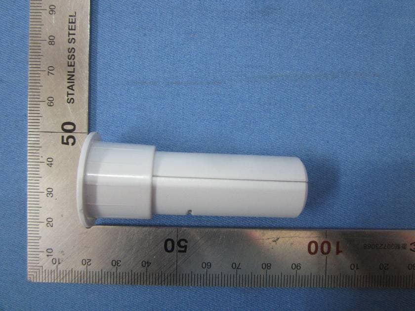
Aug 28, 2015Embedded Door Sensor
Equipment Class
DTS - Digital Transmission System
2AAP7ST880ZB
Aug 25, 2013OPTIMA US ZIGBEE THERMOSTAT
Equipment Class
DTS - Digital Transmission System