2AAP7ST880ZBOPTIMA US ZIGBEE THERMOSTAT
Salus Limited.
Click to zoom
Application Details
- Equipment Class
- DTS - Digital Transmission System
- Date of Grant
- Aug 25, 2013
- Application Purpose
- Original Equipment
- Date of Application
- Aug 25, 2013
- Equipment Note
- OPTIMA US ZIGBEE THERMOSTAT
- Frequency Range
- 2405.00000000 - 2480.00000000
- Company
- Salus Limited.
- Country
- China
Documents & Files
Document Text
Text extracted from the exhibit documents filed with the FCC. Open a document above to read the original.
Users Manual
ST880ZB / Optima USA Rev. 3.9 Form No. : F-ENG-1023A Page 1 of 38 Product Specification 1, Features Type: 7 days programmable thermostat For heating and cooling, heat pump and non-heat pump system With Ecofactor communication Equipment compatibility: Heat pump: 3H2C Non-heat pump: 2H2C System control: Heating, Cooling, Off, Emergency heating and Auto season changeover Fan control: Auto and On LCD: Segmented, positive. Blue backlight Input: Capacitive sensing “Touch Dial” Temperature measurement: Internal temperature sensor, Fahrenheit or Celsius selectable. Relative humidity measurement: Internal humidity sensor (internal use only, user not accessible) Clock: 12/24 hours with calendar. DST and Time zone selections. Program: 7 days programmable, 6 programs per day, individual heating and cooling setpoints. Program holds: Temporary, Permanent, Vacation and Duration (Duration through network only) Auto recovery Yes, user selectable. Filter warning: Yes, user selectable. HP Fault warning: Yes, LCD. AUX indicator: Yes, LCD. Key lock: Yes, software. Memory back up: Yes, Flash or EEPROM. Memory hold up time: 10 hours. Power supply: Dual power. Can operate on 2 AA cells or 24VAC, or both. Battery life: 18 months. Communication: Ecofactor, iControl, OTA software upgrade through Zigbee gateway. Internet connectivity via gateway with iControl server and iControl smartphone apps/Webapps Housing design: 107 x 107 x 28.5mm. Use wall mounting bracket. Thermostat can be removed from the bracket that the wires connected to. Material: PC241R. Texture: High glossy. Color: Optima white. IP30 Rohs Yes. ST880ZB / Optima USA Rev. 3.9 Form No. : F-ENG-1023A Page 2 of 38 2, Specification Equipment compatibility Heat pump system: 3 heating stages: Y1, Y2 and W1 (auxiliary heating) 2 cooling stages: Y1 and Y2 Emergency heating: W1 Reverse valve type O or B selectable Emergency heating HE/HG type selectable Heat pump fault feedback (L) indication Non heat pump system: 2 heating stages: W1 and W2 2 cooling stages: Y1 and Y2 HE/HG selectable Jumper for separated heating and cooling circuit Terminals Number of terminals: 9 + 1 (reserved for future) Terminals for heat pump Y1, Y2, W1, G, O/B, L, Rc, C Terminals for non heat pump Y1, Y2, W1, W2, G, Rc, Rh, C User interface Display: Segmented type LCD with blue backlight Input: Capacitive type “Touch Dial” Button: Hidden reset key Clock and Calendar Clock synchronization: via Internet. Clock free run accuracy: +/-2 seconds per day . Time display format: AM/PM / 24 hours format user selectable. DST: Enable / Disable user selectable. Clock automatically adjusted if DST is enabled. Time zone: -2 to +3 hours user selectable. Calendar: Valid through 2000 to 2099 Calendar display format: MM-DD-YY. (Calendar is not displayed on home screen) Temperature Measurement Temperature display format: Fahrenheit or Celsius user selectable. Temperature display range: Fahrenheit: 32°F ~ 99°F, 1°F display resolution Celsius: 0°C ~ 40°C, 1°C display resolution Temperature measurement accuracy: +/-0.5°C (15°C to 25°C room temperature) +/-1.0°C (full temperature measurement range) Calibration: Yes, via software, user adjustable. +/-7°F in 1°F resolution. +/-4°C in 0.5°C resolution. ST880ZB / Optima USA Rev. 3.9 Form No. : F-ENG-1023A Page 3 of 38 Relative humidity measurement Humidity display format: Percentage RH (Humidity data is only for thermostat internal use. It is displayed in test mode only. Humidity information is not available to end users.) Display / measurement range 20% ~ 95% in 1% resolution Humidity measurement accuracy: +/-8% at 60%, 25°C +/-10% full measurement range. Temperature Control Temperature setting range: (Program, Temporary hold and Permanent Hold) Heating and cooling: Fahrenheit: 41°F ~ 95°F, 1°F setting resolution Celsius: 5°C ~ 35°C, 1°C setting resolution Heating setpoint cannot be set higher than cooling in the same program. Temperature setting range: (Vacation hold) Heating only Fahrenheit: 32°F ~ 60°F, 1°F setting resolution Celsius: 0°C ~ 15°C, 1°C setting resolution Switching differential (span): Stage 1: Fahrenheit: 0.5°F, 1.0°F and 2.0°F user selectable. Celsius: 0.2°C, 0.5°C and 1.0°C user selectable. Stage 2: Fahrenheit: 2.0°F (fixed). Celsius: 1.0°C (fixed). Stage 3: Fahrenheit: 2.0°F (fixed). Celsius: 1.0°C (fixed). Auto season changeover deadband: Fahrenheit: 5°F ~ 11°F, 1°F setting resolution Celsius: 2.5°C ~ 6°C, 0.5°C setting resolution Temperature control accuracy: Base on NEMA test result: Span set to minimum. Total loading 2.5A. After control is stabilized, the following should be achieved: Differential: less than 2°F Droop: less than +/-1°F Control protection Compressor short cycle protection timer: 5 ~ 10 minutes, 1 minute setting resolution. Set through network. Residual Cooling fan delay timer: 30 ~ 300 seconds, 30 seconds setting resolution. Set through network. Auto heat cut-off: When room temperature is higher than 99°F or 35°C. Auto cool cut-off: When room temperature is lower than 40°F or 5°C. Temperature error cut-off: When error is found in room temperature measurement. Filter counter Filter counter: Counts Y1 or G turn on time for up to 999 hours. Filter change reminder: 300, 500 or 700 hours user selectable. Indication on LCD when Filter counter reached the reminder setting. ST880ZB / Optima USA Rev. 3.9 Form No. : F-E NG-1023A Page 4 of 38 Program Program style: 7-day programmable 6 programs per day Program time : Resolution: 10 minutes difference Shared between heating and cooling Program temperature: Resolution: 1°F or 1°C Individual heating and cooling setpoints Program override: 4 types: Temporary hold Permanent hold Vacation hold Duration hold (set through network only, no UI supports) Power Supply Power source: Dual power – Can be powered by Battery or 24VAC, or both. (For Heat pump mode, terminal C connection is required for L signal) Battery power: 2 AA size alkaline batteries 2 stages battery voltage monitor (low battery i…
Text truncated - open the document above for the full version.
Cover Letter(s)
Salus Limited. 9/F, Tower One, Lippo Centre, 89 Queensway, Hong Kong DATE :2013-8-20 Nemko Canada Inc 303 River Road Ottawa, Ontario, Canada K1V 1H2 Attn: Director of Certification Authority to Act as Agent On our behalf, I appoint Hans.Hu of Global United Technology Services Co., Ltd. 2nd Floor, Block No.2, Laodong Industrial Zone, Xixiang Road Baoan District Shenzhen Guangdong to act as our agent in the preparation of this application for equipment certification. I certify that submitted documents properly describe the device or system for which equipment certification is sought. I also certify that each unit manufactured, imported or marketed, as defined in the Federal Communications Commission’s regulations will have affixed to it a label identical to that submitted for approval with this application. For instances where our authorized agent signs the application for certification on our behalf, I acknowledge that all responsibility for complying with the terms and conditions for certification, as specified by Nemko Canada Inc, still resides with Salus Limited. and 9/F, Tower One, Lippo Centre, 89 Queensway, Hong Kong Dated this / Day of 8/20/2013 / Agency agreement expiration date: 8/20/2014 By: stanley ye Signature Printed Title: manager On behalf of : Salus Limited. Telephone: (86) 755 8473 6036-380
Cover Letter(s)
Differences Declaration To whom concern, We Salus Limited. hereby declares: The product model(s) are SAU10T1 identical in the same PCB layout, interior structure and electrical circuits with the model ST880ZB which tested in Global United Technology Services Co., Ltd., the only differences are the model name for commercial purpose. Authorized signature: Date: 2013-08- 20
Cover Letter(s)
Salus Limited. 9/F, Tower One, Lippo Centre, 89 Queensway, Hong Kong 2013-8-20 Equipment Autorisation Division Federal Communications Commission 7435 Oakland Mills Road Columbia, MD 21046 F CC ID: 2AAP7ST880ZB Product Name: OPTIMA US ZIGBEE THERMOSTAT Request for Confidentiality Pursuant to Sections 0.457 and 0.459 of the commissions rules, we hereby request that the following documents be held confidential: Schematics Block diagram Operational Description These materials contain trade secrets and proprietary information and are not customarily released to the public. The public disclosure of this information might be harmful to the company and provide unjustified benefits to our competitors. Dated this 8/20/2013 By: stanley ye Signature Printed Title: manager On behalf of : Salus Limited. Telephone: (86) 755 8473 6036-380
ID Label/Location Info
R ST880ZB RF Frequency: 2.45GHz Batteries: 3V AAX2 AC Power: 18~30 V AC Output: Max 1.0A per terminal Total max. 2.5A(all terminals) FCC ID: 2AAP7ST880ZB Made in China 64x23.8 mm 54DESAU10T110J68 光面贴纸+PP 4C
ID Label/Location Info
Label location
RF Exposure Info
FCC ID:2AAP7ST880ZB RF Exposure Evaluation Limits The criteria listed in the following table shall be used to evaluate the environment impact of human exposure to radio frequency (RF) radiation as specified in 1.1307(b) Limits for Maximum Permissible Exposure (MPE) Frequency range (MHz) Electric field strength (V/m) Magnetic field strength (A/m) Power density (mW/cm 2 ) Averaging time (minutes) (A) Limits for Occupational/Controlled Exposures 0.3–3.0 614 1.63 *(100) 6 3.0–30 1842/f 4.89/f *(900/f 2 ) 6 30–300 61.4 0.163 1.0 6 300–1500 f/300 6 1500–100,000 5 6 (B) Limits for General Population/Uncontrolled Exposure 0.3–1.34 614 1.63 *(100) 30 1.34–30 824/f 2.19/f *(180/f 2 ) 30 30–300 27.5 0.073 0.2 30 300–1500 f/1500 30 1500–100,000 1.0 30 f = frequency in MHz Friis transmission formula: Pd = (Pout*G)/(4*pi*r 2 ) Where Pd = power density in mW/cm 2 , Pout = output power to antenna in mW; G = gain of antenna in linear scale, Pi = 3.1416; R = distance between observation point and center of the radiator in cm Pd id the limit of MPE, 1 mW/cm 2 . If we know the maximum gain of the antenna and the total power input to the antenna, through the calculation, we will know the distance r where the MPE limit is reached. Test Procedure Software provided by client enabled the EUT to transmit and receive data at lowest, middle and highest channel individually. Test Result of RF Exposure Evaluation Frequency Output power to antenna (mW) Power Density at R=20cm (mW/cm 2 ) Limit (mW/cm 2 ) Result 2405MHz 33.574 0.00668 1.0 PASS 2440MHz 36.813 0.00732 1.0 PASS 2475MHz 34.198 0.00680 1.0 PASS 2480MHz 0.184 0.00004 1.0 PASS Remark: antenna gain=0 dBi
Test Report
Global United Technology Services Co., Ltd. Report No.: GTSE13070106001 Authorized Signature: Robinson Lo Laboratory Manager This report details the results of the testing carried out on one sample. The results contained in this test report do not relate to other samples of the same product and does not permit the use of the GTS product certification mark. The manufacturer should ensure that all products in series production are in conformity with the product sample detailed in this report. This report may only be reproduced and distributed in full. If the product in this report is used in any configuration other than that detailed in the report, the manufacturer must ensure the new system complies with all relevant standards. Any mention of GTS International Electrical Approvals or testing done by GTS International Electrical Approvals in connection with, distribution or use of the product described in this report must be approved by GTS International Electrical Approvals in writing. This document cannot be reproduced except in full, without prior written approval of the Company. Any unauthorized alteration, forgery or falsification of the content or appearance of this document is unlawful and offenders may be prosecuted to the fullest extent of the law. Unless otherwise stated the results shown in this test report refer only to the sample(s) tested and such sample(s) are retained for 90 days only.” FCC REPORT Applicant: Salus Limited. Address of Applicant: 9/F, Tower One, Lippo Centre, 89 Queensway, Hong Kong Equipment Under Test (EUT) Product Name: OPTIMA US ZIGBEE THERMOSTAT Model No.: ST880ZB, SAU10T1 FCC ID: 2AAP7ST880ZB Applicable standards: FCC CFR Title 47 Part 15 Subpart C Section 15.247:2012 Date of sample receipt: July 10, 2013 Date of Test: July 10-19, 2013 Date of report issued: July 19, 2013 Test Result : PASS * * In the configuration tested, the EUT complied with the standards specified above. Report No.: GTSE13070106001 Global United Technology Services Co., Ltd. Project No.: GTSE130701060RF 2nd Floor, Block No.2, Laodong Industrial Zone, Xixiang Road Baoan District, Shenzhen, China 518102 Telephone: +86 (0) 755 2779 8480 Fax: +86 (0) 755 2779 8960 Page 2 of 44 2 Version Version No. Date Description 00 July 19, 2013 Original Prepared By: Date: July 19, 2013 Project Engineer Check By: Date: July 19, 2013 Reviewer Report No.: GTSE13070106001 Global United Technology Services Co., Ltd. Project No.: GTSE130701060RF 2nd Floor, Block No.2, Laodong Industrial Zone, Xixiang Road Baoan District, Shenzhen, China 518102 Telephone: +86 (0) 755 2779 8480 Fax: +86 (0) 755 2779 8960 Page 3 of 44 3 Contents Page 1 COVER PAGE ...........................................................................................................................................1 2 VERSION .................................................................................................................................................. 2 3 CONTENTS .............................................................................................................................................. 3 4 TEST SUMMARY ..................................................................................................................................... 4 5 GENERAL INFORMATION ...................................................................................................................... 5 5.1 CLIENT INFORMATION......................................................................................................................... 5 5.2 GENERAL DESCRIPTION OF EUT ......................................................................................................... 5 5.3 TEST MODE........................................................................................................................................ 6 5.4 DESCRIPTION OF SUPPORT UNITS....................................................................................................... 6 5.5 TEST FACILITY.................................................................................................................................... 7 5.6 TEST LOCATION................................................................................................................................. 7 6 TEST INSTRUMENTS LIST ..................................................................................................................... 8 7 TEST RESULTS AND MEASUREMENT DATA...................................................................................... 9 7.1 ANTENNA REQUIREMENT:.................................................................................................................... 9 7.2 CONDUCTED EMISSIONS................................................................................................................... 10 7.3 CONDUCTED PEAK OUTPUT POWER.................................................................................................. 13 7.4 CHANNEL BANDWIDTH...................................................................................................................... 16 7.5 POWER SPECTRAL DENSITY............................................................................................................. 19 7.6 BAND EDGES.................................................................................................................................... 22 7.6.1 Conducted Emission Method ..................................................................................................... 22 7.6.2 Radiated Emission Method ........................................................................................................24 7.7 SPURIOUS EMISSION......................................................................................................................... 27 7.7.1 Conducted Emission Method ..................................................................................................... 27 7.7.2 Radiated Emission …
Text truncated - open the document above for the full version.
Test Setup Photos
Radiated Emission Conducted Emission
Contact Information
Applicant
stanley ye(manager)
Test Firm
Global United Technology Service Co., LtdRobinson Lo
Technical Specifications
| # | Rule Parts | Frequency Range | Power Output |
|---|---|---|---|
| 1 | 15C | 2.40 GHz - 2.48 GHz | 36.80 mW |
Other Applications from Salus Limited.
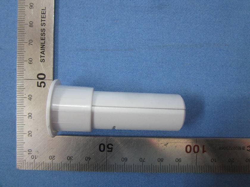
2AAP7-SS881ZB
Aug 28, 2015Embedded Door Sensor
Equipment Class
DTS - Digital Transmission System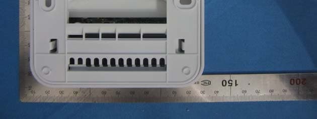
2AAP7SAU1AT1
Apr 29, 2014Optima 900MHz USA
Equipment Class
DXX - Part 15 Low Power Communication Device Transmitter