2AASBHERAQ4029Cellular Router with WiFi
Eseye Design Limited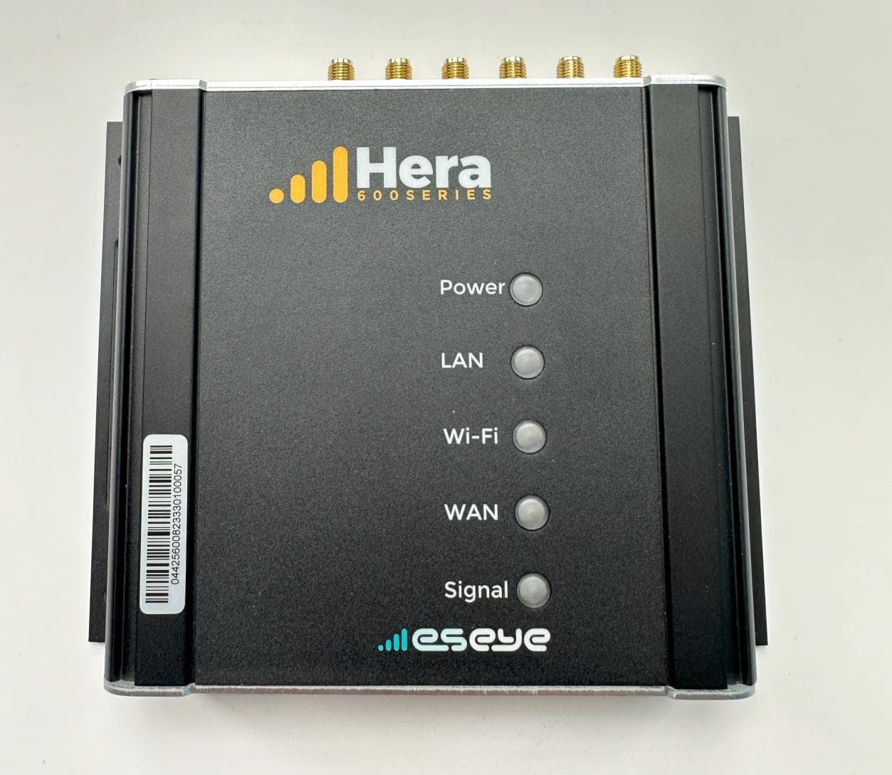
Click to zoom
Application Details
- Equipment Class
- DTS - Digital Transmission System
- Date of Grant
- Apr 22, 2026
- Application Purpose
- Original Equipment
- Equipment Note
- Cellular Router with WiFi
- Frequency Range
- 2412.00000000 - 2462.00000000
- Company
- Eseye Design Limited
- Country
- United Kingdom
Documents & Files
Document Text
Text extracted from the exhibit documents filed with the FCC. Open a document above to read the original.
Users Manual
Getting started The Hera is designed for wall-mounting. Choosing a location Locate the Hera in a weather-protected, stable, vibration-free environment. • Operating temperature: -20°C to +55°C (-4°F to 131°F) • Relative humidity: 5-95%, non-condensing Wall-mounting the Hera 1. If a SIM card is supplied, ensure it is fully inserted in the Hera. 2. If required, fit the SIM security plate (see below). 3. Measure the template overleaf to ensure it is accurate, as the printing process may distort it. 4. If the template is accurate, fix the page to the wall using the spirit level and masking tape. Alternatively, use the Hera to mark the drill holes. 5. Drill holes and prepare them with the wall plugs/anchors. 6. Attach the cellular cables (LTE 1 and LTE 2) and WiFi antennas to the Hera. 7. Mount the Hera on the wall using the recommended fixings. 8. Position all antennas for optimal performance. 9. Insert the power connector. 10. Plug the mains adaptor into a dedicated socket, then switch on. 11. Ensure all cables and antennas are securely anchored to avoid intermittent connection problems. 12. Configure the Hera using the supplied web user interface. For more information, see How to connect to the Hera below. Fitting the SIM card security plate • Use a Security Torx screwdriver (T10 tip) to fit the security plate across the Hera SIM card slots. How to connect to the Hera Connect to the Hera with an Ethernet cable or over WiFi. Eseye may include a unique Configuration Information Sheet with each Hera Series Router. Use this information to connect, log into, and configure the Hera. If the sheet is not included, your service provider or reseller will advise you of the contents. Connect using an Ethernet (wired) connection • Use an Ethernet cable to connect from the Hera Ethernet port Link2 to a PC or laptop, either directly or via an Ethernet switch. Connect using WiFi If there is no SSID information supplied, use a wired connection to the Hera Series Router. 1. Ensure the Hera WiFi LED is illuminated. 2. Search wireless networks on your WiFi-enabled device. Connect to the network that matches the SSID. 3. At the prompt, type the WiFi username and passphrase exactly as supplied. Logging in to the Hera Series Router 1. Using a browser on your device, type the supplied Web Interface IP into the address bar. For example: http://192.168.0.1 2. Press return. 3. At the prompt, enter the supplied credentials, then select OK. The Hera Series Router web interface appears. Configuring the cellular connection The Hera is preconfigured to connect to a cellular network using an Eseye AnyNet SIM. Warranty • Use only Eseye-approved mains power adaptors. Using the Hera with any other mains power adaptor will invalidate the warranty. • Do NOT open the casing under any circumstances, as it will invalidate the warranty. There are no user-serviceable components inside the Hera. If a fault develops with the product, contact your service provider or reseller. • Only manufacturer-authorised personnel may replace the Hera batteries. This ensures fitting of approved parts, and fully complies with Battery Directive 91/157/EEC and local legislation regarding responsible recycling and correct disposal. Failure to comply will invalidate the warranty. • Take all reasonable precautions when choosing the site and installing the Hera. Read and understand all warnings and installation instructions. Eseye Design are not liable for consequential loss or damage that occurs because the warnings and installation instructions in this guide were not followed. • Do not insert or remove a SIM card when the Hera is powered on. This will cause problems with the Hera functionality. Always power off before inserting or removing a SIM card. Warnings Keep away from direct sunlight. Do not place the unit close to a heat source (such as other electrical equipment). Do not enclose the unit in unventilated housing, where heat may accumulate. The supplied antennas are not for outdoor use. If using an outdoor antenna, ensure it provides adequate lightning protection. Avoid locations exposed to heavy soiling, such as exhaust from machinery, liquid or airborne particles from industrial processes, or excessive dust. Locate the Hera within 1 metre of a mains power outlet. Use only an approved Limited Power Source (LPS) mains adaptor compliant with IEC/UL 60950-1 or IEC/UL 62368-1. Using an unapproved power adaptor will invalidate the warranty and the Hera regulatory approval, and may damage the unit. Do not modify the mains power adaptor. A falling device can cause injury. Do not mount more than 2 metres above the floor. The Hera uses radio signals and cellular networks, and is not guaranteed to connect in all possible conditions. Never rely solely upon any wireless device for life-critical communications. Position cellular antennas at least one metre away from people in normal operation. The Hera incorporates a GSM radio module, which receives and transmits radio frequency (RF) energy when powered on. Never install your Hera where prohibited, or if it may cause interference or danger. When installing in healthcare facilities, observe on site mobile phone usage restrictions, as some medical equipment may be sensitive to RF energy. This includes implanted medical equipment, such as cardiac pacemakers and hearing aids. We recommend testing for interference before installing the Hera permanently. Post a clear, visible warning alongside the Hera to inform people with medical implants of the potential danger of radio frequency interference. RF energy may interfere with TV sets; radios; computers; and inadequately shielded equipment if the Hera is in close proximity. Do not operate GSM equipment, including the Hera, on aircraft, in order to prevent interference with communications systems. Offenders may have their cellular services suspended or banned, and may also face legal action. Do not operate the Hera in the presence of flammable gases, fumes, or potenti…
Text truncated - open the document above for the full version.
Attestation Statements
Global Head Office. Eseye Design Limited. 20 Nugent Road, Guildford, GU2 7AF. UK Telephone: +44 (0) 1483 802501 | Email: [email protected] | www.eseye.com Eseye, AnyNet, AnyNet Secure and Eseye Logos are registered trademarks of Eseye Ltd © 2023. All Rights Reserved | Reg No. 4641762| VAT No. 830471842 | Classification: Company Confidential 04/21/2026 Federal Communications Commission 7435 Oakland Mills Road Columbia, MD 21046 USA Subject: CFR 47 §2.911 (d)(5) Attestation Applicant: Eseye Design Limited FCC ID: 2AASBHERAQ4029 Model number/name: Hera604v6 To whom it may concern 1. The applicant certifies that the equipment for which authorization is sought is not “covered” equipment prohibited from receiving an equipment authorization pursuant to section 2.903 of the FCC rules. 2. The applicant certifies that the equipment does not have cybersecurity and / or anti-virus software produced or provided by Kaspersky Lab, Inc. or any of its successors and assignees, identified on the Covered List installed on the device, nor will it be installed by the applicant anytime after certification. 3. The applicant certifies that the equipment is a router “produced in a foreign country” but that it does not fall within the scope of the National Security Determination on the Threat Posed by Routers Produced by Foreign Countries published March 20, 2026 as clarified by the FCC FAQ. 4. The applicant certifies that, as of the date of the filing of the application, the applicant is not identified on the Covered List as an entity producing “covered” equipment and is not an affiliate or subsidiary of an entity identified on the Covered List. Sincerely yours, Name: Jon Darley Job Title: Direct of Things Company Name: Eseye Design Limited
Attestation Statements
Global Head Office. Eseye Design Limited. 20 Nugent Road, Guildford, GU2 7AF. UK Telephone: +44 (0) 1483 802501 | Email: [email protected] | www.eseye.com Eseye, AnyNet, AnyNet Secure and Eseye Logos are registered trademarks of Eseye Ltd © 2023. All Rights Reserved | Reg No. 4641762| VAT No. 830471842 | Classification: Company Confidential 16 th October 2025 Federal Communications Commission 7435 Oakland Mills Road Columbia, MD 21046 USA Subject: CFR 47 §2.911 (d)(7) Agent Designation Attestation Applicant: Eseye Design Limited FCC ID: 2AASBHERAQ4029 Model number/name: Hera604v6 To whom it may concern The applicant as required by section 2.911(d)(7), designates the following agent, located in the United States, for purposes of acting as the applicant’s agent for service of process. U.S. Agent for service of process information: Eseye LLC FRN: 0037572310 Gabrielle Curry 5229 College St NW Albuquerque, NM 87120 [email protected] The applicant acknowledges that they will maintain an agent for no less than one year after the grantee has terminated all marketing and importation or the conclusion of any Commission-related proceeding involving the equipment. The applicant further acknowledges their responsibility to inform the FCC whenever the agent information changes. Sincerely yours, Name: Jon Darley Job Title: Director of Things
Attestation Statements
Global Head Office. Eseye Design Limited. 20 Nugent Road, Guildford, GU2 7AF. UK Telephone: +44 (0) 1483 802501 | Email: [email protected] | www.eseye.com Eseye, AnyNet, AnyNet Secure and Eseye Logos are registered trademarks of Eseye Ltd © 2023. All Rights Reserved | Reg No. 4641762| VAT No. 830471842 | Classification: Company Confidential 10/16/2025 Federal Communications Commission 7435 Oakland Mills Road Columbia, MD 21046 USA Subject: CFR 47 §2.911 (d)(7) FCC US Agent Letter of Attestation Applicant: Eseye Design Limited FCC ID: 2AASBHERAQ4029 Model number/name: Hera604v6 To whom it may concern This letter is to confirm that we have accepted the responsibility to act as US Agent on behalf of the above applicant for the above referenced FCC ID. U.S. Agent for service of process information: Eseye LLC FRN: 0037572310 Gabrielle Curry 5229 College St. NW Albuquerque, NM 87120 [email protected] We are aware of the requirements and responsibilities of the applicant’s agent for service of process as outlined in the FCC section 2.911(d)(7) and Report and Order FCC 22-84 paragraph 63. Sincerely yours, Name: Gabrielle Curry(agent) Job Title: Customer Success Manager (agent)
Cover Letter(s)
Global Head Office. Eseye Design Limited. 20 Nugent Road, Guildford, GU2 7AF. UK Telephone: +44 (0) 1483 802501 | Email: [email protected] | www.eseye.com Eseye, AnyNet, AnyNet Secure and Eseye Logos are registered trademarks of Eseye Ltd © 2023. All Rights Reserved | Reg No. 4641762| VAT No. 830471842 | Classification: Company Confidential 5 th July 2024 Telecommunication Certification Body UL International (UK) Ltd Units 1-4, Horizon Wade Road Kingsland Business Park Basingstoke Hampshire RG24 8AH United Kingdom Subject: Authorisation Letter To whom it may concern This is to certify that Eseye Design Limited hereby authorises UL International (UK) Ltd. to act as the TCB for the application of the Hera604v6, FCC ID: 2AASBHERAQ4029 to the FCC. We certify that we are not subject to a denial of Federal benefits, that include FCC benefits, pursuant to Section 5301 of the Anti-Drug Abuse Act of 1988, 21 U.S.C. § 862 because of a conviction for possession or distribution of a controlled substance. See 47 CFR 1.2002(b) for the definition of a "party" for these purposes. We also acknowledge that the FCC operates a certification scheme that makes some documentation (information) accessible to the public in accordance with FCC KDB publication 726920 D01. This is information that is generally known to the public. Yours faithfully, Jon Darley Director of Things
Cover Letter(s)
Global Head Office. Eseye Design Limited. 20 Nugent Road, Guildford, GU2 7AF. UK Telephone: +44 (0) 1483 802501 | Email: [email protected] | www.eseye.com Eseye, AnyNet, AnyNet Secure and Eseye Logos are registered trademarks of Eseye Ltd © 2023. All Rights Reserved | Reg No. 4641762| VAT No. 830471842 | Classification: Company Confidential 16 nd October 2025 Telecommunication Certification Body UL International (UK) Ltd Units 1-4, Horizon Wade Road Kingsland Business Park Basingstoke Hampshire RG24 8AH United Kingdom Subject: Permanent Confidentiality Request Certification Application FCC ID: 2AASBHERAQ4029 To whom it may concern Pursuant to Sections 0.457(d) and 0.459 of CFR 47, Eseye Design Limited request that the following information, provided to support the FCC application for the Hera604v6, FCC ID: 2AASBHERAQ4029 be held permanently confidential: Schematics Parts List / BoM Block Diagrams Operational Description Tune Up document Software Security The above material contains trade secrets not customarily released to public that are judged to have the potential to cause detriment to the applicant and provide unjustified benefits to its competitors. This information should not be available for public disclosure for an indefinite period of time. Yours faithfully Jon Darley Director of Things
External Photos
Hera604v6 External Photographs Figure 1: Hera604v6 Cased (Top) Figure 2: Hera604v6 Cased (bottom) Figure 3: Hera604v6 Cased (left) Figure 4: Hera604v6 Cased (right) Figure 5: Hera604v6 bottom panel (from top) Figure 6: Hera604v6 bottom panel (from bottom) Figure 7: Hera604v6 top panel (from top) Figure 8: Hera604v6 top panel (from bottom)
ID Label/Location Info
Scale 1:1 Dimensions in mm Corners rounded Max radius 5mm Construction of RoW regional approval label Material: Silver finish Polyester or equivalent Suitable for thermal transfer ribbon printing Self adhesive backed, Acrylic emulsion or equivalent The label must not blacken or discolour with exposure to heat or sunlight. Temp range: -20 +80C Thermal transfer printing must withstand the IEC 62368 rub test. TITLE SIZE DRAWN APP DRAWING NUMBER REV A4 JJvdB © SHEET 1 OF 2 1.10 02/07/2024 H604v6 RoW Regional Approval Label MLBLVN0037 Eseye Design Limited 20 Nugent Road, Surrey Research Park Guildford, Surrey, GU2 7AF, UK Tel: +44 (0)1483 802 501 a bc 1:1 Scale example If any details are in doubt, please contact Eseye Design for clarification. a. Artwork; left aligned in block a (20.5mm x 8.3mm): Block a overlaps with block b Artwork for symbols, scale 1:1 converted to curves Eseye Design Limited can supply this artwork in various formats d. Text Arial Narrow; 5pt; left aligned in block d (47mm x 10.5mm): This device complies with part 15 of the FCC Rules. Operation is subject to the following two conditions: 1.This device may not cause harmful interference. 2.This device must accept any interference received, including interference that may cause undesired operation. c. Text Arial Narrow; 6pt; include leading space (represented by the interpunct "·" below); left aligned in block c (19.5mm x 13.5mm): ·H604V6 ·EPCB256003 ·2AASBHERAQ4029 ·11329A-HERAQ4029 ·N7NEM75T ·2417C-EM75T b. Text Arial Narrow Bold; 6pt; include trailing space (represented by the interpunct "·" below); right aligned in block b (15mm x 13.5mm): Model:· HVIN:· FCC ID:· IC:· Contains FCC ID:· Contains IC:· d H604V6 EPCB256003 2AASBHERAQ4029 11329A-HERAQ4029 N7NEM75T 2417C-EM75T Model: HVIN: FCC ID: IC: Contains FCC ID: Contains IC: This device complies with part 15 of the FCC Rules. Operation is subject to the following two conditions: 1.This device may not cause harmful interference. 2.This device must accept any interference received, including interference that may cause undesired operation. 88.5 mm 80.2 mm 64.5 mm 90.0 mm 50.0 mm Application of regional approval label The regional label will be applied in 1 locations per product: On the rear of product, centered vertically as to the right 16 mm 106 mm 20 mm 83 mm TITLE SIZE DRAWN APP DRAWING NUMBER REV A4 JJvdB © SHEET 2 OF 2 1.10 02/07/2024 MLBLVN0037 Eseye Design Limited 20 Nugent Road, Surrey Research Park Guildford, Surrey, GU2 7AF, UK Tel: +44 (0)1483 802 501 H604v6 RoW Regional Approval Label
Internal Photos
Figure 1: Hera604v6 PCB Top Figure 2a: Hera604v6 PCB Top (close up) Figure 3b: Hera604v6 PCB Top (close up) – label removed Figure 2c: Hera604v6 PCB Top (close up) Figure 2d: Hera604v6 PCB Top (close up) Figure 2e: Hera604v6 PCB Top (close up) Figure 2f: Hera604v6 PCB Top (close up) Figure 2g: Hera604v6 PCB Top (close up) Figure 3: Hera604v6 PCB Top with WiFi Sheild Fitted Removed Figure 3a: Hera604v6 PCB Top with WiFi Sheild Fitted Removed (close up) Figure 4: Hera604v6 PCB Bottom Figure 4a: Hera604v6 PCB Bottom (close up) Figure 4b: Hera604v6 PCB Bottom (close up) Figure 4c: Hera604v6 PCB Bottom (close up) Figure 4d: Hera604v6 PCB Bottom (close up) Figure 4e: Hera604v6 PCB Bottom (close up) Figure 4f: Hera604v6 PCB Bottom (close up) Figure 5: Hera604v6 PCB Bottom (Thermal Transfer Can removed) Figure 5a: Hera604v6 PCB Bottom (Thermal Transfer Can removed close up)
RF Exposure Info
UL International (UK) Ltd Unit 1-4, Horizon, Wade Road, Kingsland Business Park, Basingstoke, Hampshire, RG24 8AH, UK T: +44 (0)1256 312000 W: www.ul.com RF EXPOSURE EVALUATION REPORT FROM UL For: Eseye Design Ltd Product: Hera604v6 FCC ID: 2AASBHERAQ4029 Contains FCC ID: N7NEM75T RF Exposure Evaluation Report Serial No.: UL/REGA2/14647518.31 This RF Exposure Evaluation Report Is Issued Under The Authority Of Andrew Hoare, Head of Certification: pp Written By: Marc Schmidt Checked By: Ernest Cheung Report Copy No: PDF01 Issue Date: 22 April 2026 This report may be reproduced in full. Partial reproduction may only be made with the written consent of UL. UL Solutions RF EXPOSURE EVALUATION REPORT No: UL/REGA2/14647518.31 Page: 2 of 8 Issue Date: 22 April 2026 For: Eseye Design Ltd Product: Hera604v6 This page has been left intentionally blank. UL Solutions RF EXPOSURE EVALUATION REPORT No: UL/REGA2/14647518.31 Page: 3 of 8 Issue Date: 22 April 2026 For: Eseye Design Ltd Product: Hera604v6 Table of Contents 1. Client Information ........................................................................................................... 4 2. Description Of The Apparatus And Its Operational Environment ............................... 4 3. Equipment Specifications .............................................................................................. 5 4. Methods and Procedures ............................................................................................... 6 5. Calculations .................................................................................................................... 7 6. Conclusion ...................................................................................................................... 8 UL Solutions RF EXPOSURE EVALUATION REPORT No: UL/REGA2/14647518.31 Page: 4 of 8 Issue Date: 22 April 2026 For: Eseye Design Ltd Product: Hera604v6 1. Client Information Company Name: Eseye Design Ltd Address: 20 Nugent Road Surrey Research Park Guildford GU2 7AF United Kingdom Contact Name: Jon Darley 2. Description Of The Apparatus And Its Operational Environment Model / Type Reference: Hera604v6 Basic Direct Function: Cellular Router with WiFi Intended Operating Environment: Indoors The Hera604v6 operates in the 2.4 GHz frequency band (WLAN 802.11b/g/n), 5 GHz frequency band (WLAN 802.11a/n/ac) using cellular WCDMA/LTE technologies. The Hera604v6 uses integrated certified modules: - Cellular FCC ID: N7NEM75T UL Solutions RF EXPOSURE EVALUATION REPORT No: UL/REGA2/14647518.31 Page: 5 of 8 Issue Date: 22 April 2026 For: Eseye Design Ltd Product: Hera604v6 3. Equipment Specifications Equipment Category: 2.4 GHz WLAN / 5 GHz WLAN / Cellular WCDMA/LTE Type of Unit: Router Operating Frequency Range: 2.4GHz WLAN 5GHz WLAN WCDMA 2 WCDMA 4 WCDMA 5 LTE B2 LTE B4 LTE B5 LTE B7 LTE B12 LTE B13 LTE B14 LTE B25 LTE B26 LTE B41 LTE B48 LTE B66 LTE B71 2412 – 2462 MHz 5180 – 5700 MHz 1850 – 1910 MHz 1710 – 1755 MHz 824 – 849 MHz 1850 – 1910 MHz 1710 – 1755 MHz 824 – 849 MHz 2500 – 2570 MHz 699 – 716 MHz 777 – 787 MHz 788 – 798 MHz 1850 – 1915 MHz 814 – 849 MHz 2496 – 2690 MHz 3550 – 3700 MHz 1710 – 1780 MHz 663 – 698 MHz *RF Output Power (max. dBm): WLAN 2.4GHz WLAN 5GHz WCDMA/LTE 12.5 (per chain) 18.0 (per chain) 24.0 *Antenna Gain (max. peak values dBi): WLAN 2.4GHz WLAN 5GHz LTE 4.0 4.0 4.0 EIRP (max. dBm): WLAN 2.4GHz WLAN 5GHz WCDMA/LTE 16.5 (SISO) / 19.51 (2x2 MIMO) 22.0 (SISO) / 25.01 (2x2 MIMO) 28.0 * Specification values have been supplied by the manufacturer. The maximum power and maximum antenna gain will be used in the calculations, as these will show worst case. 2.4GHz WLAN + 5GHz WLAN + Cellular WCDMA/LTE can operate simultaneously UL Solutions RF EXPOSURE EVALUATION REPORT No: UL/REGA2/14647518.31 Page: 6 of 8 Issue Date: 22 April 2026 For: Eseye Design Ltd Product: Hera604v6 4. Methods and Procedures Reference: KDB 447498 D01 v06 Title: RF Exposure Procedures and Equipment Authorisation Policies for Mobile and Portable Devices Reference: FCC §1.1310 Title: Radiofrequency radiation exposure limits UL Solutions RF EXPOSURE EVALUATION REPORT No: UL/REGA2/14647518.31 Page: 7 of 8 Issue Date: 22 April 2026 For: Eseye Design Ltd Product: Hera604v6 5. Calculations 5.1 MPE The MPE calculation to calculate the safe operating distance for the user is. S = EIRP/(4 * π * R 2 ) Where S = Power density EIRP = Effective Isotropic Radiated Power R = distance to the centre of radiation of the antenna (safe operating distance) Power Density Requirement From table 1 (ii) - Limits for General Population/ Uncontrolled Exposure of FCC §1.1310 (1)(e) for f >1500MHz, S req = 1.0 mW/cm 2 From table 1 (ii) - Limits for General Population/ Uncontrolled Exposure of FCC §1.1310 (1)(e) for f = 300 - 1500MHz, S req = f/1500 mW/cm 2 (f = operating frequency in MHz) Note: the worst-case limit has been used for all Cellular bands VALUES Frequency Range (MHz) Operating Band EIRP (dBm) EIRP (mW) Power Density S mw/ cm 2 Limit S req Calculated S n @ 20cm S n /S req 2412 – 2462 WLAN 19.51 89.3 1.00 0.018 0.018 5180 – 5700 WLAN 25.01 317.0 1.00 0.063 0.063 824 – 849 3G 1 28.0 631.0 0.55 0.126 0.229 663 – 698 4G 1 28.0 631.0 0.44 0.126 0.286 NOTE 1: Lowest frequency used as this gives the worst-case limit value. UL Solutions RF EXPOSURE EVALUATION REPORT No: UL/REGA2/14647518.31 Page: 8 of 8 Issue Date: 22 April 2026 For: Eseye Design Ltd Product: Hera604v6 5.2 KDB447498 D01 v06 Section 7.2 SIMULTANEOUS TRANSMISSION CONSIDERATIONS For simultaneous transmission: As per KDB, summation of calculated MPE ratios (worst case): ΣMPE ratios = (S 1 /S req1 ) + (S 2 /S req2 ) + (S 4 /S req4 ) = 0.018 + 0.063 + 0.286 = 0.367 Σ of MPE ratios<1.0, so in accordance with KDB447498 D01 V06 Section 7.2, simultaneous transmission test exclusion applies for the transmitters. 6. Conclusion The required 20cm RF exposure limits for General Population/Uncontrolled Exposure will not be exceeded for the Hera604v6.
Test Report
UL INTERNATIONAL GERMANY GMBH Hedelfinger Str. 61 70327 Stuttgart, Germany [email protected] TEST REPORT Test Report No.: UL-RPT-RP-14647518-1316-FCC Applicant * : Eseye Design Limited Model No. * : Hera604v6 FCC ID * : 2AASBHERAQ4029 Technology * : WLAN 2.4 GHz (802.11 b, g, n) Test Standard(s) : FCC Parts 15.207, 15.209(a) & 15.247 For details of applied tests refer to test result summary 1. This test report shall not be reproduced in full or partial, without the written approval of UL International Germany GmbH. 2. The results in this report apply only to the sample tested. 3. The test results in this report are traceable to the national or international standards. 4. Test Report Version 1.1 supersede Version 1.0 with immediate effect Test Report UL-RPT-RP-14647518-1316-FCC Version 1.1 issue date 20 February 2026 Replaces Test Report UL-RPT-RP-14647518-1316-FCC Version 1.0 issue date 22 May 2024 which is no longer valid. 5. Result of the tested sample: Pass 6. All information marked with a (*) were provided by customer / applicant or authorized representative ______________________________ ______________________________ Prepared by: Rachid Acharkaoui Approved by Bernd Woerl Title: Operation Manager Title: Staff Laboratory Engineer Date: 20 Feb 2026 Date: 20 Feb 2026 This laboratory is accredited by DAkkS. The tests reported herein have been performed in accordance with its’ terms of accreditation. UL INTERNATIONAL GERMANY GMBH TEST REPORT NO: UL-RPT-RP-14647518-1316-FCC TEST REPORT VERSION 1.1 ISSUE DATE: 20 FEB 2026 Page 2 of 63 FCC 15.247 WLAN-Template Version 2.0 This page has been left intentionally blank. UL INTERNATIONAL GERMANY GMBH TEST REPORT NO: UL-RPT-RP-14647518-1316-FCC TEST REPORT VERSION 1.1 ISSUE DATE: 20 FEB 2026 Page 3 of 63 FCC 15.247 WLAN-Template Version 2.0 Table of Contents 1. Customer Information * ........................................................................................................... 4 1.1. Applicant Information 4 1.2. Manufacturer Information 4 2. Summary of Testing ................................................................................................................. 5 2.1. General Information 5 Applied Standards 5 Location 5 Date Information 5 2.2. Summary of Test Results 6 2.3. Methods and Procedures 6 2.4. Deviations from the Test Specification 6 3. Equipment Under Test (EUT) .................................................................................................. 7 3.1. Identification of Equipment Under Test (EUT) * 7 3.2. Description of EUT * 7 3.3. Modifications Incorporated in the EUT 7 3.4. Additional Information Related to Testing * 8 3.5. Support Equipment 9 A. Support Equipment (In-house) 9 B. Support Equipment (Manufacturer supplied) * 9 4. Operation and Monitoring of the EUT during Testing ......................................................... 10 4.1. Operating Modes 10 4.2. Configuration and Peripherals 10 5. Measurements, Examinations and Derived Results ............................................................ 12 5.1. General Comments 12 5.2. Test Results 13 5.2.1. Transmitter AC Conducted Spurious Emissions 13 5.2.2. Transmitter Minimum 6 dB Bandwidth 21 5.2.3. Transmitter Duty Cycle 26 5.2.4. Transmitter Power Spectral Density 30 5.2.5. Transmitter Maximum (Peak) Output Power 35 5.2.6. Transmitter Radiated Emissions 40 5.2.7. Transmitter Band Edge Radiated Emissions 50 6. Measurement Uncertainty ..................................................................................................... 60 7. Used equipment ..................................................................................................................... 61 8. Report Revision History ........................................................................................................ 63 UL INTERNATIONAL GERMANY GMBH TEST REPORT NO: UL-RPT-RP-14647518-1316-FCC TEST REPORT VERSION 1.1 ISSUE DATE: 20 FEB 2026 Page 4 of 63 FCC 15.247 WLAN-Template Version 2.0 1. Customer Information * 1.1. Applicant Information Company Name: Eseye Design Limited Company Address: 20 Nugent Road, Guildford, GU2 7AF Contact Person: Jon Darley Contact E-Mail Address: [email protected] Contact Phone No.: +44 1483 802 503 1.2. Manufacturer Information Company Name: Eseye Design Limited Company Address: 20 Nugent Road, Guildford, GU2 7AF Contact Person: Jon Darley Contact E-Mail Address: [email protected] Contact Phone No.: +44 1483 802 503 UL INTERNATIONAL GERMANY GMBH TEST REPORT NO: UL-RPT-RP-14647518-1316-FCC TEST REPORT VERSION 1.1 ISSUE DATE: 20 FEB 2026 Page 5 of 63 FCC 15.247 WLAN-Template Version 2.0 2. Summary of Testing 2.1. General Information Applied Standards Specification Reference: 47CFR15.247 Specification Title: Code of Federal Regulations Volume 47 (Telecommunications): Part 15 Subpart C (Intentional Radiators) - Section 15.247 Specification Reference: 47CFR15.207 and 47CFR15.209 Specification Title: Code of Federal Regulations Volume 47 (Telecommunications): Part 15 Subpart C (Intentional Radiators) - Sections 15.207 and 15.209 Location Location of Testing: UL International Germany GmbH; Admiral-Rosendahl-Strasse 9 63263 Neu-Isenburg, GERMANY Registration Number: 399704 Date Information Order Date: 10 January 2023 EUT arrived: 20 November 2023 Test Dates: 21 February 2024 to 04 March 2024, 09 Feb 2026 (for V1.1 retesting) EUT returned: -/- UL INTERNATIONAL GERMANY GMBH TEST REPORT NO: UL-RPT-RP-14647518-1316-FCC TEST REPORT VERSION 1.1 ISSUE DATE: 20 FEB 2026 Page 6 of 63 FCC 15.247 WLAN-Template Version 2.0 2.2. Summary of Test Results DIGITAL TRANSMISSION SYSTEMS (DTS): 2400-2483.5 MHz FCC Part 15 Clause Compliance Test Description Test Result C N.C. N.P. N.A. 15.207 Transmitter AC Power Line Conducted Emissions ☒ ☐ ☐ ☐ Part 15.247(a)(2) Transmitter Minimum 6 dB Bandwidth ☒ ☐ ☐ ☐ Part 15.35(c) Transmitter Duty Cycle (Note 1) ☒ ☐ ☐ ☐ Part 15.247(e) Transmitter Power Spectral Density ☒ ☐ ☐ ☐ Part 15.247(b)(3) Transmitter …
Text truncated - open the document above for the full version.
Test Report
Product Number: AN2450-5505BRS Product Name: Antenna Page 1 Specification For Approval Date: 2014/ 03 /19 File No.: 131105005 Version: 1.0 Customer: 宇智網通科技股份有限公司 Customer P/N: / INVAX P/N: AN2450-5505BRS Description : Antenna Cortec Checked By: Customer Approved By: INVAX System Technology Corp. Cortec Technology Inc. 4F. No. 815.Chung Hsiao East Rd.,Sec.5 Xian-Xi Industrial, Sha-Tou Administration Zone, Taipei, TAIWAN Chang-An Town, Dong-Guan City, Guangdong Province, China TEL:886-2-2788-5218 FAX:886-2-2783-1658 TEL:86-769-85388261 FAX:86-769-85317869 htt p://www.invaxsystem.com http://www.cortec.com.cn Product Number: AN2450-5505BRS Product Name: Antenna Page 2 Index: 1. Revision History / Page 3 2. Specification / Page 4 3. Characteristics and Reliability Test / Page 5 4. Antenna - S Parameter Test Data / Page 6 5. Antenna - Radiation Pattern Test Data / Page 7 6. Mechanical and Packing Drawing / Page 8 ~ 9 7. Material Description and RoHS Test Report / Page 10 ~ end Product Number: AN2450-5505BRS Product Name: Antenna Page 3 1. Revision History Revision Date Change NotificationDescription 1.0 Product Number: AN2450-5505BRS Product Name: Antenna Page 4 2. Specification Sample Photo A. Electrical Characteristics Frequency 2400 ~ 2500 MHz 5150 ~ 5850…
Text truncated - open the document above for the full version.
Contact Information
Applicant
Jon Darley
[email protected]Fax: +44 1483 685201
Technical Contact
Eseye LLCGabrielle Curry
5229 College St NW · Albuquerque, New Mexico, 87120 · United States
Test Firm
UL International Germany GmbHRachid Acharkaoui
[email protected]Fax: -
Technical Specifications
| # | Rule Parts | Frequency Range | Power Output |
|---|---|---|---|
| 1 | 15C | 2.41 GHz - 2.46 GHz | 90.00 mW |
| 2 | 15C | 2.42 GHz - 2.45 GHz | 51.00 mW |