2AAU3JET-M2-400CTIRE PRESSURE MONITORING SYSTEM
Shenzhen Jetson Electronic Technologies Co.,Ltd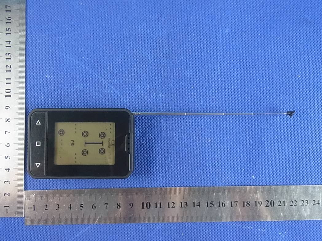
Click to zoom
Application Details
- Equipment Class
- CYY - Communications Receiver used w/Pt 15 Transmitter
- Date of Grant
- Aug 29, 2013
- Application Purpose
- Original Equipment
- Date of Application
- Aug 29, 2013
- Equipment Note
- TIRE PRESSURE MONITORING SYSTEM
- Frequency Range
- 434.20000000 - 434.20000000
- Country
- China
Documents & Files
Document Text
Text extracted from the exhibit documents filed with the FCC. Open a document above to read the original.
Users Manual
(For Car) SENSOR 2 TYRE GUARD 1 TYRE GUARD JET-M-300C (MONITOR) JET-M1-300C (MONITOR) JET-M2-300C (MONITOR) 1 Introduction 2 Function The monitor’s function is to receive the temperature and pressure information transmitted from a sensor fitted to each tyre and display this information on the screen in the specific units of measurement of your choice. The monitor will emit an alarm when a tyre pressure or temperature varies markedly from the targeted tyre pressure and/or temperature. The system will detect thigh or low air pressure as well as high temperature or rapid leakage from the tyres. The monitor will flash the red LED icon and an alarm will sound to remind the operator to check if the tyres are high or low in air pressure, leakage, high temperature or the monitor’s battery is low, or there is a problem with a sensor. This advanced tyre monitoring system offers these great features and benefits, is reliable, lightweight and compact. 3 Installation & Operating Instructions The following instructions show the identification of operating buttons of the monitor. Units Conversion Temperature Units Conversion F=9C/5+32 Note: C = Celsius; F = Fahrenheit Pressure Units Conversion 1 Bar=14.5 psi 1 Bar=100 kPa 2 1 Bar=1.02 kgf/cm installing the tyre sensors. vehicle’s tyres to your required pressures. Note: It is recommended to set tyre pressures at those recommended by the manufacturer listed in the vehicle’s handbook. “” button “ ” button SET button Congratulations on purchasing the new TYRE PRESSURE MONITORING (TPMS).This system is a safety system for monitoring vehicle’s tyre air pressure and temperature. It consists of external mounted tyre pressure wireless sensors fitted to the vehicle’s ryre valve and a hand-held monitor.The sensor will monitor the tyre’s air pressure and temperature.The sensor transmits the tyre pressure and temperature information to the dash-mounted/hand-held monitor. SYSTEM in standby mode,press" "button to change the pressure unit,white press" " button to change the temperature unit. NUMBERICAL INDICATING SECTION MONITOR icon PRESSURE CONDITION icon SENSOR icon TEMPERATURE icon PRESSURE UNIT icon Please ensure the monitor is fully charged and in the tyre alignment mode before Before installing sensors and setting the monitor,make sure you have inflated the The monitor can be placed on the dashboard,on the sun visor or mounted in any convenient place in the vehicle. 4 TYRE GUARD 3 TYRE GUARD Tyre alignment mode Hold down the “ ” and “” buttons simultaneously on the monitor for 5 seconds to enter tyre alignment mode, and press either “ ” or “” button to select the specific tyre that needs to be aligned. Screw a sensor to the tyre valve stem and the current pressure will be displayed against the corresponding flashing tyre icon on the screen. Once the tyre is aligned successfully the green light appears on the monitor. The red LED light appears on the monitor if the sensor hasn’t been aligned and “- - -” also appears on the monitor. Note: If the sensor is to be removed from one valve and fitted to another valve, you must delete the current setting on the monitor and realign this sensor to the new tyre. To delete an aligned sensor from a tyre, hold down the SET button for 5 seconds. When you exit the alignment mode, by again holding down the “ ” and “”, buttons simultaneously on the monitor for 5 seconds to check the pressures and temperatures, the monitor will indicate the data of the selected tyre. Click through to ensure all tyre pressures and temperature details are in accordance with your requirements. After your checks are completed, the backlight will go out and the monitor will indicate the tyre pressure of the selected tyre. Installation of the Sensor and anti-theft device It’s very simple to install the sensors. Screw a sensor to each tyre valve stem as the picture shows. Note: 1. Always install the sensor when the tyre is cold 2. Please check each tyre valve is not damaged. 3. Check to ensure there are no leaks and the sensors are firmly secured to each tyre valve. A Valve Anti-theft Devce Driver c The sensor has an anti theft ring to prevent the sensors being stolen. Firstly, place the anti_theft ring over the valve stem,with one side of the inner hexagon facing out, place the hexagon head of the sensor into the inner hexagon and then screw down the sensor; finally,place the inner hexagon screws of the anti-theft device and tighten with the key provided. Please refer to the right graphics A,B and C when installing the rings. Standard Pressure Setting Hold down SET button for 5 seconds to exit the Standard Pressure Setting mode. Hold down the set button of the monitor for 5 seconds to enter into the setting mode, as the right graphic shows. press“ ”or “ ”button to set the required pressure,and then quickly press the SET button to scroll through to the next the tyre and repeat this sequence to set the remaining tyres. Examination of the Tyre Condition The monitor indicates " --- " when a specific sensor's alignment is lost from the monitor, as graphic A shows. refer to Tyre Alignment Mode on page 3 to realign sensor. The monitor will indicate the " noS " signal whenever a sensor is either out of range or may be faulty,as graphic B shows. Installation of the Monitor The monitor can be mounted using the pedestal or brackets supplied. The monitor can be fixed to a suitable surface in the vehicle, sun visor, dashboard etc. It has a build-in lithium battery or you may wish to use a power source from within the vehicle’s power socket to charge or operate the monitor. TYRE GUARD 5 TYRE GUARD 6 Battery Capacity Indicator of the Monitor and Sensor When the monitor is low on power, the battery icon and “MONITOR” icon on the screen flash, the buzzer gives a 10 second intermittent alarm. The monitor then sounds every 30 seconds within 5 minutes of total discharge. Note: Please keep the monitor in a cool environment when charging. A B monitor Sensor battery replacemen…
Text truncated - open the document above for the full version.
Cover Letter(s)
Shenzhen Jetson Electronic Technologies Co.,Ltd SCS-F18: Project and Product Certification Representative Authorization Letter Page 1 of 2 Rev 3.0 775 Montague Expressway Milpitas, CA 95035 Tel: 408-526-1188 Fax: 408-526-1088 Email: [email protected] Project and Product Certification Representative Authorization Letter Revision History Reason for Amendment (current / obsolete) From To Approved Date Initial Release (obsolete) 1.0 1.0 Nov-14-2006 Revised wording (obsolete) 1.0 2.0 Sept–25-2007 Updated company template (current) 2.0 3.0 Jan-31-2012 Shenzhen Jetson Electronic Technologies Co.,Ltd SCS-F18: Project and Product Certification Representative Authorization Letter Page 2 of 2 Rev 3.0 2013/8/22 To: SIEMIC, INC. 775 Montague Expressway, Milpitas, CA 95035 USA Dear Sir/Madam, Re: Project and Product Certification Representative Authorization Letter We, Shenzhen Jetson Electronic Technologies Co.,Ltd hereby authorize SIEMIC, INC. to act as a Certification Body for certifying for the following project(s): Product: TIRE PRESSURE MONITORING SYSTEM Trade Name: JETSON Model Name: JET-M2-400C Serial Model: TMG400C,TM66,TM55-BRASS,TM55- ALUM,TT400C,TP7001,TP7002,JET- M2-300C,JET-M-400A,JET-M-400C,JET- 1000,JET-M1-700C,JET-M2-500,JET-M- 500 FCC ID : 2AAU3JET-M2-400C We affirm that between SIEMIC and Shenzhen Jetson Electronic Technologies Co.,Ltd , any difference in understanding, including test plan, measurement methods, applicable standards and relevant procedures and processes have been resolved prior to commencement of testing activities. Sincerely, Signature Name: May Lee Title: Manager Address: Rm1108 East Block 4,Seg sci-tech park,North Huaqiang Road,shenzhen 518031 China
Cover Letter(s)
SCS-F19: Confidentiality Request Letter Page 1 of 2 Rev 3.0 775 Montague Expressway Milpitas, CA 95035 Tel: 408-526-1188 Fax: 408-526-1088 Email: [email protected] Confidentiality Request Letter Revision History Reason for Amendment (current / obsolete) From To Approved Date Initial Release (obsolete) 1.0 1.0 Nov-14-2006 Adding CFR 2.459 (obsolete) 1.0 2.0 August – 11 - 2008 Updated company template & Added text box (current) 2.0 3.0 Jan-31-2012 SCS-F19: Confidentiality Request Letter Page 2 of 2 Rev 3.0 Shenzhen Jetson Electronic Technologies Co.,Ltd 2013-8-22 To: Federal Communications Commission Authorization and Evaluation Division 7435 Oakland Mills Road Columbia, MD Subject: Permanent Confidentiality Request for FCC ID: 2AAU3JET-M2-400C We hereby request confidential treatment of information accompanying this application as outlined below: - Block Diagram - Schematics - Operational Description The above materials contain trade secrets and proprietary information not customarily released to the public. The public disclosure of these materials may be harmful to the applicant and provide unjustified benefits to its competitors. The applicant understands that pursuant to Section 0.457 & 0.459 of the Rules, disclosure of this application and all accompanying documentation will not be made before the date of the Grant for this application. Sincerely, Client’s signature Signature Name: May Lee Title: Manager Address: Rm1108 East Block 4,Seg sci-tech park,North Huaqiang Road,shenzhen 518031 China
Cover Letter(s)
Shenzhen Jetson Electronic Technologies Co.,Ltd Model Difference FCC ID: 2AAU3JET-M2-400C Model : JET-M2-400C,TMG400C,TM66,TM55-BRASS,TM55-ALUM,TT400C, TP7001,TP7002,JET-M2-300C,JET-M-400A,JET-M-400C,JET-1000, JET-M1-700C,JET-M2-500,JET-M-500 Regards, Client’s signature Signature Name: May Lee Title: Manager Address: Rm1108 East Block 4,Seg sci-tech park,North Huaqiang Road, shenzhen 518031 China All the models are the same circuit and RF module, except the model names.
External Photos
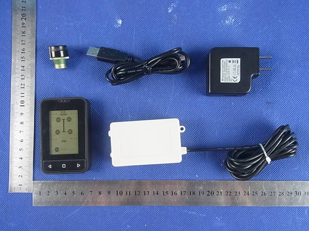
APPENDIX-PHOTOGRAPHS OF EUT CONSTRUCTIONAL DETAILS Photo 1 Photo 2 Photo 3 Photo 4 Photo 5 Photo 6 Photo 7
ID Label/Location Info
FCC ID LABELING AND LOCATION FCC ID Label TIRE PRESSURE MONITORING SYSTEM Model NO.:JET-M2-400C JETSON Input Rating:DC 5V/ 1000mA (Charging by Adapter) Battery:3.7V/ 1400mAh FCC ID: 2AAU3JET-M2-400C Shenzhen Jetson Electronic Technologies Co.,Ltd Made in China This device complies with part 15 of the FCC Rules. Operation is subject to the following two conditions: (1)This device may not cause harmful interference, and (2) this device must accept any interference received, including interference that may cause undesired operation. FCC ID Label Location The label shown shall be permanently affixed at a conspicuous location on the device and be readily visible to the user at the time purchase (Labeling requirements per 2.925)
Internal Photos
APPENDIX-PHOTOGRAPHS OF EUT CONSTRUCTIONAL DETAILS Photo 1 Photo 2 ANT Photo 3 Photo 12 Photo 13 Photo 14
Test Report
Page 1 of 21 Report No.: NTEK-2013NT0730852E FCC TEST REPORT FCC ID: 2AAU3JET-M2-400C Product: TIRE PRESSURE MONITORING SYSTEM Trade Name: JETSON Model Number: JET-M2-400C Serial Model: TMG400C,TM66,TM55-BRASS,TM55-ALUM, TT400C,TP7001,TP7002,JET-M2-300C, JET-M-400A,JET-M-400C,JET-1000, JET-M1-700C,JET-M2-500,JET-M-500 Report No.: NTEK-2013NT0730852F Prepared for Shenzhen Jetson Electronic Technologies Co.,Ltd Rm1108 East Block 4,Seg sci-tech park,North Huaqiang Road,shenzhen 518031 China Prepared by Shenzhen NTEK Testing Technology Co., Ltd. 1/F, Building E, Fenda Science Park, Sanwei Community, Xixiang Street, Bao’an District, Shenzhen P.R. China Tel.: +86-0755-61156588 Fax.: +86-0755-61156599 Website: www.ntek.org.cn Page 2 of 21 Report No.: NTEK-2013NT0730852E TEST RESULT CERTIFICATION Applicant’s name................. : Shenzhen Jetson Electronic Technologies Co.,Ltd Address ................................. : Rm1108 East Block 4,Seg sci-tech park,North Huaqiang Road, shenzhen 518031 China Manufacturer's Name.......... : Shenzhen Jetson Electronic Co.,Ltd Address ................................. : 6/F,Block A,Jjingdingsheng Industirial Park Qinghua Road, Bao’an District ,Shenzhen 51809 China Product description Product name ........................... : TIRE PRESSURE MONITORING SYSTEM Model and/or type reference : TMG400C Serial Model: TM66,TM55-BRASS,TM55-ALUM,TT400C,TP7001,TP7002, JET-M2-300C,JET-M-400A,JET-M-400C,JET-1000, JET-M1-700C,JET-M2-500,JET-M-500 Standards............................. : FCC Part15B:2012 ANSI C63.4:2009 This device described above has been tested by NTEK, and the test results show that the equipment under test (EUT) is in compliance with Part 15 of FCC Rules. And it is applicable only to the tested sample identified in the report. This report shall not be reproduced except in full, without the written approval of NTEK, this document may be altered or revised by NTEK, personal only, and shall be noted in the revision of the document. Date of Test............................................: Date (s) of performance of tests .............: 30 Jul. 2013 ~14 Aug. 2013 Date of Issue...........................................: 14 Aug. 2013 Test Result...............................................: Pass Testing Engineer : (Polo Cha) Technical Manager : (Brown Lu) Authorized Signatory : (Bovey Yang) Page 3 of 21 Report No.: NTEK-2013NT0730852E Table of Contents Page 1 . TEST SUMMARY 4 1.1 TEST FACILITY 5 1.2 MEASUREMENT UNCERTAINTY 5 2 . GENERAL INFORMATION 6 2.1 GENERAL DESCRIPTION OF EUT 6 2.2 DESCRIPTION OF TEST MODES 7 2.3 DESCRIPTION OF TEST SETUP 8 2.4 DESCRIPTION TEST PERIPHERAL AND EUT PERIPHERAL 9 2.5 MEASUREMENT INSTRUMENTS LIST 10 3 . EMC EMISSION TEST 11 3.1 CONDUCTED EMISSION MEASUREMENT 11 3.1.1 POWER LINE CONDUCTED EMISSION 11 3.1.2 TEST PROCEDURE 12 3.1.3 TEST SETUP 12 3.1.4 EUT OPERATING CONDITIONS 12 3.1.5 TEST RESULTS 13 3.2 RADIATED EMISSION MEASUREMENT 15 3.2.1 LIMITS OF RADIATED EMISSION MEASUREMENT 15 3.2.2 TEST PROCEDURE 15 3.2.3 TEST SETUP 16 3.2.4 EUT OPERATING CONDITIONS 16 3.2.5 TEST RESULTS 17 3.2.6 TEST RESULTS(Above 1GHz) 19 4 . EUT TEST PHOTO 20 Page 4 of 21 Report No.: NTEK-2013NT0730852E 1. TEST SUMMARY Test procedures according to the technical standards: EMC Emission Standard Test Item Limit Judgment Remark Conducted Emission Class B PASS FCC Part15B:2012 ANSI C63.4: 2009 Radiated Emission Class B PASS NOTE: (1) ’N/A’ denotes test is not applicable in this Test Report (2) For client’s request and manual description, the test will not be executed. Page 5 of 21 Report No.: NTEK-2013NT0730852E 1.1 TEST FACILITY NTEK Testing Technology Co., Ltd Add. : 1/F, Building E, Fenda Science Park, Sanwei Community, Xixiang Street, Bao’an District, Shenzhen P.R. China. FCC Registration Number:238937; IC Registration Number:9270A-1 CNAS Registration Number:L5516 1.2 MEASUREMENT UNCERTAINTY The reported uncertainty of measurement y ± U,where expended uncertainty U is based on a standard uncertainty multiplied by a coverage factor of k=2,providing a level of confidence of approximately 95 %. A. Conducted Measurement : Test Site Method Measurement Frequency Range U,(dB) NOTE NTEKC01 ANSI150 KHz ~ 30MHz 3.2 B. Radiated Measurement : Test Site Method Measurement Frequency Range U,(dB) NOTE NTEKA01 ANSI30MHz ~ 1000MHz 4.7 1GHz ~6GHz 5.0 Page 6 of 21 Report No.: NTEK-2013NT0730852E 2. GENERAL INFORMATION 2.1 GENERAL DESCRIPTION OF EUT Equipment TIRE PRESSURE MONITORING SYSTEM Model Name JET-M2-400C Additional Model Number(s) TM66,TM55-BRASS,TM55-ALUM,TT400C,TP7001, TP7002,JET-M2-300C,JET-M-400A,JET-M-400C, JET-1000,JET-M1-700C,JET-M2-500,JET-M-500 Model Difference All models are identical except model names. Product Description The EUT is a TIRE PRESSURE MONITORING SYSTEM. Based on the application, features, or specification exhibited in User's Manual, the EUT is considered as an ITE/Computing Device. More details of EUT technical specification, please refer to the User's Manual. Operating frequency: 434.2MHz(receive) Connecting I/O port: N/A Adapter Model No.: BI05-050100-BdC AC Power Input: 100-240V~, 50/60Hz, 0.3A Output: 5V , 1A Battery DC 3.7V, 1400mAh Page 7 of 21 Report No.: NTEK-2013NT0730852E 2.2 DESCRIPTION OF TEST MODES To investigate the maximum EMI emission characteristics generates from EUT, the test system was pre-scanning tested base on the consideration of following EUT operation mode or test configuration mode which possible have effect on EMI emission level. Each of these EUT operation mode(s) or test configuration mode(s) mentioned above was evaluated respectively. Pretest Mode Description Mode 1 Running For Conducted Test Final Test Mode Description Mode 1 Running For Radiated Test Final Test Mode Description Mode 1 Running Page 8 of 21 Report No.: NTEK-2013NT0730852E 2.3 DESCRIPTION OF TEST SETUP Mode CE: 0.8m 0.1m 1.5m C-1 AC Line E-2 Adapter Table E-1 EUT LISN Page 9 of 21 Report No.: NTEK-2013NT0730852E 2.4 DESCRIPTION TEST P…
Text truncated - open the document above for the full version.
Test Setup Photos
Page 20 of 21 Report No.: NTEK-2013NT0730852E 4. EUT TEST PHOTO Radiated Measurement Photos Page 21 of 21 Report No.: NTEK-2013NT0730852E Conducted Measurement Photos
Contact Information
Applicant
Sam zheng(General manager)
Test Firm
Shenzhen NTEK Testing Technology Co., Ltd.Jason Chen
Technical Specifications
| # | Rule Parts | Frequency Range | Power Output |
|---|---|---|---|
| 1 | 15B | 434.2 MHz - 434.2 MHz | - |
Other Applications from Shenzhen Jetson Electronic Technologies Co.,Ltd
2AAU3JET-100A
Aug 28, 2013WIRED BOOSTER
Equipment Class
DSC - Part 15 Security/Remote Control Transmitter