2AAVI-M1MINIHF RFID Reader Module with a built-in antenna
JADAK, a business unit of Novanta Corporation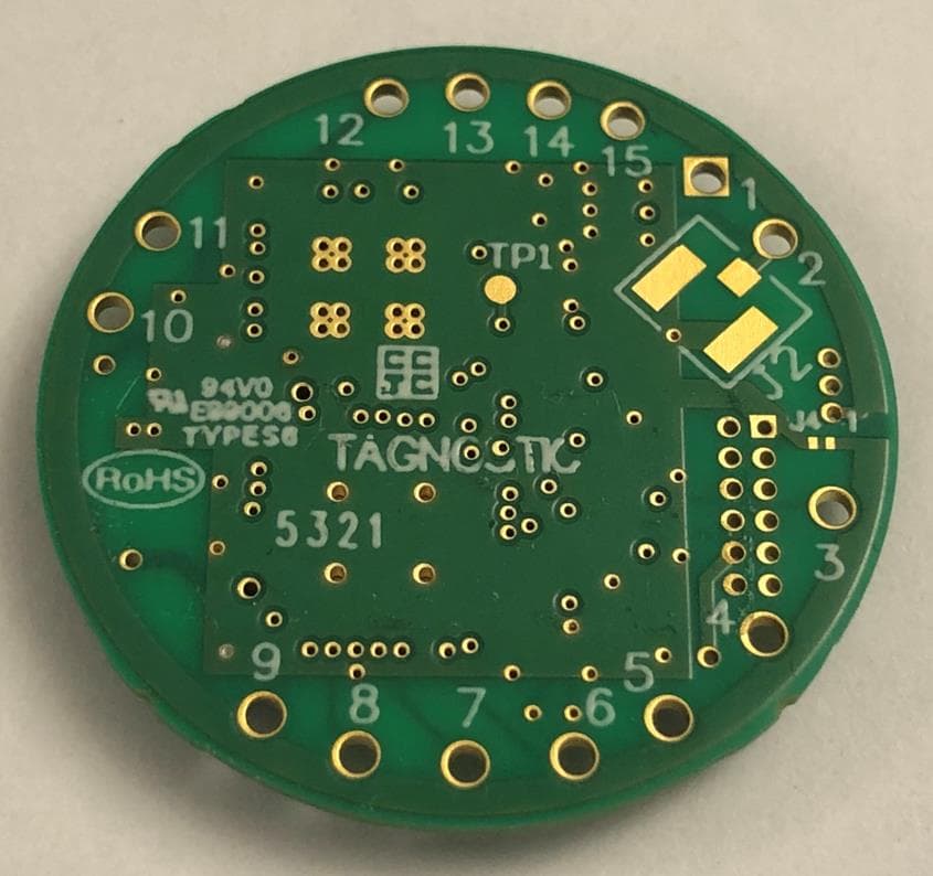
Click to zoom
Application Details
- Equipment Class
- DXX - Part 15 Low Power Communication Device Transmitter
- Date of Grant
- Jun 02, 2022
- Application Purpose
- Original Equipment
- Date of Application
- May 30, 2022
- Equipment Note
- HF RFID Reader Module with a built-in antenna
- Frequency Range
- 13.56000000 - 13.56000000
- Country
- United States
Documents & Files
Document Text
Text extracted from the exhibit documents filed with the FCC. Open a document above to read the original.
Users Manual
M1-Mini User Guide M1-MINI USER GUIDE REV. 05/27/2022 M1-Mini User Guide COPYRIGHT INFORMATION: Copyright 2022 Novanta Corporation. All rights reserved. Version 05/17/2022 This product or document is protected by copyright and distributed under licenses restricting its use, copying, distribution, and decompilation. No part of this product or document may be reproduced in any form by any means without prior written authorization of Novanta Corporation and its licensors, if any. CryptoRF is a registered trademark of Atmel Corporation. MIFARE and NXP is a registered trademark of Royal Philips Electronics. Tag-it is a trademark of Texas Instruments, Incorporated. Microsoft and Windows are registered trademarks of Microsoft Corporation. TECHNICAL SUPPORT AND CONTACT INFORMATION: TELEPHONE: 315.701.0678 www.jadaktech.com Email: [email protected] 3 TABLE OF CONTENTS 1 About this Document ................................................................................................................................................... 8 1.1 Intended Audience ............................................................................................................................................. 8 1.2 Topics Covered ................................................................................................................................................... 8 1.3 Topics Not Covered ............................................................................................................................................ 8 1.4 Additional Documentation ................................................................................................................................. 9 1.5 Revision History ................................................................................................................................................. 9 2 Definition of Terms .................................................................................................................................................... 10 3 Ordering Information ................................................................................................................................................ 11 3.1 Part Numbers ................................................................................................................................................... 11 4 SkyeModule M1-Mini Overview ................................................................................................................................ 12 4.1 Features ........................................................................................................................................................... 13 5 Mechanical Specifications ......................................................................................................................................... 14 5.1 Dimensioned Drawings .................................................................................................................................... 14 6 Pinning Information ................................................................................................................................................... 15 6.1 Pin Locations .................................................................................................................................................... 15 7 Environmental Specifications .................................................................................................................................... 16 7.1 Electrostatic Precautions .................................................................................................................................. 16 7.2 Temperature Ratings ........................................................................................................................................ 16 8 Electrical Specifications ............................................................................................................................................. 17 8.1 Absolute Maximum Ratings ............................................................................................................................. 18 8.2 Power Supply Options ...................................................................................................................................... 19 9 Host Interface Specifications ..................................................................................................................................... 20 9.1 TTL Serial .......................................................................................................................................................... 20 9.2 SPI ..................................................................................................................................................................... 21 I 2 C ..................................................................................................................................................................... 22 9.3 4 10 Radio Specifications and Regional Compliance ..................................................................................................... 23 10.1 Agency Approval ............................................................................................................................................... 23 10.2Modular Certifications ...................................................................................................................................... 23 10.3 Frequency Band ................................................................................................................................................ 23 10.4 Tag Protocols..................................................................................................................................................... 23 11 Antenna Options ...............................................................…
Text truncated - open the document above for the full version.
Cover Letter(s)
SCS-F018: Project and Product Certification Representative Authorization Letter Page 1 of 2 Rev 7.0 75 Montague Expressway Milpitas, CA 95035 Tel: 408-526-1188 Fax: 408-526-1088 Email: [email protected] Website: https://www.cps.bureauveritas.com/ Project and Product Certification Representative Authorization Letter Reason for Amendment (current / obsolete) Revision History Approved Date From To Initial Release (obsolete) 1.0 1.0 Nov-14-2006 Revised wording (obsolete) 1.0 2.0 Sept–25-2007 Updated company template (obsolete) 2.0 3.0 Jan-31-2012 Updated letter information (obsolete) 3.0 4.0 May-23-2014 Added FCC ID field (obsolete) 4.0 5.0 Sep-16-2014 Updated company name & logo (current) 5.0 6.0 Jun-27-2018 Updated References and Contact info 6.0 7.0 Aug-30-202 SCS-F018: Project and Product Certification Representative Authorization Letter Page 2 of 2 Rev 7.0 3/1/2022 To: BVCPS, INC. 775 Montague Expressway, Milpitas, CA 95035 USA Dear Sir/Madam, Re: Project and Product Certification Representative Authorization Letter We, JADAK, a business unit of Novanta Corporation, hereby authorize Bureau Veritas Consumer Product Services, Inc. to act as a Certification Body for certifying for the following project(s): FCC ID: 2AAVI-M1MINI Product Description: HF RFID EMBEDDED READER MODULE Model: M1-Mini We affirm that between Bureau Veritas Consumer Product Services, Inc. and JADAK, a business unit of Novanta Corporation, any difference in understanding, including test plan, measurement methods, applicable standards and relevant procedures and processes have been resolved prior to commencement of testing activities. Sincerely, EVA GRAVIUS Vice President, Operations - JADAK • Production Management 7279 William Barry Blvd, North Syracuse, NY 13212 USA T +1 315 218 1343 Email: [email protected]
Cover Letter(s)
SCS-F026 Modular Approval Letter Page 1 of 2 Rev 13.0 775 Montague Expressway Milpitas, CA 95035 Tel: 408-526-1188 Fax: 408-526-1088 Email: [email protected] Website: https://www.cps.bureauveritas.com/ Modular Approval Declaration Letter Reason for Amendment (current / obsolete) Revision History Approved Date From To Initial Release (Obsolete) 1.0 1.0 Dec-04-2006 Added IC Modular Letter (Obsolete) 1.0 2.0 Feb 16 2009 Add LMA and MA option (Obsolete) 2.0 3.0 April 14 2010 Revised per RSS Gen issue 3.0 (Obsolete) 3.0 4.0 Jan 12 2011 Removed Foot(2) (obsolete) 4.0 5.0 July 19 2011 Adding New note per KDB996369 D01 V01R03 (obsolete) 5.0 6.0 August 29 2011 Updated company template & Added text box (obsolete) 6.0 7.0 Jan-31-2012 Updated modular requirement (obsolete) 7.0 8.0 Sept 05 2014 Updated template to meet RSP 100 issue 10 (obsolete) 8.0 9.0 Nov 20 2014 Updated template to meet RSP 100 issue 11 (obsolete)) 9.0 10.0 March 19 2015 Revised the Modular Requirement statements (obsolete) 10.0 11.0 July 28, 2016 Updated template with BV logo (current) 11.0 12.0 June 26, 2019 Updated contact info and references 12.0 13.0 Aug-30-2020 SCS-F026 Modular Approval Letter Page 2 of 2 Rev 13.0 03/1/22 (Product name) FCC ID: 2AAVI-M1MINI , is seeking FCC Authorization as a Single Modular Transmitter / Single Limited Modular Transmitter (Please check one) The EUT meets the requirements for Single Modular Approval / Single Limited Modular Approval (Please check one) as detailed in KDB 996369. Compliance to each of the requirements is described below: Item Modular requirement Yes No Please provide a detailed explanation if the answer is “No.” 1 Have its own RF shielding x 2 Have buffered modulation/data inputs (if such inputs are provided) x 3 The modular transmitter must have its own power supply regulation. x 4 Meet the antenna requirements of section 15.203 x 5 Be tested in a stand-alone configuration, i.e., the antenna, AC or DC power and data input/output lines must be connected to the module but, the module must not be inside another case during testing. x 6 Be labeled with its own FCC ID number, and if the FCC ID is not visible when the module is installed inside another device, then the outside of the device into which the module is installed must also display a label referring to the enclosed module. x 7 The modular transmitter is manufactured so that the user can not influence the operation of the transmitter that will operate outside of the scope of the regulations. x 8 Address compliance with the Commission`s RF exposure limits in Sections 1.1310 and 2.1093. x Note: (1) LMA may be granted when one or more of the requirements in the table above cannot be demonstrated. LMA will also be issued in those instances where applicants can demonstrate that they will retain control over the final installation of the device, such that compliance of the end product is assured. In such cases, an operating condition on the LMA for the module must state that the module is only approved for use when installed in devices produced by a specific manufacturer. When LMA is sought, the application for equipment certification must specifically state how control of the end product into which the module will be installed, and will be maintained, such that full compliance of the end product is always ensured. (2) Please provide Clear and specific instructions describing the conditions, limitations and procedures for third-parties to use and/or integrate the module into a host device. (3) For non-Software Defined Radio transmitter modules where software is used to ensure compliance of the device, technical description of how such control is implemented to ensure prevention of third party modification must be provided (see KDB 594280). Note 1: Compliance of a module in its final configuration is the responsibility of the applicant. A host device will not be considered certified if the instructions regarding antenna configuration provided in the original description, of one or more separately certified modules it contains, were not followed. Example: A separately certified low-power transceiver module using Bluetooth technology which is housed in a desktop computer, laptop or peripheral does not require the overall system to be recertified, if the desktop computer, laptop or peripheral, as a stand-alone unit, complies with all applicable technical standards. EVA GRAVIUS Vice President, Operations - JADAK • Production Management 7279 William Barry Blvd, North Syracuse, NY 13212 USA T +1 315 218 1343 Email: [email protected]
External Photos
ExternalImages of M1-Mini FCCID: 2AAVI-M1MINI IC: 11355A-M1MINI Top Viewof M1-Mini with Shield Side view 1 of M1-Mini with Shield Side view 2 of M1-Mini with Shield Side view 3 of M1-Mini with Shield Side view 4 of M1-Mini with Shield Bottomview of M1-Mini
Internal Photos
Internal Images of M1-Mini FCCID:2AAVI-M1MINI IC:11355A-M1MINI Top Side of M1-Mini with Shield Top Side of M1-Mini without shield Bottom Side of M1-Mini
RF Exposure Info
Bureau Veritas Consumer Product Services, Inc. FCC ID: 2AAVI-M1MINI One Distribution Center Circle, Ste #1, Littleton, MA 01460, USA Report No: FCC_DAN011322-2_MPE Page 1 of 6 RF Exposure Report (Portable Conditions) Prepared for Novanta This report presents Maximum Permissible Exposure for M1-MINI Prepared by Randle Sherian Engineer Issue date: May 25, 2022 Bureau Veritas Consumer Product Services, Inc. FCC ID: 2AAVI-M1MINI One Distribution Center Circle, Ste #1, Littleton, MA 01460, USA Report No: FCC_DAN011322-2_MPE Page 2 of 6 This test result relates only to the described test object. This document shall not be reproduced, except in full, without the written approval of Bureau Veritas Test Lab. Customer must not use this test report as the product certification of each accreditation body or each national organization. The test is traceable to national standard or related international standard Contents • Test Request Information ............................................................................................................................. 3 • Test Laboratory Information ......................................................................................................................... 3 • RF Exposure ................................................................................................................................................. 4 Bureau Veritas Consumer Product Services, Inc. FCC ID: 2AAVI-M1MINI One Distribution Center Circle, Ste #1, Littleton, MA 01460, USA Report No: FCC_DAN011322-2_MPE Page 3 of 6 • Test Request Information Test Requested By: Novanta 125 Middlesex Turnpike, Bedford, MA 01730 Bedford, MA 01730 Category of DUT: Portable Exposure; General Population / Uncontrolled Exposure Type of Test: RF Exposure Exemption Calculation References: KDB 447498 v06 FCC CFR Title 47, Chapter I, Subchapter A, Subpart I, Part 2.1091 Deviations from standard: None Date of Assessment: 05/25/2022 • Test Laboratory Information Location of Test Lab: Bureau Veritas Consumer Product Services, Inc. One Distribution Center Circle, Ste #1, Littleton, MA 01460, USA Key Contact: Ozgur Ozturk (General Manager) Ozgur [email protected] Laboratory Accreditations: BUREAU VERITAS CONSUMER PRODUCTS SERVICES, INC is accredited in accordance with the recognized International Standard ISO/IEC 17025:2017 General requirements for the competence of testing and calibration laboratories. ISO/IEC 17025:2017: 1627-01 FCC Test Site Number: US1028 IC Test Site Number: US0106 Bureau Veritas Consumer Product Services, Inc. FCC ID: 2AAVI-M1MINI One Distribution Center Circle, Ste #1, Littleton, MA 01460, USA Report No: FCC_DAN011322-2_MPE Page 4 of 6 1. RF Exposure 1.1 Limits for Maximum Permissible Exposure (MPE) Following FCC KDB 447498 D01 “General SAR test exclusion guidance” a) For 100 MHz to 6 GHz and test separation distances ≤ 50 mm, the 1-g and 10-g SAR test exclusion thresholds are determined by the following: [(max. power of channel, including tune-up tolerance, mW) / (min. test separation distance, mm)] · [√f(GHz)] ≤ 3.0 for 1-g SAR, and ≤ 7.5 for 10-g extremity SAR,where • f(GHz) is the RF channel transmit frequency in GHz • Power and distance are rounded to the nearest mW and mm before calculation • The result is rounded to one decimal place for comparison • The values 3.0 and 7.5 are referred to as numeric thresholds in step b) below The test exclusions are applicable only when the minimum test separation distance is ≤ 50 mm, and for transmission frequencies between 100 MHz and 6 GHz. When the minimum test separation distance is < 5 mm, a distance of 5 mm according to 4.1 f) is applied to determine SAR test exclusion. b) For 100 MHz to 6 GHz and test separation distances > 50 mm, the 1-g and 10-g SAR test exclusion thresholds are determined by the following (also illustrated in Appendix B): 1) {[Power allowed at numeric threshold for 50 mm in step a)] + [(test separation distance – 50 mm)·(f(MHz)/150)]} mW, for 100 MHz to 1500 MHz 2) {[Power allowed at numeric threshold for 50 mm in step a)] + [(test separation distance – 50 mm)·10]} mW, for > 1500 MHz and ≤ 6 GHz c) For frequencies below 100 MHz, the following may be considered for SAR test exclusion (also illustrated in Appendix C): 1) For test separation distances > 50 mm and < 200 mm, the power threshold at the Corresponding test separation distance at 100 MHz in step b) is multiplied by [1 + log(100/f(MHz))] 2) For test separation distances ≤ 50 mm, the power threshold determined by the equation in 1) for 50 mm and 100 MHz is multiplied by ½ 1.2 MPE Calculation Formula 푺푺= 푷푷 풐풐풐풐풐풐 푮푮 ퟒퟒퟒퟒ푹푹 ퟐퟐ Where: S = power density in mW/cm 2 P out = output power to antenna in mW Bureau Veritas Consumer Product Services, Inc. FCC ID: 2AAVI-M1MINI One Distribution Center Circle, Ste #1, Littleton, MA 01460, USA Report No: FCC_DAN011322-2_MPE Page 5 of 6 G = gain of antenna in linear scale R = distance between observation point and centre of the radiator in cm 1.3 Classification The antenna of this product, under normal use condition, is at 0mm seperation away from the body of the user. Therefore this device is classified as Portable Device. 1.4 Antenna information Antenna Type 4 Loop Coil Antenna on PCB 1.5 Determining EIRP The following calculation was used to convert field strength measurement at 3 meters to dBm EIRP. EIRP(dBm) = E(dBμV/m) − 95.3 Highest Measured Field Strength = 61.9 dBuV/m = -33.4 dBm EIRP = 0.00046 mWatts EIRP 1.6 Calculation Result of Single RF Source(s) Following FCC KDB 447498 D01 “General SAR test exclusion guidance a) For 100 MHz to 6 GHz and test separation distances ≤ 50 mm, the 1-g and 10-g SAR test exclusion thresholds are determined by the following: [(max. power of channel, including tune-up tolerance, mW) / (min. test separation distance, mm)] · [√f(GHz)] ≤ 3.0 for 1-g SAR, and ≤ 7.5 for 10-g extremity SAR, where • f(GHz) is the RF channel transmit frequency in GHz • Power and distance a…
Text truncated - open the document above for the full version.
Test Report
Bureau Veritas is accredited by the American Association for Laboratory Accreditation for the specific scope of accreditation under Certificate Number 1627-01. This report may contain data which is not covered by the A2LA accreditation. ____________________________________________________________ One Distribution Center Circle, #1 • Littleton, MA • TEL (978) 486-8880 • FAX (978) 486-8828 page 1 of 23 Test Report Report No DAN011322-2 Client Novanta Contact Daniel Ratner Address 125 Middlesex Turnpike Bedford, MA 01730 Phone N/a Items tested 13.56 MHz RFID Module FCC ID 2AAVI-M1MINI IC 11355A-M1MINI PMN M1-Mini Model/HVIN M1-Mini Equipment Code Part Number RFID ASSY-00038 FCC/IC Rule Parts CFR Title 47 FCC Part 15.225, ISED Canada RSS-210 Issue 10 Annex B.6 Test Dates 2/8/2022 to 2/14/2022 Results As detailed within this report Prepared by Randle Sherian– EMC Engineer Authorized by Ryan M. Brown – Sr. Engineer Issue Date 5/1/2022 FCC Site Number US1028 ISED CAB Conditions of Issue US0106 This Test Report is issued subject to the conditions stated in the ‘Conditions of Testing’ section on page 32 of this report. Test Report for Novanta• Report No. DAN011322-2 May 1, 2022 ______________________________________________________________________ ____________________________________________________________ Curtis-Straus LLC, a wholly owned subsidiary of BV CPS One Distribution Center Circle, #1 • Littleton, MA • TEL (978) 486-8880 • FAX (978) 486-8828 page 2 of 23 Contents Contents .................................................................................................................................... 2 Summary and Test Methodology .............................................................................................. 3 Product Tested - Configuration Documentation ........................................................................ 6 Summary of Results .................................................................................................................. 7 Modifications Required for Compliance ..................................................................................... 7 Test Results .............................................................................................................................. 8 Fundamental and Emissions Mask ........................................................................................ 8 99% Occupied Bandwidth ...................................................................................................... 9 Radiated Spurious Emissions .............................................................................................. 10 Temperature Stability ........................................................................................................... 13 AC Line Conducted Emissions ............................................................................................ 14 Measurement Uncertainty ....................................................................................................... 21 Conditions of Testing ............................................................................................................... 22 Form Final Report REV 12-07-15 Test Report for Novanta• Report No. DAN011322-2 May 1, 2022 ______________________________________________________________________ _____________________________________________________________ One Distribution Center Circle, #1 • Littleton, MA • TEL (978) 486-8880 • FAX (978) 486-8828 page 3 of 23 Summary and Test Methodology This test report supports an application for certification of a transmitter operating pursuant to: CFR Title 47 FCC Part 15.225, ISED Canada RSS-210 Issue 10 Annex B.6 The M1-Mini is a multi-protocol RFID read/write module for use with most industry standard 13.56 megahertz (MHz) RFID tags and smart labels. All testing was performed in accordance with ANSI C63.10 2013. The EUT was evaluated in the x, y, and z plane with the loop antenna in Parallel, Perpendicular, and parallel to the ground positions to determine worst case for radiated emission. The worst case plane was y-plane and with the loop antenna in perpendicular position. The worst case results were recorded. We found that the product met the above requirements with no modifications. Test sample was received in good condition. The environmental conditions during testing are documented on the associated data tables. Following bandwidths were used during emissions testing. Frequency RBW VBW 9kHz-150kHz 200Hz 1kHz 150kHz-30MHz 9kHz 30kHz 30MHz-1GHz 120kHz 1MHz The limits in CFR 47, Part 15, Subpart C, paragraph 15.209 (a), are identical to those in RSS- GEN Section 8.9, Table 6, since the measurements are performed in terms of magnetic field strength and converted to electric field strength levels (as reported in the table) using the free space impedance of 377Ω. Spurious Emissions was performed in a Semi-Aniconic Chamber EUT was rotated 360 degrees. For measurements at and above above 30MHz, the measurement antenna was raised and lowered from 1-4 Meters. Test Report for Novanta• Report No. DAN011322-2 May 1, 2022 ______________________________________________________________________ _____________________________________________________________ One Distribution Center Circle, #1 • Littleton, MA • TEL (978) 486-8880 • FAX (978) 486-8828 page 4 of 23 Below 30MHz test setup Below 1GHz test setup Ant. Tower 1-4m Turn Table EUT Ground Plane Spectrum 0.8m 3m Test Report for Novanta• Report No. DAN011322-2 May 1, 2022 ______________________________________________________________________ _____________________________________________________________ One Distribution Center Circle, #1 • Littleton, MA • TEL (978) 486-8880 • FAX (978) 486-8828 page 5 of 23 Above 1GHz test setup 3m 1-4m Variable Turn Table EUT& Support Units Ground Plane Test Receiver 150cm Absorbe r Ant. Tower Test Report for Novanta• Report No. DAN011322-2 May 1, 2022 ________________________________…
Text truncated - open the document above for the full version.
Test Setup Photos
Bureau Veritas Consumer Product Services, Inc. FCC ID: 2AAVI-M1MINI One Distribution Center Circle, Ste #1, Littleton, MA 01460, USA ISED IC: 11355A-M1MINI Test Setup Photos Bureau Veritas Consumer Product Services, Inc. FCC ID: 2AAVI-M1MINI One Distribution Center Circle, Ste #1, Littleton, MA 01460, USA ISED IC: 11355A-M1MINI AC Mains Conducted Emissions Front AC Mains Back Bureau Veritas Consumer Product Services, Inc. FCC ID: 2AAVI-M1MINI One Distribution Center Circle, Ste #1, Littleton, MA 01460, USA ISED IC: 11355A-M1MINI Y-Plane RSE Below 30MHz Front Y-Plane RSE Below 30MHz Back Bureau Veritas Consumer Product Services, Inc. FCC ID: 2AAVI-M1MINI One Distribution Center Circle, Ste #1, Littleton, MA 01460, USA ISED IC: 11355A-M1MINI Y-Plane RSE 30MHz – 1GHz Front Y-Plane RSE Below 30MHz – 1GHz Back Bureau Veritas Consumer Product Services, Inc. FCC ID: 2AAVI-M1MINI One Distribution Center Circle, Ste #1, Littleton, MA 01460, USA ISED IC: 11355A-M1MINI Temperature Chamber Setup
Contact Information
Applicant
Eva Gravius(VP Engineering)
Test Firm
BUREAU VERITAS CONSUMER PRODUCTS SERVICES, INC.Ozgur Ozturk
[email protected]978-486-8880
Technical Specifications
| # | Rule Parts | Frequency Range | Power Output |
|---|---|---|---|
| 1 | 15C | 13.56 MHz - 13.56 MHz | - |
Other Applications from JADAK, a business unit of Novanta Corporation
2AAVI-HS2R9
Dec 03, 2015RFID/Bluetooth Handheld Scanner
Equipment Class
DXX - Part 15 Low Power Communication Device Transmitter
2AAVI-HS1RN4
Sep 22, 2015RFID Module
Equipment Class
DXX - Part 15 Low Power Communication Device Transmitter2AAVI-JDK1901
Oct 27, 2013RFID Module
Equipment Class
DXX - Part 15 Low Power Communication Device Transmitter