FCCID.CO- FCC ID Database
HomeCompaniesEquipment ClassesSearch

© 2026 FCC ID Database. All rights reserved.

AboutContactData sourced from FCC public records
  1. Home/
  2. Druck Ltd/
  3. 2AAVWADTS552F-01

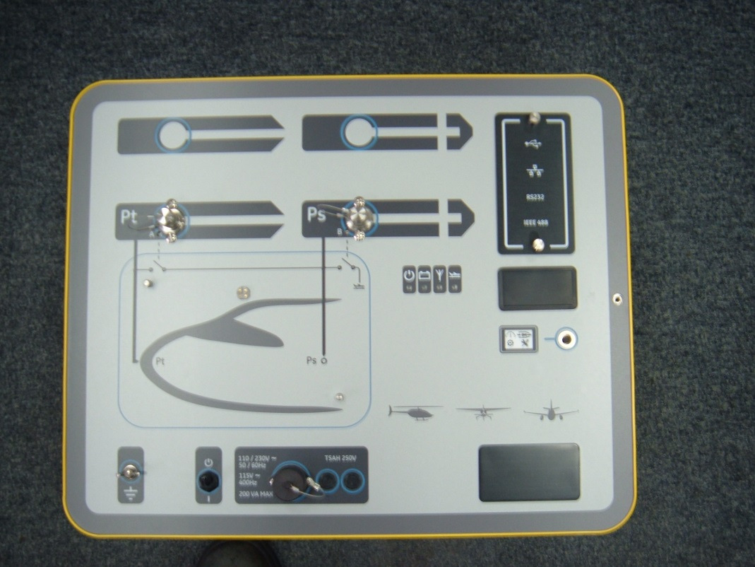
2AAVWADTS552F-01Air Data Test Set ADTS552F

Druck Ltd
Air Data Test Set ADTS552F - FCC ID 2AAVWADTS552F-01 - Druck Ltd
Click to zoom

Application Details

Equipment Class
DSS - Part 15 Spread Spectrum Transmitter
Date of Grant
Sep 29, 2015
Application Purpose
Original Equipment
Date of Application
Sep 29, 2015
Equipment Note
Air Data Test Set ADTS552F
Frequency Range
2402.00000000 - 2480.00000000
Company
Druck Ltd
Country
United Kingdom

Documents & Files

Select a file to view
Users Manual

↗

Attestation Statements

↗

Cover Letter(s)

↗
↗

External Photos

↗

ID Label/Location Info

↗
↗

Internal Photos

↗

RF Exposure Info

↗

Test Report

↗

Test Setup Photos

↗

Document Text

Text extracted from the exhibit documents filed with the FCC. Open a document above to read the original.

Users Manual

GE Measurement & Control GE Air Data Test Sets ADTS542F/552F/553F/554F User Manual K0553 © 2014 General Electric Company. All Rights Reserved. Specifications are subject to change without notice. GE is a registered trademark of General Electric Company. Other company or product names mentioned in this document may be trademarks or registered trademarks of their respective companies, which are not affiliated with GE. The Bluetooth® word mark and logos are registered trademarks owned by Bluetooth SIG, Inc. and any use of such marks by GE is under license. ADTS542F/552F/553F/554F User Manual 1 K0553 Revision A Introduction This Use Manual provides operating instructions for the Air Data Test Sets (ADTS) compatible with the requirements of first line operation. Scope This Use Manual contains the description, identification data and operating procedures for the user of this equipment . Safety The manufacturer has designed this equipment to be safe when operated using the procedures detailed in this manual and the Safety and Installation Guide K0554. Do not use this equipment for any other purpose than that stated. This publication contains operating and safety instructions that must be followed to ensure safe operation and to maintain the equipment in a safe condition. The safety instructions are either warnings or cautions issued to protect the user and the equipment from injury or damage. Use qualified* technicians and good engineering practice for all procedures in this publication. Pressure Do not apply pressure greater than the maximum safe working pressure to the equipment . Toxic Materials There are no known toxic materials used in this equipment . Maintenance The equipment must be maintained using the manufacturer’s procedures and should be carried out by the manufacturer’s service department or approved service agents. Technical Advice For technical advice contact the manufacturer or subsidiary. *A qualified technician must have the necessary technical knowledge, documentation, special test equipment and tools to carry out the required work on this equipment . 2 ADTS542F/552F/553F/554F User Manual K0553 Revision A Marks and Symbols on the equipment This equipment meets the requirements of all relevant European safety directives. The equipment carries the CE mark. This symbol, on the equipment , indicates that the user should read the user manual. This symbol, on the equipment , indicates a warning and that the user should refer to the user manual. Do not dispose of this product as household waste. Use an approved organisation that collects and/or recycles waste electrical and electronic equipment . For more information, contact one of these: - Our customer service department: www.gemeasurement.com - Your local government office. The Bluetooth® wireless technology word mark and logos are registered trademarks owned by Bluetooth® SIG, Inc. and any use of such marks by GE is under license. Other trademarks and trade names are those of their respective owners. For the list of GE approved service centres, go to: www.gemeasurement.com ADTS542F/552F/553F/554F User Manual 3 K0553 Revision A Compliance Statements Note: You can view the compliance information stored on the ADTS Touch as follows: From the ADTS Touch Dashboard, select: 1. Tools 2. Bluetooth® 3. Select the region or country of interest from the scroll down list, e.g. for Japan select Japan. USA ADTS542F/ADTS552F/ADTS553F/ADTS554F This device has been tested and found to comply with the limits for a class A digital device, pursuant to Part 15 of the FCC rules. Operation is subject to the following two conditions: 1. This device may not cause harmful interference. 2. This device must accept any interference received, including interference that may cause undesired operation. This device is only authorized for use in a mobile application. At least 20 cm of separation distance between the ADTS542F device and the user's body must be maintained at all times. ADTS542F: Contains Transmitter Module FCC ID: QOQWT41. ADTS552F: FCC ID: 2AAVWADTS552F-01 ADTS Touch This device has been tested and found to comply with the limits for a class A digital device, pursuant to Part 15 of the FCC rules. Operation is subject to the following two conditions: 1. This device may not cause harmful interference. 2. This device must accept any interference received, including interference that may cause undesired operation. This device must not be used with any other antenna or transmitter that has not been approved to operate in conjunction with this device. FCC ID: 2AAVWADTSTOUCH-01. CANADA ADTS542F/ADTS552F/ADTS553F/ADTS554F Under Industry Canada regulations, this radio transmitter may only operate using an antenna of a type and maximum (or lesser) gain approved for the transmitter by Industry Canada. To reduce potential radio interference to other users, the antenna type and its gain should be so chosen that the equivalent isotropically radiated power (e.i.r.p.) is not more than that necessary for successful communication. This device complies with Industry Canada licence-exempt RSS standard(s). Operation is subject to the following two conditions: 1. This device may not cause interference. 2. This device must accept any interference, including interference that may cause undesired operation of the device. ADTS542F: Contains IC ID: 5123A-BGTWT41 ADTS552F: IC ID: 12097A-ADTS552F01 4 ADTS542F/552F/553F/554F User Manual K0553 Revision A ADTS542F/ADTS552F/ADTS553F/ADTS554F Conformément à la réglementation d'Industrie Canada, le présent émetteur radio peut fonctionner avec une antenne d'un type et d'un gain maximal (ou inférieur) approuvé pour l'émetteur par Industrie Canada. Dans le but de réduire les risques de brouillage radioélectrique à l'intention des autres utilisateurs, il faut choisir le type d'antenne et son gain de sorte que la puissance isotrope rayonnée équivalente (p.i.r.e.) ne dépasse pas l'intensité nécessaire à l'établissement d'une communicat…

Text truncated - open the document above for the full version.

External Photos

ADTS552 External Photographs Case Size: 520mm * 420mm * 310mm Top Side with Lid Long Side Scaling Short Side Scaling Vertical Scaling Enclosure End #1 Enclosure End #2 Enclosure Side #1 Enclosure Side #2 Front Panel – Patch Antenna Cover Located Middle Right Front Panel with Mains Cable Connected – Patch Antenna Cover Located Middle Right

ID Label/Location Info

CDG/B-A4-4636/000/03

Internal Photos

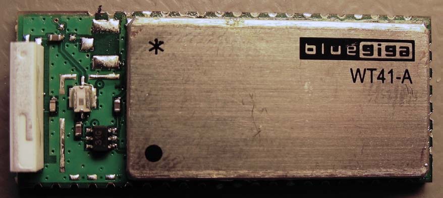
ADTS552 Internal Photographs PCB Mounted in Enclosure Antenna COAX Cable PCB to Front Panel PCB Top Side – SMA Antenna Connector to Right (Approximately 140mm along short side) PCB Underside – Wireless Module to Left (Approximately 280mm along long side)

RF Exposure Info

Radio Test Report: TRA-026611-01-47-00A 58 Appendix G: General SAR test reduction and exclusion guidance KDB 447498 Section 4.3 General SAR test reduction and exclusion guidance For Standalone SAR exclusion consideration, when SAR Exclusion Threshold requirement in KDB 447498 is satisfied, standalone SAR evaluation for general population exposure conditions by measurement or numerical simulation is not required. The SAR Test Exclusion Threshold for 100 MHz to 6 GHz will be determined as follows. SAR Exclusion Threshold (SARET) = Step 1 + Step 2 Step 1 NT = [ (MP/TSD A ) * √ f GHz ] NT = Numeric Threshold (3.0 for 1-g SAR and 7.5 for 10-g SAR) MP = Max Power of channel (mW) (including tune-up tolerance) TSD A = Min Test separation Distance or 50 mm (whichever is lower) = 50 mm (in this case) We can transpose this formula to allow us to find the maximum power of a channel allowed and compare this to the measured maximum power. = [(NT x TSD A ) / √ f GHz ] For Distances Greater than 50 mm Step 2 applies Step 2 (TSD B – 50mm) * 10 Where: TSD B = Min Test separation Distance (mm) = 50 Note: Step 2 doesn’t apply here as the TSD A is less than 50 mm Radio Test Report: TRA-026611-01-47-00A 59 Operating Frequency 2.402 GHz SARET = [(3.0 x 50) / √2.402] SARET = 96.8 mW Operating Frequency 2.441 GHz SARET = [(3.0 x 50) / √2.441] SARET = 96.0 mW Operating Frequency 2.480 GHz SARET = [(3.0 x 50) / √2.480] SARET = 95.3 mW Channel Frequency (MHz) EIRP (mW) SAR Exclusion Threshold (mW) SAR Evaluation 2402 23.9 96.8 Not Required 2441 38.1 96.0 Not Required 2480 31.3 95.3 Not Required Note: EIRP is calculated from maximum radiated field strength. Therefore standalone SAR evaluation for general population exposure conditions by measurement or numerical simulation is not required. Radio Test Report: TRA-026611-01-47-00A 60 Appendix H: MPE Calculation Prediction of MPE limit at a given distance For purposes of these requirements mobile devices are defined by the FCC and Industry Canada as transmitters designed to be used in other than fixed locations and to generally be used in such a way that a separation distance of at least 20 centimeters is normally maintained between radiating structures and the body of the user or nearby persons. These devices are normally evaluated for exposure potential with relation to the MPE limits. As the 20cm separation specified under FCC and Industry Canada rules may not be achievable under normal operation of the EUT, an RF exposure calculation is needed to show the minimum distance required to be less than the power density limit, as required under FCC and Industry Canada rules. Equation from IEEE C95.1 Where: S = power density R = distance to the centre of radiation of the antenna EIRP = EUT Maximum power FCC Result Prediction Frequency (MHz) Maximum EIRP (mW) Power density limit (S) (mW/cm 2 ) Distance (R) cm required to be less than 0.98 mW/cm 2 2441 38.1 1.0 1.8 IC Result Prediction Frequency (MHz) Maximum EIRP (W) Exemption limit (W) RF Exposure 2441 0.0381 2.7 Not required Note: EIRP is calculated from maximum radiated field strength. ππ4 arranged- re 4 2 S EIRP R R EIRP S ==

Test Report

A RADIO TEST REPORT FOR DRUCK LTD T/A GE MEASUREMENT & CONTROL ON ADTS DOCUMENT NO. TRA-026611-01-47-00B Total number of pages: 61 TRaC Wireless Test Report : TRA-026611-01-47-00B Applicant : Druck Ltd t/a GE Measurement & Control Apparatus : ADTS Specification(s) : CFR47 Part 15.247 & RSS-247 Issue 1 FCCID : 2AAVWADTS552F-01 Certification Number : 12097A-ADTS552F01 Purpose of Test : Certification Authorised by : : Radio Product Manager Issue Date : 25 th August 2015 Authorised Copy Number : PDF TRaC Global Test Report: TRA-026611-01-47-00B 3 Contents Section 1: Introduction 4 1.1 General 4 1.2 Tests Requested By 5 1.3 Manufacturer 5 1.4 Apparatus Assessed 5 1.5 Test Result Summary 6 1.6 Notes Relating To the Assessment 7 1.7 Deviations from Test Standards 7 Section 2: Measurement Uncertainty 8 2.1 Measurement Uncertainty Values 8 Section 3: Modifications 10 3.1 Modifications Performed During Assessment 10 Section 4 General Test Procedures 11 4.1 Radiated Test Setup and Procedures 11 4.2 AC Powerline Conducted Emissions Test Setup and Procedures 12 4.3 Antenna Port Conducted Emissions 12 4.4 Power Supply Variation 13 4.5 Thermal Variation 13 4.6 Time Domain Measurements 13 Appendix A: Formal Emission Test Results 14 A1 Transmitter Peak Output Power 15 A2 RF Antenna Conducted Spurious Emissions 16 A3 Radiated Electric Field Emissions 18 A4 Power Line Conducted Emissions 22 A5 20 dB Bandwidth 24 A6 Carrier Frequency Separation 25 A7 Hopping frequencies 26 A8 Channel Occupancy 27 A9 Unintentional Radiated Electric Field Emissions 28 Appendix B: Supporting Graphical Data 30 Appendix C: Additional Test and Sample Details 48 Appendix D: Additional Information 54 Appendix E: Calculation of the duty cycle correction factor 55 Appendix F: Photographs and Figures 56 Appendix G: General SAR test reduction and exclusion guidance 58 Appendix H: MPE Calculation 60 Radio Test Report: TRA-026611-01-47-00B 4 Section 1: Introduction 1.1 General This report contains an assessment of an apparatus against Electromagnetic Compatibility Standards based upon tests carried out on samples submitted to the Laboratory. Test performed by: TRaC Global [ ] Unit E South Orbital Trading Park Hedon Road Hull, HU9 1NJ. United Kingdom. Telephone: +44 (0) 1482 801801 Fax: +44 (0) 1482 801806 TRaC Global [X] Unit 1 Pendle Place Skelmersdale West Lancashire, WN8 9PN United Kingdom Telephone: +44 (0) 1695 556666 Fax: +44 (0) 1695 577077 Email: [email protected] Web site: http://www.tracglobal.com Tests performed by: A Tosif - D Winstanley Report author: A Tosif This report must not be reproduced except in full without prior written permission from TRaC Global. Radio Test Report: TRA-026611-01-47-00B 5 1.2 Tests Requested By This testing in this report was requested by: Druck Ltd t/a GE Measurement & Control Fir Tree Lane Groby Leicester Leicestershire LE6 0FH United Kingdom 1.3 Manufacturer As above 1.4 Apparatus Assessed The following apparatus was assessed between 21 st May 2015 and 10 th July 2015. • Name: ADTS • Serial Number: 5520012 • Model Number: ADTS552F • Software Revision: DK429_V02.00.16 • Build Level / Revision Number: Not Applicable The EUT is device containing a FHSS Bluetooth module operating with standard and enhanced data rates. Radio Test Report: TRA-026611-01-47-00B 6 1.5 Test Result Summary Full details of test results are contained within Appendix A. The following table summarises the results of the assessment. The statements relating to compliance with the standards below apply ONLY as qualified in the notes and deviations stated in sections 1.6 to 1.7 of this test report. Full details of test results are contained within Appendix A. The following table summarises the results of the assessment. Test Type Regulation Measurement standard Result Title 47 of the CFR: Part 15 Subpart (c) RSS Gen Issue 4, Nov 2014 and RSS – 247 Issue 1, May 2015 Radiated spurious emissions (Restricted bands) 15.247 - ANSI C63.10:2013 Pass Conducted spurious emissions (Non-restricted bands) 15.247 RSS – 247 Section 5.5 ANSI C63.10:2013 Pass AC Power conducted emissions 15.207 RSS Gen Section 8.8 ANSI C63.10:2013 Pass 20dB Bandwidth and Channel Spacing 15.247(a)(1)(i) RSS – 247 Section 5.1(1)(2) ANSI C63.10:2013 Pass Conducted Carrier Power 15.247(b)(2) RSS – 247 Section 5.4(2) ANSI C63.10:2013 Pass Hopping Frequencies 15.247(a)(1) RSS – 247 Section 5.1(4) ANSI C63.10:2013 Pass Channel Occupancy 15.247(a)(1)(i) RSS – 247 Section 5.1(4) ANSI C63.10:2013 Pass Unintentional Radiated Spurious Emissions 15.109 RSS – Gen Section 7.1 ANSI C63.10:2013 Pass Antenna requirements 15.203 - 15.203 Pass Abbreviations used in the above table: Mod : Modification RSS : Radio Standards Specification CFR : Code of Federal Regulations ANSI : American National Standards Institution REFE : Radiated Electric Field Emissions PLCE : Power Line Conducted Emissions Radio Test Report: TRA-026611-01-47-00B 7 1.6 Notes Relating To the Assessment With regard to this assessment, the following points should be noted: The results contained in this report relate only to the items tested and were obtained in the period between the date of initial receipt of samples and the date of issue of the report. The apparatus was set up and exercised using the configurations, modes of operation and arrangements defined in this report only. Particular operating modes, apparatus monitoring methods and performance criteria required by the standards tested to have been performed except where identified in Section 1.7 of this test report (Deviations from Test Standards). For emissions testing, throughout this test report, “Pass” indicates that the results for the sample as tested were below the specified limit (refer also to Section 2, Measurement Uncertainty). Where relevant, the apparatus was only assessed using the monitoring methods and susceptibility criteria defined in this report. All testing with the exception of testing at the Open Area Test Site was performed under th…

Text truncated - open the document above for the full version.

Test Setup Photos

Radio Test Report: TRA-026611-01-47-00A 56 Appendix F: Photographs and Figures The following photographs were taken of the test samples: 1. Radiated electric field emissions arrangement: overview 2. Radiated electric field emissions arrangement: close up Radio Test Report: TRA-026611-01-47-00A 57 Photograph 1 Photograph 2

Contact Information

Applicant

Matthew T Concannon(Mr)
[email protected]+44 116 231 7444Fax: +44 116 231 7101

Test Firm

Element Materials Technology Warwick LtdStewart Barrowclough
[email protected]01695556666Fax: 01695557077

Technical Specifications

#Rule PartsFrequency RangePower Output
115C2.40 GHz - 2.48 GHz20.70 mW
Confidentiality
Long Term
Grant Notes
RF Output Power is Conducted. The antenna(s) used for this transmitter must be installed to provide a separation distance of at least 20 cm from all persons and must not be co-located or operating in conjunction with any other antenna or transmitter, except in accordance with FCC multi-transmitter product guidelines. This equipment supports data transmission rates of 1Mbps, 2Mbps and 3Mbps.

Other Applications from Druck Ltd

ADTS Touch - FCC ID 2AAVWADTSTOUCH-01 - Druck Ltd
2AAVWADTSTOUCH-01

ADTS Touch

Feb 02, 2015

Equipment Class

DSS - Part 15 Spread Spectrum Transmitter