2AAXVLRTNTMOD1UWB Modular Radio
ABG TAG & TRAQ LLC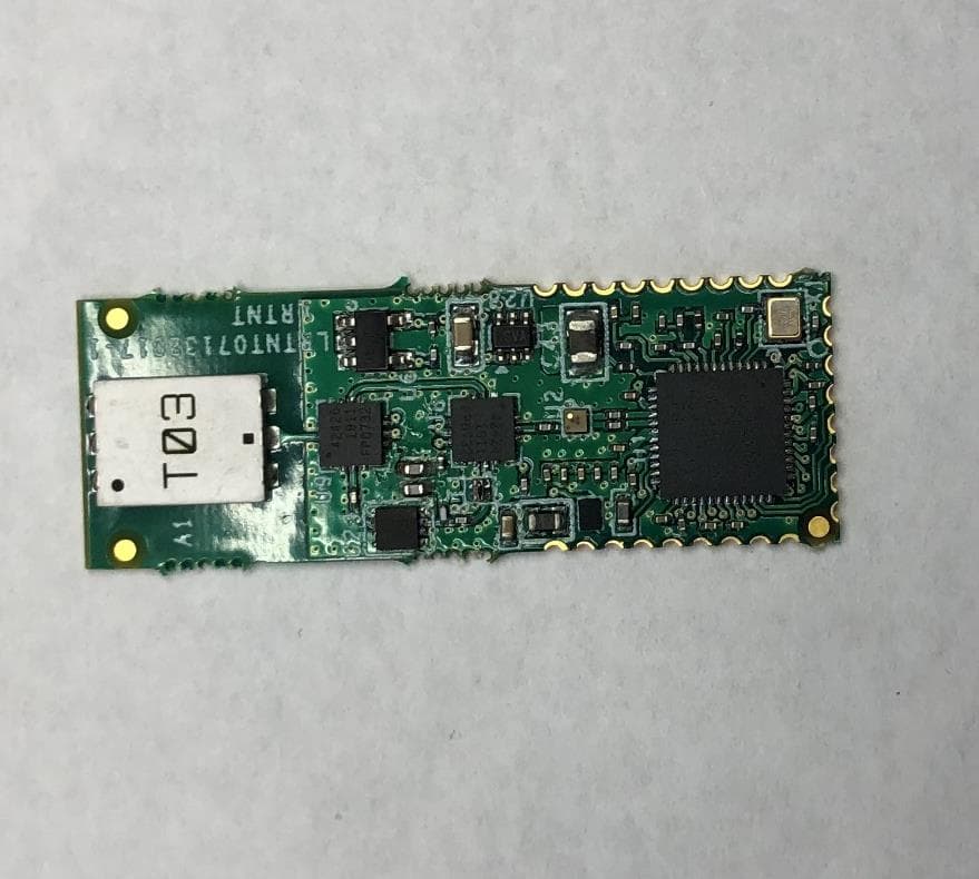
Click to zoom
Application Details
- Equipment Class
- UWB - Ultra Wideband Transmitter
- Date of Grant
- Oct 21, 2020
- Application Purpose
- Original Equipment
- Date of Application
- Oct 13, 2020
- Equipment Note
- UWB Modular Radio
- Frequency Range
- 3522.00000000 - 4582.90000000
- Company
- ABG TAG & TRAQ LLC
- Country
- United States
Documents & Files
Document Text
Text extracted from the exhibit documents filed with the FCC. Open a document above to read the original.
Users Manual
2020 Alltraq UWB LRT Modular Radio Manual Device Name: UWB Radio 2 Copyright Statement © 2020 ABG Tag and Traq, Inc. All rights reserved. This material may not be reproduced, displayed, modified or distributed without the express prior written permission of the copyright holder. For permission, contact: ABG Tag and Traq, Inc. 1507 Capital Ave, Suite 101 Plano, TX 75074 Phone: 903-316-7417 Contact form: http://www.americanbiomedicalgroup.net/contact 3 This page intentionally left blank. ©2020 ABG Tag and Traq, Inc. ABG Tag and Traq reserve the right to change this manual and its contents without notice. 4 Table of Contents Copyright Statement...................................................................... Error! Bookmark not defined. Regulatory and Compliance Information .....................................................................................5 FCC Compliance .........................................................................................................................5 Department of Communications—Canada...................................................................................6 Canadian Compliance Statement .................................................................................................6 Module Operation and Use ..........................................................................................................7 Overview ....................................................................................................................................7 Transmitter with External Frequency Selection Controls .............................................................7 Warranty Information ................................................................................................................ 10 5 Regulatory and Compliance Information FCC Compliance FCC Certification number: 2AAXVLRTNTMOD1 Manufacturer: ABG Tag and Traq, Inc. 510 E. Memorial Road, Suite B-1 Oklahoma City, OK 73114 USA This device complies with Part 15 rules of FCC Rules and Industry Canada licenses-exempt RSS Standard(s). Operation is subject to the following two conditions: 1. This device may not cause harmful interference, and 2. This device just accepts any interference received, including interference that may cause undesired operation. This equipment has been tested and found to comply with the limits of a UWB transmitter device, pursuant to Part 15 of the FCC Rules. These limits are designed to provide reasonable protection against harmful interference when the equipment is operated in a residential environment. This equipment generates, uses, and radiates radio frequency energy, and if not installed and used in accordance with the instructions, may cause harmful interference. However, there is no guarantee that interference will not occur. NO UNAUTHORIZED MODIFICATIONS 47 CFR §15.21 CAUTION: This equipment may not be modified, altered, or changed in any way without permission from ABG Tag and Traq, Inc. Unauthorized modification may void the equipment authorization from the FCC and will void the Alltraq warranty. 6 Department of Communications—Canada Certification number: 11400A-LRTNTMOD1 PMN: UWB Radio Canadian Compliance Statement This Class B Digital apparatus meets all the requirements of the Canadian Interference-Causing Equipment Regulations. Cet appareil numerique de la classe B respecte les exigences du Reglement sur le material broilleur du Canada. This device complies with Class B Limits of Industry Canada. Operation is subject to the following two conditions: (1) this device may not cause harmful interference, and (2) this device just accepts any interference received, including interference that may cause undesired operation. Le présent appareil est conforme aux CNR d'Industrie Canada applicables aux appareils radio exempts de licence. L'exploitation est autorisée aux deux conditions suivantes : (1) l'appareil ne doit pas produire de brouillage, et (2) l'utilisateur de l'appareil doit accepter tout brouillage radio électrique subi, même si le brouillage est susceptible d'en compromettre le fonctionnement. ABG Tag and Traq UWB Module is certified to the requirements of RSS-220 for Ultra- Wideband transmitters pertaining to Radiated Emissions and Peak Emissions. 7 Module Operation and Use Overview The primary use of the module is to provide active RFID location capabilities to a battery powered device. The module is intended to be soldered on to a device’s circuit board. The modules will not be sold without the accompanying circuit board with controller circuit. The modules are capable of ranging to each other to within 1 foot of accuracy. The UWB module is a self-regulated device that accepts a 2.8V to 3.6V range. It uses 15mA to 200mA of current to power the module during idle and active times. The module can also be put to sleep requiring less than 5uA of current. The module requires an external controller to set its configuration and to put it in the different operating modes and to select channels. The primary means of communication with the module is by SPI bus. It also uses interrupt lines to indicate to the external controller when an event has occurred. A pin is also provided to wake the module from sleep mode. The module uses the DecaWave DW1000 UWB radio. The module is certified to use channel 1 at 3.5GHz center frequency and channel 4 at 4GHz center frequency as defined in the DW1000 UWB radio’s datasheet. The Channels with frequencies outside of 3.5GHz and 4GHz center frequencies shall not be used by this module. All communication requirement and register settings are defined in the DW1000 datasheet. Frequency is fixed by manufacturer at 3.5GHz and 4GHz with 500MHz and greater bandwidths. The module’s pins are defined in the module’s schematic. The RF output of channel 1 is from 3.1 GHz to 3.91 GHz. The RF output of channel 4 is from 3.48 GHz to 4.46 GHz. The module has an embedded antenna. The antenna cannot be changed with …
Text truncated - open the document above for the full version.
Cover Letter(s)
October 2, 2020 Office of Engineering and Technology Federal Communications Commission Re: FCC ID: 2AAXVLRTNTMOD1 Applicant: ABG Tag and Traq, Inc Dear Office of Engineering and Technology: This letter is meant to address any potential concerns regarding requirement 15.519 and provide documentation on how this requirement is fulfilled. According to “15.519, Technical Requirements for UWB Handheld systems”: (a) UWB devices operating under the provisions of this section must be handheld, i.e., they are relatively small devices that are primarily handheld while being operated and do not employ a fixed infrastructure. (1) A UWB device operating under the provisions of this section shall transmit only when it is sending information to an associated receiver. The UWB intentional radiator shall cease transmission within 10 seconds unless it receives an acknowledgement from the associated receiver that its transmission is being received. An acknowledgment of reception must continue to be received by the UWB intentional radiator at least every 10 seconds or the UWB device must cease transmitting. This module is primarily hand-held and may operate indoors or outdoors; its operation is limited under the provisions of section 15.519. The UWB transmitter operates as part of a system in which it sends short duration UWB packets to one or more receivers. The transmitter’s cycle of operation is as follows: 1) the transmitter’s microcontroller begins in a non-transmitting sleep state 2) the transmitter transitions to an active state, in which it sends a short UWB packet of fixed duration of 715 microseconds 3) the transmitter microcontroller ceases the transmission and returns to a sleep state. An oscilloscope screen capture of the 715 microsecond packet is shown in the figure below. Figure 1. Ultra-wideband Packet Per the 15.519(a)(1) requirement, the UWB transmitter is allowed to operate up to 10 seconds after which it must cease its transmission if it has not received an acknowledgement from the associated receiver. As demonstrated, the UWB transmitter will automatically cease its transmission after only 715 microseconds, meeting the requirement in much less than the allowed 10 seconds. The user’s manual has been updated to be consistent with this document. The updated manual states that the module is a Single Limited Modular Transmitter and addresses the appropriate requirements. Sincerely, Sujit Ravindran Principal Electrical Engineer American Biomedical Group Tag & Traq, Inc. 1507 Capital Ave / Plano, TX. 75074 Email: [email protected] phone: 903.267.4088
Cover Letter(s)
(d) 4. Operational description
External Photos
www.nemko.com Nemko Canada Inc., a testing laboratory, is accredited by the Standards Council of Canada. The tests included in this report are within the scope of this accreditation Internal photos.docx; Date: May 2013 SCC Accredited LAB LAB Accrédité CCN TM ONE WORLDOURAPPROVAL External photos -2RADWL Date of issue: March 17, 2020 Applicant: ABG Tag and Traq, Inc. 510 E.Memorial Road, Suite B-1 Oklahoma City, OK. 73114 Product: Indoor Ultra-wideband transmitter module Model: LRTNTMOD1 Model variant: FCC ID: 2AAXVLRTNTMOD1 IC Registration number: 11400A-LRTNTMOD1 Section 1: Internal photos Report reference ID: -2RADWL Page 2 of 3 Section 1. Internal photos 1.1 Top general view Section 1: Internal photos Report reference ID: -2RADWL Page 3 of 3 1.2 PCB bottom view
ID Label/Location Info
www.nemko.com Nemko Canada Inc., a testing laboratory, is accredited by the Standards Council of Canada. The tests included in this report are within the scope of this accreditation Internal photos.docx; Date: May 2013 SCC Accredited LAB LAB Accrédité CCN TM ONE WORLDOURAPPROVAL Labels and Label Locations Date of issue: March 17, 2020 Applicant: ABG Tag and Traq, Inc. 510 E.Memorial Road, Suite B-1 Oklahoma City, OK. 73114 Product: Indoor Ultra-wideband transmitter module Model: LRTNTMOD1 Model variant: FCC ID: 2AAXVLRTNTMOD1 IC Registration number: 11400A-LRTNTMOD1 Section 1: Internal photos Report reference ID: -2RADWL Page 2 of 2 1.1 Top general view PCB Bottom side of label Silkscreen view of the label and Label location on the board
Internal Photos
www.nemko.com Nemko Canada Inc., a testing laboratory, is accredited by the Standards Council of Canada. The tests included in this report are within the scope of this accreditation Internal photos.docx; Date: May 2013 SCC Accredited LAB LAB Accrédité CCN TM ONE WORLDOURAPPROVAL Internal photos -2RADWL Date of issue: March 17, 2020 Applicant: ABG Tag and Traq, Inc. 510 E.Memorial Road, Suite B-1 Oklahoma City, OK. 73114 Product: Indoor Ultra-wideband transmitter module Model: LRTNTMOD1 Model variant: FCC ID: 2AAXVLRTNTMOD1 IC Registration number: 11400A-LRTNTMOD1 Section 1: Internal photos Report reference ID: -2RADWL Page 2 of 3 Section 1. Internal photos 1.1 Top general view Section 1: Internal photos Report reference ID: -2RADWL Page 3 of 3 1.2 PCB bottom view
RF Exposure Info
ONE WORLD OUR APPR OVAL www.nemko.com KDB 447498 D01 General RF Exposure Guidance v05r02 (February 7, 2014) 1. Declaration of RF exposure compliance for exemption from routine evaluation limits FCC ID: 2AAXVLRTNTMOD1 Model number: LRTNTMOD1 Manufacturer: ABG Tag and Traq, Inc. 4.3.1. Standalone SAR test exclusion considerations: During normal operation, user extremities can come within 20 cm of the internal antenna and therefore product is considered as “Portable”. The 1-g and 10-g SAR test exclusion thresholds for 100 MHz to 6 GHz at Test separation distances ≤ 50 mm are determined by: [(max. power of channel, including tune-up tolerance, mW) ÷ (min. test separation distance, mm)] × [ √ 퐹(퐺퐻푧)] ≤ 3.0 for 1-g SAR and ≤ 7.5 for 10-g extremity SAR, where f(GHz) is the RF channel transmit frequency in GHz Power and distance are rounded to the nearest mW and mm before calculation The result is rounded to one decimal place for comparison The test exclusions are applicable only when the minimum test separation distance is ≤ 50 mm and for transmission frequencies between 100 MHz and 6 GHz. When the minimum test separation distance is < 5 mm, a distance of 5 mm according to 5) in section 4.1 is applied to determine SAR test exclusion 3.418 GHz – Operation: Calculation based on the above formula: Separation Distance = 5 mm Radiated Output Power = -4.89 dBm = 0.32 mW Frequency = 3.42GHz Calculation = (0.32÷5)× √ 3.42 = 0.12 < 3 The calculation is below the threshold, therefore the product exempt from the SAR test requirements 4.35GHz – Operation: Calculation based on the above formula: Separation Distance = 5 mm Radiated Output Power = -1 dBm = 0.79 mW Frequency = 3.42GHz Calculation = (0.79÷5)× √ 3.42 = 0.54 < 3 The calculation is below the threshold, therefore the product exempt from the SAR test requirements NOTE: 3.418GHz operation: 71.9 dBμV/m (at .5m) – 20 log (3/.5) (adjusted to 3m) + 20 log (50/1) (adjust for total power output over 50MHz BW) – 95.23 (to convert to dBm) : therefore EIRP = -4.89dBm for 3.5GHz operation NOTE: 4.35 GHz operation: 69.8dBμV/m (at .5m) – 20 log (3/.5) (adjusted to 3m) + 20 log (100/1) (adjust for total power output over 50MHz BW) – 95.23 (to convert to dBm) : therefore EIRP = -1 dBm for 3.5GHz operation 2. Attestation ATTESTATION: I attest that the testing was performed or supervised by me; that the test measurements were made in accordance with the above-mentioned departmental standard(s), and that the radio equipment identified in this application has been subject to all applicable test conditions specified in the departmental standards and all of the requirements of the standards have been met. Signature: Date: August 20, 2020 Name: Chip Fleury
Test Report
www.nemko.com Nemko USA Inc., a testing laboratory, is accredited by NVLAP. The tests included in this report are within the scope of this accreditation. Test report 392836-1R2TRFWL Date of issue: September 9, 2020 Applicant: ABG Tag and Traq, Inc. Product: Indoor Ultra-wideband transmitter module Model: LRTNTMOD1 FCC ID IC ID 2AAXVLRTNTMOD1 11400A-LRTNTMOD1 Specifications: FCC 47 CFR Part 15, Subpart F – §15.519 Industry Canada RSS-220, Issue 1 + Amendment 1 O N E W O R L D O U R A P P R O V A L Report reference ID: 392836-1R2TRFWL Page 2 of 30 Lab and test locations Company name Nemko USA Inc. Address 2210 Faraday Ave, Suite 150 City Carlsbad State California Postal code 92008 Country USA Telephone +1 760 444 3500 Website www.nemko.com FCC Site Number Test Firm Registration Number: 392943 Designation Number: US5058 ISED Test Site 2040B-3 Tested by James Cunningham, Wireless Supervisor Reviewed by Juan M Gonzalez, EMC & Wireless Divisions Manager Review date September 9, 2020 Reviewer signature Limits of responsibility Note that the results contained in this report relate only to the items tested and were obtained in the period between the date of initial receipt of samples and the date of issue of the report. This test report has been completed in accordance with the requirements of ISO/IEC 17025. All results contain in this report are within Nemko USA’s ISO/IEC 17025 accreditation. This report must not be used by the client to claim product certification, approval, or endorsement by NVLAP, NIST, or any agency of the U.S. Government. Copyright notification Nemko USA Inc. authorizes the applicant to reproduce this report provided it is reproduced in its entirety and for use by the company’s employees only. Any use which a third party makes of this report, or any reliance on or decisions to be made based on it, are the responsibility of such third parties. Nemko USA Inc. accepts no responsibility for damages, if any, suffered by any third party as a result of decisions made or actions based on this report. © Nemko USA Inc. Report reference ID: 392836-1R2TRFWL Page 3 of 30 Table of Contents Table of Contents ......................................................................................................................................................................................................... 3 Report summary ................................................................................................................................................................................. 4 1.1 Test specifications ................................................................................................................................................................................................................. 4 1.2 Test methods ......................................................................................................................................................................................................................... 4 1.3 Exclusions ............................................................................................................................................................................................................................... 4 1.4 Statement of compliance...................................................................................................................................................................................................... 4 1.5 Test report revision history .................................................................................................................................................................................................. 4 Summary of test results ...................................................................................................................................................................... 5 2.1 FCC Part 15.519 / RSS-220. ................................................................................................................................................................................................... 5 2.2 Operating modes investigated. ............................................................................................................................................................................................ 5 Equipment under test (EUT) details ..................................................................................................................................................... 6 3.1 Applicant ................................................................................................................................................................................................................................ 6 3.2 Manufacturer......................................................................................................................................................................................................................... 6 3.3 Sample information............................................................................................................................................................................................................... 6 3.4 EUT information .................................................................................................................................................................................................................... 6 3.5 EUT exercise and monitoring details ................................................................................................................................................................................... 6 Engineering considerations ................................................................................................................................................................. 7 4.1 Modifications incorporated in the EUT ...............................................…
Text truncated - open the document above for the full version.
Test Setup Photos
Report reference ID: 392836 -1TRFWL (LRNTMOD1 15.517 RSS-220) Model: LRNTMOD1 FCC ID: 2AAXVLRNTMOD1 IC ID: 11400A-LRNTMOD1 Section 1. Test Setup Photos 1.1 Definition of UWB setup Report reference ID: 392836 -1TRFWL (LRNTMOD1 15.517 RSS-220) Model: LRNTMOD1 FCC ID: 2AAXVLRNTMOD1 IC ID: 11400A-LRNTMOD1 1.2 Radiated emissions < 960 MHz Report reference ID: 392836 -1TRFWL (LRNTMOD1 15.517 RSS-220) Model: LRNTMOD1 FCC ID: 2AAXVLRNTMOD1 IC ID: 11400A-LRNTMOD1 1.3 Radiated emissions > 960 MHz
Contact Information
Applicant
James K Burgess III(CEO)
Test Firm
Nemko USA, Inc. - San Diego EMC DivisionJan Blomgren
[email protected]760-444-3500
Technical Specifications
| # | Rule Parts | Frequency Range | Power Output |
|---|---|---|---|
| 2 | 15F | 3.52 GHz - 4.58 GHz | - |
Other Applications from ABG TAG & TRAQ LLC
2AAXVTNTMOD1
Nov 09, 2015Ultra-wideband transmitter module
Equipment Class
UWB - Ultra Wideband Transmitter