2AAXVTNTMOD1Ultra-wideband transmitter module
ABG TAG & TRAQ LLC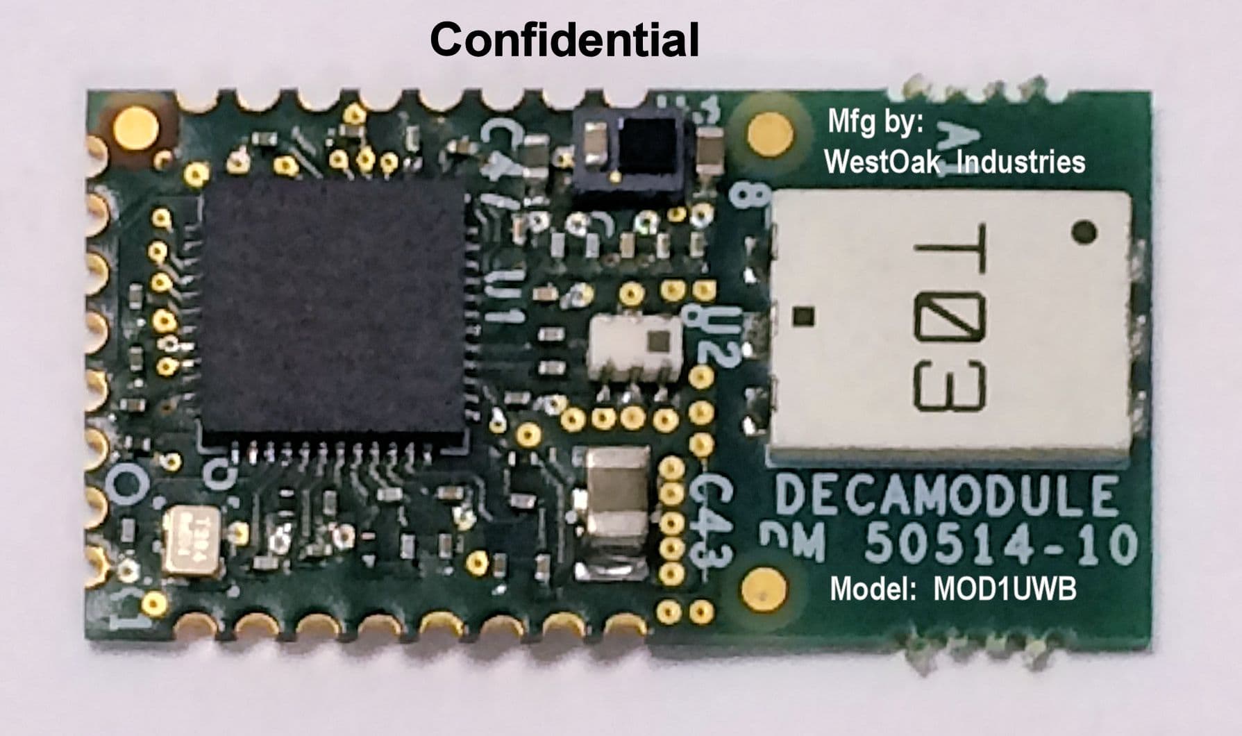
Click to zoom
Application Details
- Equipment Class
- UWB - Ultra Wideband Transmitter
- Date of Grant
- Nov 09, 2015
- Application Purpose
- Original Equipment
- Date of Application
- Jul 16, 2015
- Equipment Note
- Ultra-wideband transmitter module
- Frequency Range
- 3480.00000000 - 4460.00000000
- Company
- ABG TAG & TRAQ LLC
- Country
- United States
Documents & Files
Document Text
Text extracted from the exhibit documents filed with the FCC. Open a document above to read the original.
Users Manual
2015 Alltraq UWB Modular Radio Manual 2 Copyright Statement © 2015 ABG Tag and Traq, LLC. All rights reserved. This material may not be reproduced, displayed, modified or distributed without the express prior written permission of the copyright holder. For permission, contact: ABG Tag and Traq LLC 2300 Joe Ramsey Blvd. E Greenville, TX 75401 Phone: 903-316-7417 Contact form: http://www.americanbiomedicalgroup.net/contact 3 This page intentionally left blank. ©2015 ABG Tag and Traq, LLC. ABG Tag and Traq reserve the right to change this manual and its contents without notice. 4 Table of Contents Copyright Statement ....................................................................................................................... 2 Regulatory and Compliance Information ........................................................................................ 5 FCC Compliance ............................................................................................................................. 5 Department of Communications—Canada ..................................................................................... 6 Canadian Compliance Statement .................................................................................................... 6 Module Operation and Use ............................................................................................................. 7 Overview ......................................................................................................................................... 7 Transmitter with External Frequency Selection Controls ............................................................... 7 Warranty Information ..................................................................................................................... 9 5 Regulatory and Compliance Information FCC Compliance FCC Certification number: 2AAXVTNTMOD1 Manufacturer: ABG Tag and Traq, LLC. 2300 Joe Ramsey Blvd. E. Greenville, TX 75401 USA This device complies with Part 15 rules of FCC Rules and Industry Canada licenses-exempt RSS Standard(s). Operation is subject to the following two conditions: 1. This device may not cause harmful interference, and 2. This device just accepts any interference received, including interference that may cause undesired operation. This equipment has been tested and found to comply with the limits of a UWB transmitter device, pursuant to Part 15 of the FCC Rules. These limits are designed to provide reasonable protection against harmful interference when the equipment is operated in a residential environment. This equipment generates, uses, and radiates radio frequency energy, and if not installed and used in accordance with the instructions, may cause harmful interference. However, there is no guarantee that interference will not occur. This equipment may only be operated indoors. Operation outdoors is in violation of 47 U.S.C. 301 and could subject the operator to serious legal penalties. NO UNAUTHORIZED MODIFICATIONS 47 CFR §15.21 CAUTION: This equipment may not be modified, altered, or changed in any way without permission from ABG Tag and Traq, LLC. Unauthorized modification may void the equipment authorization from the FCC and will void the Alltraq warranty. 6 Department of Communications—Canada Certification number: 11400A-TNTMOD1 Canadian Compliance Statement This Class B Digital apparatus meets all the requirements of the Canadian Interference-Causing Equipment Regulations. Cet appareil numerique de la classe B respecte les exigences du Reglement sur le material broilleur du Canada. This device complies with Class B Limits of Industry Canada. Operation is subject to the following two conditions: (1) this device may not cause harmful interference, and (2) t his device just accepts any interference received, including interference that may cause undesired operation. Le présent appareil est conforme aux CNR d'Industrie Canada applicables aux appareils radio exempts de licence. L'exploitation est autorisée aux deux conditions suivantes : (1) l'appareil ne doit pas produire de brouillage, et (2) l'utilisateur de l'appareil doit accepter tout brouillage radio électrique subi, même si le brouillage est susceptible d'en compromettre le fonctionnement. ABG Tag and Traq UWB Module is certified to the requirements of RSS-220 for Ultra Wide Band transmitters pertaining to Radiated Emissions and Peak Emissions. 7 Module Operation and Use Overview The primary use of the module is to provide active RFID location capabilities to a battery powered device. The module is intended to be soldered on to a device’s circuit board. The modules will not be sold without the accompanying circuit board with controller circuit. The modules are capable of ranging to each other to within 1 foot of accuracy. The UWB module is a self regulated device that accepts a 2.8V to 3.6V range. It uses 15mA to 200mA of current to power the module during idle and active times. The module can also be put to sleep requiring less than 5uA of current. The module requires an external controller to set its configuration and to put it in the different operating modes and to select channels. The primary means of communication with the module is by SPI bus. It also uses interrupt lines to indicate to the external controller when an event has occurred. A pin is also provided to wake the module from sleep mode. The module uses the decaWave DW1000 UWB radio. The module is certified to use channel 1 at 3.5GHz center frequency and channel 4 at 4GHz center frequency as defined in the DW1000 UWB radio’s datasheet. The Channels with frequencies outside of 3.5GHz and 4GHz center frequencies shall not be used by this module. All communication requirement and register settings are defined in the DW1000 datasheet. Frequency is fixed by manufacturer at 3.5GHz and 4GHz with 500MHz and greater bandwidths. The module’s pins are defined in the module’s schematic. The RF output of channel 1 …
Text truncated - open the document above for the full version.
Users Manual
© DecaWave Ltd 2014 Version 2.02 Page 1 of 215 DW1000 USER MANUAL HOW TO USE, CONFIGURE AND PROGRAM THE DW1000 UWB TRANSCEIVER This document is subject to change without notice DW1000 USER MANUAL DW1000 User Manual © DecaWave Ltd 2014 Version 2.02 Page 2 of 215 Table of Contents LIST OF FIGURES ........................................................ 3 LIST OF TABLES .......................................................... 4 1 INTRODUCTION ................................................. 7 1.1 ABOUT THE DW1000 ...................................... 7 1.2 ABOUT THIS DOCUMENT .................................... 7 2 OVERVIEW OF THE DW1000 .............................. 9 2.1 INTRODUCTION ................................................ 9 2.2 INTERFACING TO THE DW1000 .......................... 9 2.3 DW1000 OPERATIONAL STATES ...................... 13 2.4 POWER ON RESET (POR) ................................ 17 2.5 DEFAULT CONFIGURATION ON POWER UP .......... 19 3 MESSAGE TRANSMISSION ................................ 23 3.1 BASIC TRANSMISSION ...................................... 23 3.2 TRANSMISSION TIMESTAMP .............................. 24 3.3 DELAYED TRANSMISSION ................................. 24 3.4 EXTENDED LENGTH DATA FRAMES ..................... 25 3.5 HIGH SPEED TRANSMISSION ............................. 26 4 MESSAGE RECEPTION ....................................... 29 4.1 BASIC RECEPTION ........................................... 29 4.2 DELAYED RECEIVE ........................................... 32 4.3 DOUBLE RECEIVE BUFFER................................. 32 4.4 LOW-POWER LISTENING .................................. 36 4.5 LOW-POWER SNIFF MODE .............................. 38 4.6 DIAGNOSTICS ................................................ 41 4.7 ASSESSING THE QUALITY OF RECEPTION AND THE RX TIMESTAMP ................................................................ 41 5 MEDIA ACCESS CONTROL (MAC) HARDWARE FEATURES ................................................................. 45 5.1 CYCLIC REDUNDANCY CHECK ............................. 45 5.2 FRAME FILTERING ........................................... 45 5.3 AUTOMATIC ACKNOWLEDGEMENT .................... 47 5.4 TRANSMIT AND AUTOMATICALLY WAIT FOR RESPONSE 50 6 OTHER FEATURES OF THE DW1000 ................... 51 6.1 EXTERNAL SYNCHRONISATION ........................... 51 6.2 EXTERNAL POWER AMPLIFICATION .................... 54 6.3 USING THE ON-CHIP OTP MEMORY ................... 54 6.4 MEASURING IC TEMPERATURE AND VOLTAGE ...... 58 7 THE DW1000 REGISTER SET .............................. 59 7.1 REGISTER MAP OVERVIEW ................................ 59 7.2 DETAILED REGISTER DESCRIPTION ...................... 61 8 DW1000 CALIBRATION ................................... 185 8.1 IC CALIBRATION – CRYSTAL OSCILLATOR TRIM ... 185 8.2 IC CALIBRATION – TRANSMIT POWER AND SPECTRUM 187 8.3 IC CALIBRATION – ANTENNA DELAY ................. 190 9 OPERATIONAL DESIGN CHOICES WHEN EMPLOYING THE DW1000....................................... 193 9.1 OPERATING RANGE ....................................... 193 9.2 CHANNEL AND BANDWIDTH SELECTION ............. 193 9.3 CHOICE OF DATA RATE, PREAMBLE LENGTH AND PRF 193 9.4 POWER CONSUMPTION .................................. 194 9.5 NODE DENSITY AND AIR UTILISATION ................ 194 9.6 LOW DUTY CYCLE - AIR TIME ............................ 195 9.7 LOCATION SCHEMES ...................................... 196 9.8 GENERAL CONSIDERATIONS............................. 197 10 APPENDIX 1: THE IEEE 802.15.4 UWB PHYSICAL LAYER ..................................................................... 199 10.1 FRAME STRUCTURE OVERVIEW ........................ 199 10.2 DATA MODULATION SCHEME .......................... 199 10.3 SYNCHRONISATION HEADER MODULATION SCHEME 200 10.4 PHY HEADER ............................................... 201 10.5 UWB CHANNELS AND PREAMBLE CODES ........... 202 10.6 ADDITIONAL DETAILS ON THE STANDARD ........... 203 11 APPENDIX 2: THE IEEE 802.15.4 MAC LAYER ... 204 11.1 GENERAL MAC MESSAGE FORMAT .................. 204 11.2 THE FRAME CONTROL FIELD IN THE MAC HEADER 205 11.3 THE SEQUENCE NUMBER FIELD ....................... 207 11.4 MAC LEVEL PROCESSING IN THE DW1000........ 208 12 APPENDIX 3: TWO-WAY RANGING ................. 209 13 APPENDIX 4: ABBREVIATIONS AND ACRONYMS 211 14 APPENDIX 5: REFERENCES .............................. 214 DW1000 User Manual © DecaWave Ltd 2014 Version 2.02 Page 3 of 215 List of Figures FIGURE 1: SPI READ AND WRITE TRANSACTIONS 10 FIGURE 2: SINGLE OCTET HEADER OF THE NON- INDEXED SPI TRANSACTION 11 FIGURE 3: EXAMPLE NON-INDEXED READ OF THE DEVICE ID REGISTER (0X00) 11 FIGURE 4: TWO OCTET HEADER OF THE SHORT INDEXED SPI TRANSACTION 11 FIGURE 5: EXAMPLE SHORT-INDEXED READ OF 3 RD AND 4 TH OCTETS OF REGISTER 0X00 12 FIGURE 6: THREE OCTET HEADER OF THE LONG INDEXED SPI TRANSACTION 12 FIGURE 7: EXAMPLE LONG-INDEXED WRITE OF ONE OCTET TO INDEX 310 OF THE TX BUFFER 12 FIGURE 8: DW1000 STATE DIAGRAM 14 FIGURE 9: TIMING DIAGRAM AND POWER PROFILE FOR COLD START POR 17 FIGURE 10: TRANSMIT FRAME FORMAT 23 FIGURE 11: BASIC TRANSMIT SEQUENCE 23 FIGURE 12: BASIC RECEIVE SEQUENCE 29 FIGURE 13: FLOW CHART FOR USING DOUBLE RX BUFFERING 35 FIGURE 14 : TRXOFF IN DOUBLE-BUFFERED MODE 36 FIGURE 15: LOW POWER LISTENING WITH TWO SLEEP TIMES 37 FIGURE 16: POWER PROFILE FOR LOW POWER LISTENING MODE WHERE NO FRAME IS RECEIVED 38 FIGURE 17: STATE TRANSITIONS DURING SNIFF MODE 39 FIGURE 18: POWER PROFILE FOR SNIFF WHERE A FRAME IS NOT RECEIVED 40 FIGURE 19: POWER PROFILE FOR SNIFF WHERE A FRAME IS RECEIVED 40 FIGURE 20: POWER PROFILE FOR LOW DUTY-CYCLE SNIFF WHERE A FRAME IS NOT RECEIVED 41 FIGURE 21: ESTIMATED RX LEVEL VERSUS ACTUAL RX LEVEL 44 FIGURE 22: DW1000 EXTERNAL SYNCHRONISATION INTERFACE 51 FIGURE 23: SYNCHRONISED TRANSMISSION 53 FIGURE 24: OSRS MODE RECEIVE TIMEBASE SYNCHRONISATION 53 FIGURE 25: TRANSMIT POWER CONTROL OCTET 104 FIGURE 26: COMBINING EDG1 AND EDV2 TO GI…
Text truncated - open the document above for the full version.
Cover Letter(s)
ABG Tag and Traq LLC 2300 Joe Ramsey Boulevard Greenville, TX 75401 March 18, 2015 Nemko Canada Inc 303 River Road Ottawa, Ontario, Canada K1V 1H2 Attn: Director of Certification Authority to Act as Agent FCC On our behalf, I appoint Debbie Wilson of Nemko USA, Inc. 2652 FM 407, Suite 215A Bartonville, TX 76226, to act as our agent in the preparation of this application for equipment certification. I certify that submitted documents properly describe the device or system for which equipment certification is sought. I also certify that each unit manufactured, imported or marketed, as defined in FCC regulations will have affixed to it a label identical to that submitted for approval with this application. In signing this letter, Applicant certifies that neither the applicant nor any party to the application is not subject to a denial of Federal benefits, that include FCC benefits, pursuant to Section 5301 of the Anti- Drug Abuse Act of 1988, 21 U.S.C. § 862 because of a conviction for possession or distribution of a controlled substance. See 47 CFR 1.2002(b) for the definition of a "party" for these purposes. For instances where our authorized agent signs the application for certification on our behalf, I acknowledge that all responsibility for complying with the terms and conditions for certification, as specified by Nemko Canada Inc, still resides with ABG Tag and Traq, Inc., 2300 Joe Ramsey Blvd. E, Greenville, TX 75401, USA. Dated this 18 Day of March 20 15 Agency agreement expiration date: March 31, 2016 By: James K Burgess III Signature Printed Title: Owner On behalf of : ABG Tag and Traq, Inc. Telephone: 800-848-0081
Operational Description
AH 086M555003 Antenna Design Guide 20121105V2.1 Wide Band Antenna Antenna PCB(GND) 3.1 3.1 8.0GHz : A 8.0GHz : A H H 086M555003 086M555003 Keep out area No GND Area Corner of PCB Recommended Size 9.5 x 16.5 mm (157m ) or more Keep Out Area No GND Area) Antenna Layout Radiation Pattern Normal (Omni) 2 Data Sheet 3 Actual data L= 8. 0 0. 3 m m * Small Ef ficienc y : - 0. 6 ~ - 2 .1dB ( 87 ~ 62% ) W= 6. 0 0. 3 m m * Wide B a n d Pe a k Ga i n : 2 .6 ~ 0. 7dB i T= 1. 0 0. 3 m m * Hi g h Performa nce @3168~7920MHz 31 00 MH z 3 1 6 8 M H z 39 60 MH z 4 7 5 2 M H z 55 44 MH z 6 3 3 6 M H z 71 28 MH z 7 9 2 0 M H z 8 7 1 2 MHz 9 50 4MHz 10 29 6MHz 10 560 MHz Efficienc y [dB] -2. 1 -1 .8 -0 .6 -0 .8 -1 .0 -2 .1 -1 .8 -1 .8 -2 .2 -3 .0 -2 .9 -2 .7 ( 6 1 %) ( 6 6 %) ( 8 7 %) ( 8 3 %) ( 8 0 %) ( 6 2 %) ( 6 6 %) ( 6 6 %) ( 6 1 %) ( 5 0 %) ( 5 1 %) ( 5 3 %) Peak gain [dBi] 1 . 82 . 0 2 . 62 . 1 1 . 50 . 8 1 . 00 . 7 0.4 - 0.8 - 0.1 0 .5 Average XY- plane TX- H -4. 1 -4 .0 -2 .1 -2 .5 -4 .3 -6 .1 -7 .0 -6 .1 -5 .6 -4 .9 -4 .7 -4 .1 ga i n TX- V -5. 5 -5 .7 -4 .3 -3 .5 -2 .7 -3 .9 -3 .3 -2 .6 -3.3 -7.7 -11.7 - 12.4 [dBi] Y Z-plane TX- H -3. 8 -3 .4 -2 .7 -2 .6 -2 .3 -3 .4 -3 .2 -3 .5 -4 .1 -5 .0 -4 .3 -4 .3 TX- V - 1 4 . 3 - 14 .8 - 2 0 . 1 - 19.7 - 14.1 - 13.9 - 11.8 - 1 3 .0 -13.4 - 14.8 -17.6 - 17.0 ZX-plane TX- H -9. 8 -9 .5 -8 .3 -6 .5 -5 .3 -7 .5 -7 .7 -6 .8 -6.8 -9.7 -14.0 - 13.8 TX- V - 1 . 1 - 0 . 7 0 . 5- 0 . 9- 2 . 3- 3 . 5- 2 . 6- 3 . 6 -3 .6 -3 .2 -2 .0 -1 .6 -10 -8-6-4-2 0 300 0 400 0 5000 6 000 7 000 80 00 90 00 100 00 1100 0 Freq uency [ M Hz] Efficiency [dB] 1234567891011 VSWR [:1] Shapes Feature E l ectri c al Characteristics Frequency characteristic *o n T a iyo Yu den ’ s Eva l uatio n B o ard ( 36 x 20 m m ) *Element- GND Distance : 1.5 m m Dimensions and Land pattern Dimensions and Land pattern External Dimensions Directi on marki ng : 0.6mm Recommended Land Pattern An intesti n al p a tter n cod e : 1.6mm hei ght 3-di git alpha numeric Feed marki ng : Input termi nal is prescribed 0.5mm 1.1 1.1 1.1 0.7 1.1 0.7 1.1 6.8 4 Design Guide Recommended Pattern Layout No Ground Area There should be no ground whatsoever within the antenna m ounting area (within the red dotted line) in cluding i nner layer. 10mm or more ANT ANT ANT ANT ANTENNA 1 0.5 0.5 GND 50 Input Our recommendation is mounting position had better on the corner of PCB. 5 Design Guide Precautions . Surface GND layer around the antenna area should be connected with inner GND l ayer via through hole. . Thickness of PCB can be flexible. Example of through hole Recommende d land pattern ANTENNA GND Unit : mm Design Guide Metal Avoidance Area 7 Front or Back Side Please do not set close to a metal housing, paint including the metal, board GND, the metal chassis,etc. ANTENNA 8
Operational Description
MOD1UWB Modular radio operational description The MOD1UWB transmitter module is a standalone radio module which can be attached to various circuits. It is a low powered ultra wideband (UWB) radio module operating on two 500 MHz bandwidth channels with center frequencies of 3.5 GHz and 4 GHz. The RF output of channel 1 is from 3.15 GHz to 4.0 GHz. The RF output of channel 2 is from 3.48 GHZ to 4.46 GHz. The center frequency is software controlled. The module is powered by 3.3VDC and has a fixed antenna mounted on the module. This antenna cannot be replaced or removed. The UWB radio module is primarily used for ranging to other UWB radios. However, it can be used to relay data as well. Range of the UWB signal is approximately 125 feet line of sight. An external MCU is required to control the module and the default FCC approved channels are set by the manufacturer and cannot be changed by the user. The module cannot be sold as a module only due to the limited modular FCC approval.
Test Report
Nemko Test Report: 2015_278957_FCC_15517 R4 Applicant: ABG Tag and Traq, Inc. 2300 Joe Ramsey Blvd E Greenville, TX 75401 USA Equipment Under Test: Ultra-wideband Transmitter Module (MOD1UWB) (E.U.T.) FCC Identifier: 2AAXVTNTMOD1 IC Identifier: 11400A-TNTMOD1 In Accordance With: FCC Part 15, Subpart C, 15.517 and Industry Canada RSS-220, Issue 1 Technical requirements for indoor UWB systems Tested By: Nemko USA, Inc. 2210 Faraday Ave. Ste 150 Carlsbad, CA 92008 USA TESTED BY: DATE: 19 October 2015 David Light, Wireless Engineer APPROVED BY: DATE: 19 October 9, 2015 James Morris,EMC/Wireless Manager Total Number of Pages: 33 Nemko USA, Inc. FCC PART 15, SUBPART C, Paragraph 15.517 Industry Canada RSS-220 Ultra Wide Band Operation EQUIPMENT: MOD1UWB Test Report No.: 2015_278957_FCC_15517 R4 Page 2 of 18 Table of Contents SECTION 1. SUMMARY OF TEST RESULTS 3 SECTION 2. GENERAL EQUIPMENT SPECIFICATION 5 SECTION 3. RADIATED EMISSIONS 6 SECTION 4. PEAK EMISSIONS 23 SECTION 5. DEFINITION OF UWB TRANSMITTER 25 SECTION 6. POWERLINE CONDUCTED EMISSIONS 30 SECTION 7. TEST EQUIPMENT LIST 32 ANNEX A TEST DIAGRAMS 33 Nemko USA, Inc. FCC PART 15, SUBPART C, Paragraph 15.517 Industry Canada RSS-220 Ultra Wide Band Operation EQUIPMENT: MOD1UWB Test Report No.: 2015_278957_FCC_15517 R4 Page 3 of 18 Section 1. Summary Of Test Results Manufacturer: ABG Tag and Traq Model No.: MOD1UWB Serial No.: None General: All measurements are traceable to national standards. These tests were conducted on a sample of the equipment for the purpose of demonstrating compliance with FCC Part 15, Subpart C, Paragraph 15.517 and Industry Canada RSS-220, Issue 1 for ultra wide band operation. All tests were conducted using measurement procedure ANSI C63.10-2013. New Submission Production Unit Class II Permissive Change Pre-Production Unit THIS TEST REPORT RELATES ONLY TO THE ITEM(S) TESTED. THE FOLLOWING DEVIATIONS FROM, ADDITIONS TO, OR EXCLUSIONS FROM THE TEST SPECIFICATIONS HAVE BEEN MADE. NONE See “ Summary of Test Data”. NVLAP Lab Code 200116-0 This report must not be used to claim product certification, approval, or endorsement by NVLAP, NIST, or any agency of the Federal Government. Nemko USA, Inc. is a NVLAP accredited laboratory. Nemko USA Inc. authorizes the above named company to reproduce this report provided it is reproduced in its entirety and for use by the company’s employees only. Any use which a third party makes of this report, or any reliance on or decisions to be made based on it, are the responsibility of such third parties. Nemko USA Inc. accepts no responsibility for damages, if any, suffered by any third party as a result of decisions made or actions based on this report. This report applies only to the items tested. Nemko USA, Inc. FCC PART 15, SUBPART C, Paragraph 15.517 Industry Canada RSS-220 Ultra Wide Band Operation EQUIPMENT: MOD1UWB Test Report No.: 2015_278957_FCC_15517 R4 Page 4 of 18 Summary Of Test Data NAME OF TEST PARA. NO. RESULT Conducted Emissions 15.207 / RSS-Gen Para. 7.2.4 Complies Definition of UWB 15.503(d) / RSS-220 Para. 2 Complies Radiated Emissions 15.517(c) / RSS-220 Para 5.2.1(d) Complies Radiated Emissions 15.517(d) / RSS-220 Para. 5.2.1(e) Complies Peak Emission at f M 15.517(e) / RSS-220 Annex 4(c) Complies Footnotes: Nemko USA, Inc. FCC PART 15, SUBPART C, Paragraph 15.517 Industry Canada RSS-220 Ultra Wide Band Operation EQUIPMENT: MOD1UWB Test Report No.: 2015_278957_FCC_15517 R4 Page 5 of 18 Section 2. General Equipment Specification Frequency Range: 3.1 GHz to 4.46 GHz Operating Frequency(ies) of Sample: 3.15-4 GHz or 3.48-4.46 GHz Center Frequency: 3.5 GHz or 4.0 GHz 10 dB Occupied Bandwidth: 550 to 580 MHz User Frequency Adjustment: None Integral Antenna Yes No Description of Device Tested The model MOD1UWB Ultra-wideband transmitter module is intended for use with proximity detection and other related device applications Nemko USA, Inc. FCC PART 15, SUBPART C, Paragraph 15.517 Industry Canada RSS-220 Ultra Wide Band Operation EQUIPMENT: MOD1UWB Test Report No.: 2015_278957_FCC_15517 R4 Page 6 of 18 Section 3. Radiated Emissions NAME OF TEST: Radiated Emissions PARA. NO.: FCC 15.517(c)&(d) RSS-220 5.2.1(d)&(e) TESTED BY: David Light DATE: 27 February 2015 Test Results: Complies Measurement Data: See attached table(s). Maximizing Emission Levels: The emissions were scanned from 30 MHz to 16000 MHz. For measurements below 960 MHz the emissions were made using a PEAK detector RBW=VBW=100 kHz. For Frequency above 960 MHz and outside the below frequency bands, the emissions were measured using RMS detector, RBW=1MHz, VBW=3MHz For frequencies fall inside 1164-1240 and 1559-1610 MHz, the emissions were measured using EMI RMS Detector, RBW = 1 KHz, VBW = 1 MHz Spectrum Analyzer Settings: Below 1000 MHz: RBW=VBW=100 kHz Peak detector Above 1000 MHz: RBW=1 MHz VBW=3MHz RMS detector GPS Bands: RBW=1 kHz VBW=1 MHz RMS detector Equipment Used: 1036-877-E1029-1480-902 Measurement Uncertainty: +/-3.7 dB Temperature: 21 C Relative Humidity: 48 % Note: Noise floor readings were verified using a higher gain without the radios transmitting. Nemko USA, Inc. FCC PART 15, SUBPART C, Paragraph 15.517 Industry Canada RSS-220 Ultra Wide Band Operation EQUIPMENT: MOD1UWB Test Report No.: 2015_278957_FCC_15517 R4 Page 7 of 18 FCC Limits below 960 MHz (15.209) Frequency (MHz) Field Strength Limits (microvolts/m) Measuring RBW Distance (Meters) 0.009-0.490 0.490-1.705 1.705-30.0 30-88 88-216 216-960 2400/F(kHz) 24000/F(kHz) 30 100 150 200 1 kHz 10 kHz 10 kHz 100 kHz 100 kHz 100 kHz 300 30 30 3 3 3 FCC Limits above 960 MHz (15.517) Frequency (MHz) E.I.R.P. (dBm) Measuring RBW Distance (Meters) 960-1610 1610-1990 1990-3100 3100-10600 Above 10600 1164-1240 1559-1610 -75.3 -53.3 -51.3 -41.3 -51.3 -85.3 -85.3 1 MHz 1 MHz 1 MHz 1 MHz 1 MHz 1 kHz 1 kHz 3 3 3 3 3 3 3 Nemko USA, Inc. FCC PART 15, SUBPART C, Paragraph 15.517 Industry Canada RSS-220 Ultra Wide Band Operation EQUIPMENT: MOD1UWB Test Repor…
Text truncated - open the document above for the full version.
Contact Information
Applicant
James K Burgess III(CEO)
Test Firm
Nemko USA, Inc. - San Diego EMC DivisionJan Blomgren
[email protected]760-444-3500
Technical Specifications
| # | Rule Parts | Frequency Range | Power Output |
|---|---|---|---|
| 2 | 15F | 3.48 GHz - 4.46 GHz | - |
Other Applications from ABG TAG & TRAQ LLC
2AAXVLRTNTMOD1
Oct 21, 2020UWB Modular Radio
Equipment Class
UWB - Ultra Wideband Transmitter