2AAYU-KFOBUSZME KFOB
Z-Wave Europe GmbH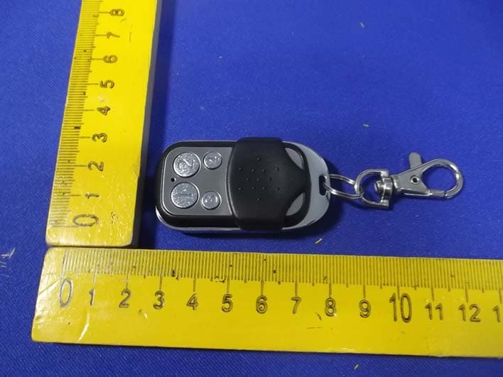
Click to zoom
Application Details
- Equipment Class
- DXX - Part 15 Low Power Communication Device Transmitter
- Date of Grant
- Sep 10, 2013
- Application Purpose
- Original Equipment
- Date of Application
- Sep 10, 2013
- Equipment Note
- ZME KFOB
- Frequency Range
- 908.40000000 - 908.40000000
- Company
- Z-Wave Europe GmbH
- Country
- Germany
Documents & Files
Document Text
Text extracted from the exhibit documents filed with the FCC. Open a document above to read the original.
Users Manual
1 Key Ring Controller KFOB2 Quick Start Please refer to the chapters below for detailed information about all aspects of the products usage. The device operates in normal control mode or in management mode. Pushing all four buttons for 5 sec. will turn the device into management mode (indicated by blinking green LED). The management mode will time out after 10 seconds if no further button is pushed. Button 3 confirms standard inclusion or exclusion started by a primary controller, button 2 issues a Node Information Frame or wakeup notification, button 4 is used to add devices into association groups and button 1 confirms inclusion or exclusion in NWI (network wide inclusion) mode. What is Z-Wave? This device is equipped with wireless communication complying with the Z-Wave standard. Z-Wave is the international standard for wireless communication in smart homes and buildings. It is using the frequency of 868.42 MHz (EU) or 908 MHz (US) to realize a very stable and secure communication between devices of different origin, type and brand. Each message is reconfirmed (two-way communication) and every mains powered node can act as a repeater for other nodes (meshed network) in case the receiver is not in direct wireless range of the transmitter. Z-Wave differentiates between Controllers and Slaves. Slaves are either sensors (S) trans- mitting metered or measured data or actuators (A) capable to execute an action. Controllers are either static mains powered controllers (C) also referred to as gateways or mobile battery operated remote controls (R). This results in a number of possible communication patterns within a Z-Wave network that are partly or completely supported by a specific device. 1. Controllers control actuators. 2. Actuators report change of status back to controller. 3. Sensors report change of status of measured values to controller. 4. Sensors directly control actuators. 5. Actuators control other actuators. 6. Remote controls send signals to static controllers to trigger scenes or other actions. 7. Remote controls control other actuators. Product description The Z-Wave.Me Key Fob is a Z-Wave device that can both control other Z-Wave devices and activate predefined scenes in an IP gateway. Although it is controlling other devices, the KFOB can’t act as Z-Wave network controller (primary or secondary) and will always need a Z-Wave network 2 controller to be included into a Z-Wave network. The device can be used in different modes that are selected by configuration parameters: 1. Control of groups of other Z-Wave devices using ‘ON’, ‘OFF’ and Dim commands. 2. Control of devices in proximity of the FOB using ‘ALL ON’ or ‘ALL OFF’ commands. 3. Control of a device in proximity of the FOB using ‘ON’ and ‘OFF’ commands. 4. Activation of predefined scenes in Gateways or other Z-Wave devices. Installation Guidelines The device comes ready to use with a battery already installed. On factory default the device is not included in any network and any button push will result in a long red blink indicating an error. This behavior can be used to test the factory default or exclusion state. For battery change, the device needs to be opened by removing the three little screws on the backside of the device. During reassembly, watch the position of the white rubber and make sure the silver buttons fit exactly into the nipples of the rubber. The device can be operated in two different modes: • Operation Mode: This is the mode where the device is controlling other Z-Wave devices or is activating scenes. • Management Mode: The device is turned into the management mode by pushing all four buttons for 5 sec. A blinking green LED indicates the management mode. In the management mode the buttons of the device have different functions. If no further action is performed the device will turn back to the normal mode after 10 sec. Any management action terminates the management mode as well. In management mode the following actions can be performed: • Button 1 - Network Wide Inclusion: The device can be included into a Z-Wave Network from any physical location in the network. This requires a primary controller supporting Explorer Frames. This mode lasts for 20 seconds and stops automatically. Any button press stops the mode as well. • Button 2 - Send Node Information Frame and Wake up Notification. (See explanation in the respective chapters below) • Button 3 – Standard Inclusion/Exclusion Mode: The device is included or excluded from a controller in direct wireless range. Any button press stops the mode. Performing an exclusion of the device from a network resets the device into its factory default. • Button 4 - Association Set: To assign target devices to one of the four association groups. Refer to the manuals section about association for more information how to set and unset association groups. Behavior within the Z-Wave network On factory default, the device does not belong to any Z-Wave network. The device needs to join an existing wireless network to communicate with the devices of this network. This process is called Inclusion. Devices can also leave a network. This process is called Exclusion. The primary controller of the Z-Wave network initiates both processes. This controller will be turned into exclusion respective inclusion mode. Please refer to your primary controllers manual on how to turn your controller into inclusion or exclusion mode. Only if the primary controller is in inclusion or exclusion mode, this device can join or leave the network. Leaving the network - i.e. being excluded - sets the device back to factory default. Z-Wave knows two types of inclusion processes: The standard inclusion requires that both controller and the device to be included are in physical proximity of few meters. The network wide inclusion allows including a device on every position in the network as long as there is at least one wireless connection to a device already included in the network. This function h…
Text truncated - open the document above for the full version.
Cover Letter(s)
Z-Wave Europe GmbH FCC Confidentiality Request Number: CF303 Version: V05 Date: 21-05-2012 (Permanent or also called long term confidentiality is the normal method to keep certain docuements confidential, and may apply to schematics, block diagrams, operational description and bill of materials.) To: Federal Communications Commission Equipment Authorization Branch 7435 Oakland Mills Road Columbia, MD 21046 Pursuant to 47 CFR Section 0.459(a) & (b), we, (the applicant / grantee) Company name Z-Wave Europe GmbH Address Goldbachstr. 13, City Hohenstein-Ernstthal Country Germany request for this certification filing under: Grantee Code Product Number FCC ID: 2A AYU-KFOBUS to maintain permanent confidentiality for the following documents submitted within this application: (please cross what is applicable, or add other documents, provide the file name and description) Exhibit File Name Description √ Operational Description Operational Description explaining the functioning of the block diagram √ Block Diagrams Block Diagrams showing the systematic building blocks of the EUT √ Schematics Diagrams Schematics showing components, their values and interconnection Bill of Materials List of components used on the PCB’s of the EUT Above materials crossed contain secrets, proprietary and technical information, which would customarily be guarded from competitors under 47 CFR, section 0.457(d)(2). Disclosure or publication or any portion of this company confidential material to other parties could cause substantial competitive harm and provide unjustified benefits for competitors. We understand that pursuant to 47 CFR section 0.457(d)(1)(ii) disclosure of the applicant and all accompanying documentation will not be made before the date of the grant. The documents indicated as confidential above, are not publicly available elsewhere. Attestation: City and Country: Date: Name: (this must be a person) Function:Signature: (or official company stamp) Hohenstein-Ernstthal, Germany 2013-09-05 Elke Geisle rCEO
External Photos
Figure 1 The EUT-Front View Figure 2 The EUT-Front View Figure 3 The EUT-Back View
ID Label/Location Info
Label Location On EUT
ID Label/Location Info
Product Name: ZME KFOB Model No.: ZNME KFOB US FCC ID: 2AAYU-KFOBUS
Internal Photos
Figure 4 The EUT-Inside View Figure 5 PCB of the EUT-Front View Figure 6 PCB of the EUT-Back View
Test Report
Shenzhen Anbotek Compliance Laboratory Limited FCC ID: 2AAYU-KFOBUS Page 1 of 19 Report No.: 201307850F Shenzhen Anbotek Compliance Laboratory Limited Tel: (86)755-26066544 Fax: (86)755-26014772 www.anbotek.com FCC TEST REPORT for Z-Wave Europe GmbH ZME KFOB Model No.: ZNME KFOB US Report Number : 201307850F Date of Test : Jul. 22~ Aug. 30, 2013 Date of Report : Sep. 05, 2013 Prepared for : Z-Wave Europe GmbH Address : Goldbachstr. 13, Hohenstein-Ernstthal, 09337 Germany Prepared By : Shenzhen Anbotek Compliance Laboratory Limited Address : 1/F., Building 1, SEC Industrial Park, No.0409 Qianhai Road, Nanshan District, Shenzhen, Guangdong, China Tel: (86) 755-26066544 Fax: (86) 755-26014772 Shenzhen Anbotek Compliance Laboratory Limited FCC ID: 2AAYU-KFOBUS Page 2 of 19 Report No.: 201307850F Shenzhen Anbotek Compliance Laboratory Limited Tel: (86)755-26066544 Fax: (86)755-26014772 www.anbotek.com TABLE OF CONTENTS Description Page Test Report 1. GENERAL INFORMATION ......................................................................................................... 4 1.1. Description of Device (EUT) ................................................................................................................... 4 1.2. Auxiliary Equipment Used during Test ................................................................................................... 5 1.3. Description of Test Facility ...................................................................................................................... 5 1.4. Measurement Uncertainty ........................................................................................................................ 5 2. TEST PROCEDURE ....................................................................................................................... 6 3. CONDUCTED LIMITS .................................................................................................................. 7 3.1. Block Diagram of Test Setup ................................................................................................................... 7 3.2. Power Line Conducted Emission Measurement Limits (15.207) ............................................................. 7 3.3. Configuration of EUT on Measurement ................................................................................................... 7 3.4. Operating Condition of EUT .................................................................................................................... 8 3.5. Test Procedure .......................................................................................................................................... 8 3.6. Power Line Conducted Emission Measurement Results .......................................................................... 8 4. RADIATION INTERFERENCE .................................................................................................... 9 4.1. Requirements (15.249, 15.209): ............................................................................................................... 9 4.2 Test Procedure ........................................................................................................................................... 9 4.3 Test Results ................................................................................................................................................ 9 5. OCCUPIED BANDWIDTH .......................................................................................................... 12 5.1. Requirements (15.249): .......................................................................................................................... 12 5.2. Test Procedure ........................................................................................................................................ 12 5.3. Test Configuration: ................................................................................................................................. 12 5.4. Test Results ............................................................................................................................................. 13 6. PHOTOGRAPH ............................................................................................................................. 15 6.1. Photo of Radiation Emission Test .......................................................................................................... 15 APPENDIX I (External Photos) (2 Pages) APPENDIX II (Internal Photos) (2 Pages) Shenzhen Anbotek Compliance Laboratory Limited FCC ID: 2AAYU-KFOBUS Page 3 of 19 Report No.: 201307850F Shenzhen Anbotek Compliance Laboratory Limited Tel: (86)755-26066544 Fax: (86)755-26014772 www.anbotek.com TEST REPORT Applicant : Z-Wave Europe GmbH Manufacturer : Z-Wave Europe GmbH EUT : ZME KFOB Model No. : ZNME KFOB US Serial No. : N/A Trade Mark : N/A Rating : DC 3V Battery Measurement Procedure Used: FCC Part15 Subpart C, Paragraph 15.207, 15.249 & 15.209 The device described above is tested by Shenzhen Anbotek Compliance Laboratory Limited to determine the maximum emission levels emanating from the device and the severe levels of the device can endure and its performance criterion. The measurement results are contained in this test report and Shenzhen Anbotek Compliance Laboratory Limited is assumed full of responsibility for the accuracy and completeness of these measurements. Also, this report shows that the EUT (Equipment Under Test) is technically compliant with the FCC Part 15 Subpart C requirements. This report applies to above tested sample only and shall not be reproduced in part without written approval of Shenzhen Anbotek Compliance Laboratory Limited. Date of Test : Jul. 22~ Aug. 30, 2013 Prepared by : (Tested Engineer / Rock Zeng ) Reviewer : (Project Manager / Sally Zhang ) Approved & Authorized Signer : (Manager / Tom Chen) Shenzhen Anbotek Compliance Laboratory Limited FCC ID: 2A…
Text truncated - open the document above for the full version.
Test Setup Photos
1. Photo of Radiated Emission Test
Contact Information
Applicant
Elke Geisler(CEO)
Technical Contact
Test Firm
Shenzhen Anbotek Compliance Laboratory LimitedDaniel zhu
[email protected]86-755-26014771
Technical Specifications
| # | Rule Parts | Frequency Range | Power Output |
|---|---|---|---|
| 1 | 15C | 908.4 MHz - 908.4 MHz | - |
Other Applications from Z-Wave Europe GmbH
2AAYU-ZMEURAZ
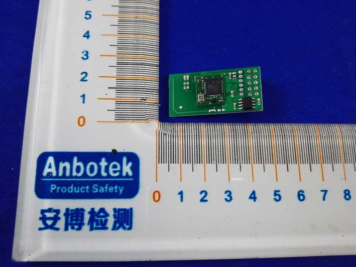
Dec 19, 2015Z-Wave Transceiver daughterboard
Equipment Class
DXX - Part 15 Low Power Communication Device Transmitter