2AAYU-ZMEURAZZ-Wave Transceiver daughterboard
Z-Wave Europe GmbH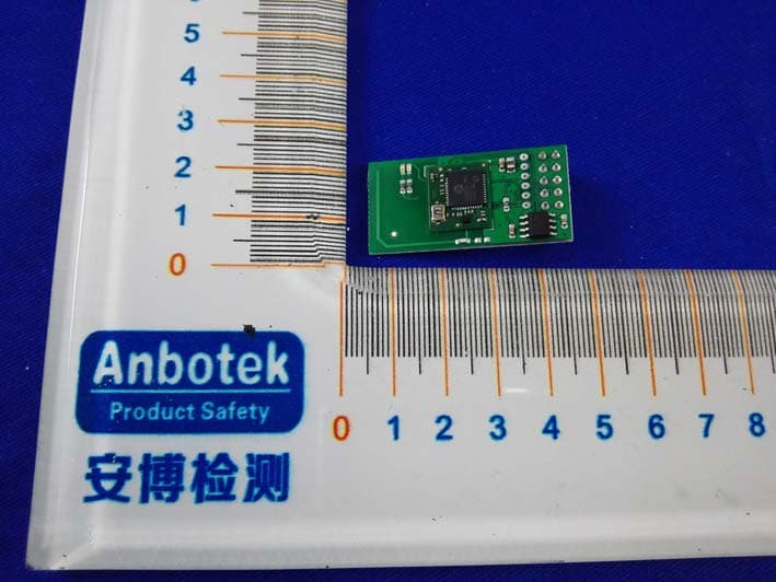
Click to zoom
Application Details
- Equipment Class
- DXX - Part 15 Low Power Communication Device Transmitter
- Date of Grant
- Dec 19, 2015
- Application Purpose
- Original Equipment
- Date of Application
- Dec 18, 2015
- Equipment Note
- Z-Wave Transceiver daughterboard
- Frequency Range
- 908.40000000 - 908.40000000
- Company
- Z-Wave Europe GmbH
- Country
- Germany
Documents & Files
Document Text
Text extracted from the exhibit documents filed with the FCC. Open a document above to read the original.
Users Manual
1 The RaZberry Smart Home Controller(user manual) Version2.1 Super Quick Start for Insiders 1.Create a SD card using the image from the link http://razberry.z-wave.me/z-way-server/razberry.img.zip 2.Go to find.zwave.me,find the IP address of your Pi,click on it 3.Setup your password and rememberyour RaZberryID for future remote access 4.Choosehttp://YOURPI _IP:8083or use find.zwave.me for remote accessto your Smart Home Interface. Quick Start for the rest of us RaZberry is a Z-Wave controller for your Smart Home.A built-in web server allows fast installation and usage without installing further software or apps.Of course there are apps for various mobile platforms that can be downloaded from the various app stores that further enhance the user experience of the solution. To use the RaZberry solution you need the following parts: -A Raspberry Pi microcomputer.If you don’t have it please refer to raspberry.org for sources to buy from -A SD Card with a minimum size of4GB -Power suppl yand Ethernet cable -The RaZberry add on module First prepare your SD Card.Download the complete image including Z-Wave control software and various other tools from the link given in the super quick start section.To prepare the SD Card please refer to the guidance on raspberry.org.Install the SD card into the Raspberry Pi and power it up. After about1minute open a web browser and point to find.zwave.me Below the login screen you will see the IP address of your RaZberry system.Click on the IP address link to open the configuration dialog. 2 The Configuration Service The configuration service is accessible with any web browser on Port8084.Whenever you want to change settings this service will be at your service and is available independent of the Z-Wave engine. 1.Find your RaZberry ID and remember it for remote access to your system. 2.Choose a password that will be used to authenticate for the remote access in the future. Whenever you access your RaZberry within your local network(as the first time)you will not need a password. The Configuration service uses the cloud infrastructure on find.zwave.me for the following functions: -Find the IP Addressof your RaZberry.You just used this function. -Remote Accesswhen you are outside your home.For this a valid password is required Ðsee above. -Firmware Update:Just click on the firmware update tab and follow the instructions -Remote Support:This function is usually disabled.You will need to enable it on request if you desire remote service.Allowing service people to access your RaZberry is100%under your control. Once you set your remote access password you are done with the initial configuration. Whenever you access find.zwave.me again and a local RaZberry is found clicking on the IP address will lead you right to your Smart Home User Interface.If your Pi uses a fixed IP address this address can be used for direct IP accesswithout using the find.zwave.me service.You can even turn off 3 the connection to the find.zwave.me service but be aware that you will not have any remote access capability anymore.Also in case the IP address of your RaZberry changes you may have difficulty to find the new address.Hence we recommend using find.zwave.me.Thesametimewe want you to have100 %controlof any cloud service usage of your system. Z-Wave Product Information This is a Z-Wave static controller.As a certified Z-Wave Plus device RaZberry communicating with all other Z- Wave certified devices regardless of vendor or year of origin and it implements the enhanced functions of Z-Wave Plus. This device can communicate in asecure environmentif the other device supports the secure environment too.If not the controller will fall back to the normal communication mode automatically.During inclusion the use of secure environment can be suppressed for performance reason if desired.In Z-Wave all non-battery powered device such as the RaZberry will act as routers for other devices to form a so-called meshed network. In case there is more than one controller in the network the controllers need to be kept synchronous in regard to their knowledge of the network.This is calledController Replicationand the following policy applies:(a)in case there is aSISin the network(check in Controller Info menu)every other controllers will query the SIS for updates.(b)In the rare case that there is no SIS and this device isPrimary Controllerplease re-include other controllers to perform a network information update. The device supports the command classesÕSwitchMultilevel’,ÕSwitchBinary’andÕBasic’to catch events from devices using these command classes to trigger actions in the controller.There is no other action performed than changing values in the device data objects. The device supports lifeline(association group1,max3nodes)and16channels(simulating a generic Multilevel Switch)to differentiate receiving commands from devices not able to send modern scene control commands.The channels support the same command classes(Basic ,SwitchBinary,SwitchMultilevel and Scene Activation)that do not perform any real action but allow command reception only. Various User Interfaces of RaZberry When going to http://YOURIP:8083you will see a selection menu to choose the web based UI you like to work with.ThetwomostinterestingUIsaretheZ-Wave Expert UI(to create and manage the Z-Wave Network)and theZ-Way Home Automationuser interface for day-by-day usage of the whole system.Above and beyond this you can use various mobile platform native apps you find in the app stores to access the system. 4 Just visit the Google App store or the iOS app store for native apps with the nameÔZ-Way”. The Z-Wave Expert UI The Z-Wave Expert User Interface isdesigned for installers,technically savvy peopleand other users that know how tobuilt and maintainaZ-Wavebased wireless network.Hence it uses some Z-Wave specific language and offers detailed insight into the work and data structure if the Z-Wave network.It allows to -Add(include)andremove(exclude)Z…
Text truncated - open the document above for the full version.
Users Manual
FCC information (additional) Radiation Exposure Statement: This equipment complies with FCC radiation exposure limits set forth for an uncontrolled environment. Co-location warning: This transmitter must not be co-located or operating in conjunction with any other antenna or transmitter. OEM integration instructions: This module has a LIMITED MODULAR APPROVAL, and is intended only for OEM integrators under the following conditions: As single, non-colocated transmitter, this module has no restrictions in relation to a safe distance from any user. The module shall be only used with the antenna(s) that have been originally tested and certified with this module. As long as these conditions above are met, further transmitter test will not be required. However, the OEM integrator is still responsible for testing their end-product for any additional compliance requirements required with this module installed (for example, digital device emissions, PC peripheral requirements, etc.). Validity of using the module certification: In the event that these conditions cannot be met, or when installing this module in another host as tested in this FCC filing, then the FCC authorization for this module in combination with the host equipment is no longer considered valid and the FCC ID of the module cannot be used on the final product. In these circumstances, the OEM integrator will be responsible for re-evaluating the end product (including the transmitter) and obtaining a separate FCC authorization. Custom design antennas may be used, however the OEM installer must following the FCC 15.21 requirements and verify if new FCC approval will be necessary. End product labeling: The final end product must be labeled in a visible area with the following: “Contains FCC ID: 2AAYU-ZMEURAZ”. Information that must be placed in the end user manual: The OEM integrator has to be aware not to provide information to the end user regarding how to install or remove this RF module in the user's manual of the end product which integrates this module. The end user manual shall include all required regulatory information/warning as show in this manual.
Users Manual
1 The RaZberry Smart Home Controller(user manual) Version2.1 Super Quick Start for Insiders 1.Create a SD card using the image from the link http://razberry.z-wave.me/z-way-server/razberry.img.zip 2.Go to find.zwave.me,find the IP address of your Pi,click on it 3.Setup your password and rememberyour RaZberryID for future remote access 4.Choosehttp://YOURPI _IP:8083or use find.zwave.me for remote accessto your Smart Home Interface. Quick Start for the rest of us RaZberry is a Z-Wave controller for your Smart Home.A built-in web server allows fast installation and usage without installing further software or apps.Of course there are apps for various mobile platforms that can be downloaded from the various app stores that further enhance the user experience of the solution. To use the RaZberry solution you need the following parts: -A Raspberry Pi microcomputer.If you don’t have it please refer to raspberry.org for sources to buy from -A SD Card with a minimum size of4GB -Power suppl yand Ethernet cable -The RaZberry add on module First prepare your SD Card.Download the complete image including Z-Wave control software and various other tools from the link given in the super quick start section.To prepare the SD Card please refer to the guidance on raspberry.org.Install the SD card into the Raspberry Pi and power it up. After about1minute open a web browser and point to find.zwave.me Below the login screen you will see the IP address of your RaZberry system.Click on the IP address link to open the configuration dialog. 2 The Configuration Service The configuration service is accessible with any web browser on Port8084.Whenever you want to change settings this service will be at your service and is available independent of the Z-Wave engine. 1.Find your RaZberry ID and remember it for remote access to your system. 2.Choose a password that will be used to authenticate for the remote access in the future. Whenever you access your RaZberry within your local network(as the first time)you will not need a password. The Configuration service uses the cloud infrastructure on find.zwave.me for the following functions: -Find the IP Addressof your RaZberry.You just used this function. -Remote Accesswhen you are outside your home.For this a valid password is required Ðsee above. -Firmware Update:Just click on the firmware update tab and follow the instructions -Remote Support:This function is usually disabled.You will need to enable it on request if you desire remote service.Allowing service people to access your RaZberry is100%under your control. Once you set your remote access password you are done with the initial configuration. Whenever you access find.zwave.me again and a local RaZberry is found clicking on the IP address will lead you right to your Smart Home User Interface.If your Pi uses a fixed IP address this address can be used for direct IP accesswithout using the find.zwave.me service.You can even turn off 3 the connection to the find.zwave.me service but be aware that you will not have any remote access capability anymore.Also in case the IP address of your RaZberry changes you may have difficulty to find the new address.Hence we recommend using find.zwave.me.Thesametimewe want you to have100 %controlof any cloud service usage of your system. Z-Wave Product Information This is a Z-Wave static controller.As a certified Z-Wave Plus device RaZberry communicating with all other Z- Wave certified devices regardless of vendor or year of origin and it implements the enhanced functions of Z-Wave Plus. This device can communicate in asecure environmentif the other device supports the secure environment too.If not the controller will fall back to the normal communication mode automatically.During inclusion the use of secure environment can be suppressed for performance reason if desired.In Z-Wave all non-battery powered device such as the RaZberry will act as routers for other devices to form a so-called meshed network. In case there is more than one controller in the network the controllers need to be kept synchronous in regard to their knowledge of the network.This is calledController Replicationand the following policy applies:(a)in case there is aSISin the network(check in Controller Info menu)every other controllers will query the SIS for updates.(b)In the rare case that there is no SIS and this device isPrimary Controllerplease re-include other controllers to perform a network information update. The device supports the command classesÕSwitchMultilevel’,ÕSwitchBinary’andÕBasic’to catch events from devices using these command classes to trigger actions in the controller.There is no other action performed than changing values in the device data objects. The device supports lifeline(association group1,max3nodes)and16channels(simulating a generic Multilevel Switch)to differentiate receiving commands from devices not able to send modern scene control commands.The channels support the same command classes(Basic ,SwitchBinary,SwitchMultilevel and Scene Activation)that do not perform any real action but allow command reception only. Various User Interfaces of RaZberry When going to http://YOURIP:8083you will see a selection menu to choose the web based UI you like to work with.ThetwomostinterestingUIsaretheZ-Wave Expert UI(to create and manage the Z-Wave Network)and theZ-Way Home Automationuser interface for day-by-day usage of the whole system.Above and beyond this you can use various mobile platform native apps you find in the app stores to access the system. 4 Just visit the Google App store or the iOS app store for native apps with the nameÔZ-Way”. The Z-Wave Expert UI The Z-Wave Expert User Interface isdesigned for installers,technically savvy peopleand other users that know how tobuilt and maintainaZ-Wavebased wireless network.Hence it uses some Z-Wave specific language and offers detailed insight into the work and data structure if the Z-Wave network.It allows to -Add(include)andremove(exclude)Z…
Text truncated - open the document above for the full version.
Users Manual
FCC information (additional) Radiation Exposure Statement: This equipment complies with FCC radiation exposure limits set forth for an uncontrolled environment. Co-location warning: This transmitter must not be co-located or operating in conjunction with any other antenna or transmitter. OEM integration instructions: This module has a LIMITED MODULAR APPROVAL, and is intended only for OEM integrators under the following conditions: As single, non-colocated transmitter, this module has no restrictions in relation to a safe distance from any user. The module shall be only used with the antenna(s) that have been originally tested and certified with this module. As long as these conditions above are met, further transmitter test will not be required. However, the OEM integrator is still responsible for testing their end-product for any additional compliance requirements required with this module installed (for example, digital device emissions, PC peripheral requirements, etc.). Validity of using the module certification: In the event that these conditions cannot be met, or when installing this module in another host as tested in this FCC filing, then the FCC authorization for this module in combination with the host equipment is no longer considered valid and the FCC ID of the module cannot be used on the final product. In these circumstances, the OEM integrator will be responsible for re-evaluating the end product (including the transmitter) and obtaining a separate FCC authorization. Custom design antennas may be used, however the OEM installer must following the FCC 15.21 requirements and verify if new FCC approval will be necessary. End product labeling: The final end product must be labeled in a visible area with the following: “Contains FCC ID: 2AAYU-ZMEURAZ”. Information that must be placed in the end user manual: The OEM integrator has to be aware not to provide information to the end user regarding how to install or remove this RF module in the user's manual of the end product which integrates this module. The end user manual shall include all required regulatory information/warning as show in this manual.
Cover Letter(s)
Z-Wave Europe GmbHFCC Confidentiality Request Number:CF303 Version:V05 Date: 21-05-2012 (Permanent or also called long term confidentiality is the normal method to keep certain docuements confidential, and may apply to schematics, block diagrams, operational description and bill of materials.) To: Federal Communications Commission Equipment Authorization Branch 7435 Oakland Mills Road Columbia, MD 21046 Pursuant to 47 CFR Section 0.459(a) & (b), we, (the applicant / grantee) Company nameZ-Wave Europe GmbH AddressAntonstr. 3, CityHohenstein-Ernstthal, 09337 CountryGermany request for this certification filing under: Grantee CodeProduct Number FCC ID:2AAYU-ZMEURAZ to maintainpermanent confidentialityfor the following documents submitted within this application: (please cross what is applicable, or add other documents, provide the file name and description) ExhibitFile NameDescription √ Operational DescriptionOperational Descriptionexplaining the functioning of the block diagram √ Block DiagramsBlock Diagramsshowing the systematic building blocks of the EUT √ Schematics DiagramsSchematicsshowing components, their values and interconnection Bill of MaterialsList of components used on the PCB’s of the EUT Above materials crossed contain secrets, proprietary and technical information, which would customarily be guarded from competitors under 47 CFR, section 0.457(d)(2). Disclosure or publication or any portion of this company confidential material to other parties could cause substantial competitive harm and provide unjustified benefits for competitors. We understand that pursuant to 47 CFR section 0.457(d)(1)(ii) disclosure of the applicant and all accompanying documentation will not be made before the date of the grant. The documents indicated as confidential above, are not publicly available elsewhere. Attestation: City and Country:Date:Name: (this must be a person) Function:Signature: (or official company stamp) Hohenstein-Ernstthal, Germany 2015-12-05 Elke GeislerCEO
Cover Letter(s)
Filed under 15.249, so RF exposure not applicable
Cover Letter(s)
Z-Wave Europe GmbHFCC Confidentiality Request Number:CF303 Version:V05 Date: 21-05-2012 (Permanent or also called long term confidentiality is the normal method to keep certain docuements confidential, and may apply to schematics, block diagrams, operational description and bill of materials.) To: Federal Communications Commission Equipment Authorization Branch 7435 Oakland Mills Road Columbia, MD 21046 Pursuant to 47 CFR Section 0.459(a) & (b), we, (the applicant / grantee) Company nameZ-Wave Europe GmbH AddressAntonstr. 3, CityHohenstein-Ernstthal, 09337 CountryGermany request for this certification filing under: Grantee CodeProduct Number FCC ID:2AAYU-ZMEURAZ to maintainpermanent confidentialityfor the following documents submitted within this application: (please cross what is applicable, or add other documents, provide the file name and description) ExhibitFile NameDescription √ Operational DescriptionOperational Descriptionexplaining the functioning of the block diagram √ Block DiagramsBlock Diagramsshowing the systematic building blocks of the EUT √ Schematics DiagramsSchematicsshowing components, their values and interconnection Bill of MaterialsList of components used on the PCB’s of the EUT Above materials crossed contain secrets, proprietary and technical information, which would customarily be guarded from competitors under 47 CFR, section 0.457(d)(2). Disclosure or publication or any portion of this company confidential material to other parties could cause substantial competitive harm and provide unjustified benefits for competitors. We understand that pursuant to 47 CFR section 0.457(d)(1)(ii) disclosure of the applicant and all accompanying documentation will not be made before the date of the grant. The documents indicated as confidential above, are not publicly available elsewhere. Attestation: City and Country:Date:Name: (this must be a person) Function:Signature: (or official company stamp) Hohenstein-Ernstthal, Germany 2015-12-05 Elke GeislerCEO
Cover Letter(s)
Filed under 15.249, so RF exposure not applicable
External Photos
Figure 1 The Host-Overall View Figure 2 The Host-Front View Figure 3 The Host-Back View Figure 4 The Host-Inside View EUT Figure 5 The EUT-Front View Figure 6 The EUT-Back View Antenna
External Photos
Figure 1 The Host-Overall View Figure 2 The Host-Front View Figure 3 The Host-Back View Figure 4 The Host-Inside View EUT Figure 5 The EUT-Front View Figure 6 The EUT-Back View Antenna
ID Label/Location Info
Product Name:Z-Wave Transceiver daughterboard Model No.:ZMEURAZ FCC ID:2AAYU-ZMEURAZ
ID Label/Location Info
Label Location On EUT
ID Label/Location Info
Product Name:Z-Wave Transceiver daughterboard Model No.:ZMEURAZ FCC ID:2AAYU-ZMEURAZ
ID Label/Location Info
Label Location On EUT
Internal Photos
Figure 7 The EUT-Inside View Figure 8 PCB of the EUT-Front View Figure 9 PCB of the EUT-Back View Figure 10 PCB of the EUT-Front View Figure 11 PCB of the EUT-Back View
Internal Photos
Figure 7 The EUT-Inside View Figure 8 PCB of the EUT-Front View Figure 9 PCB of the EUT-Back View Figure 10 PCB of the EUT-Front View Figure 11 PCB of the EUT-Back View
Test Report
Shenzhen Anbotek Compliance Laboratory Limited FCC ID: 2AAYU-ZMEURAZ Page 1 of 29 Report No.: R011510092I Shenzhen Anbotek Compliance Laboratory Limited Tel:(86)755-26066544 Fax:(86)755-26014772 www.anbotek.com FCC TEST REPORT for Z-Wave Europe GmbH Z-Wave Transceiver daughterboard Model No.: ZMEURAZ Report Number:R011510092I Date of Test:Oct. 14~ Nov. 30, 2015 Date of Report:Dec. 01, 2015 Preparedfor:Z-Wave Europe GmbH Address:Antonstr. 3, Hohenstein-Ernstthal, 09337, Germany PreparedBy:Shenzhen Anbotek Compliance LaboratoryLimited Address:1/F., Building 1, SEC Industrial Park, No.0409 Qianhai Road, Nanshan District, Shenzhen, Guangdong, China Tel: (86) 755-26066544 Fax: (86) 755-26014772 Shenzhen Anbotek Compliance Laboratory Limited FCC ID: 2AAYU-ZMEURAZ Page 2 of 29 Report No.: R011510092I Shenzhen Anbotek Compliance Laboratory Limited Tel:(86)755-26066544 Fax:(86)755-26014772 www.anbotek.com TABLE OF CONTENTS Description Page Test Report 1. GENERAL INFORMATION ...................................................................................................... 4 1.1. Description of Device (EUT) ................................................................................................................ 4 1.2. Auxiliary Equipment Used during Test ................................................................................................ 5 1.3. Description of Test Facility .................................................................................................................. 5 1.4. Measurement Uncertainty ..................................................................................................................... 5 2. TEST PROCEDURE .................................................................................................................... 6 3. Conducted Emission Test ............................................................................................................. 7 3.1. Block Diagram of Test Setup ................................................................................................................ 7 3.2. Power Line Conducted Emission Measurement Limits (15.207) ......................................................... 7 3.3. Configuration of EUT on Measurement ............................................................................................... 7 3.4. Operating Condition of EUT ................................................................................................................ 7 3.5. Test Procedure ...................................................................................................................................... 8 3.6. Test equipment ...................................................................................................................................... 8 3.7. Power Line Conducted Emission Measurement Results ...................................................................... 8 4. RADIATION INTERFERENCE .............................................................................................. 13 4.1. Requirements (15.249, 15.209): .......................................................................................................... 13 4.2. Test Procedure .................................................................................................................................... 13 4.3. Test Results ......................................................................................................................................... 14 5. OCCUPIED BANDWIDTH ...................................................................................................... 18 5.1. Requirements (15.249): ....................................................................................................................... 18 5.2. Test Procedure .................................................................................................................................... 18 5.3. Test Configuration: ............................................................................................................................. 19 5.4. Test Results ......................................................................................................................................... 19 6. ANTENNA APPLICATION ..................................................................................................... 21 6.1. Antenna requirement ........................................................................................................................... 21 6.2. Result .................................................................................................................................................. 21 7. PHOTOGRAPH ......................................................................................................................... 22 7.1. Photo of Conducted Emission Measurement ...................................................................................... 22 7.2. Photo of Radiated Emission Test ........................................................................................................ 22 APPENDIX I (EXTERNAL PHOTOS) ....................................................................................... 24 APPENDIX II(INTERNAL PHOTOS) ........................................................................................ 27 Shenzhen Anbotek Compliance Laboratory Limited FCC ID: 2AAYU-ZMEURAZ Page 3 of 29 Report No.: R011510092I Shenzhen Anbotek Compliance Laboratory Limited Tel:(86)755-26066544 Fax:(86)755-26014772 www.anbotek.com TEST REPORT Applicant: Z-Wave Europe GmbH Manufacturer: Airline Mechanical Company Ltd. EUT: Z-Wave Transceiver daughterboard Model No.: ZMEURAZ Serial No.: N/A Trade Mark: N/A Rating: DC 3.3V, 35mA Measurement Procedure Used: FCC Part15 Subpart C, Paragraph 15.207, 15.249 & 15.209 The device described above is tested by Shenzhen Anbotek Compliance Laboratory Limited to determine the maximum emission l…
Text truncated - open the document above for the full version.
Test Setup Photos
1. Photo of Conducted Emission Measurement 2. Photo of Radiated Emission Test
Test Setup Photos
1. Photo of Conducted Emission Measurement 2. Photo of Radiated Emission Test
Contact Information
Applicant
Elke Geisler(CEO)
Technical Contact
Test Firm
Shenzhen Anbotek Compliance Laboratory LimitedDaniel zhu
[email protected]86-755-26014771
Technical Specifications
| # | Rule Parts | Frequency Range | Power Output |
|---|---|---|---|
| 1 | 15C | 908.4 MHz - 908.4 MHz | - |
Other Applications from Z-Wave Europe GmbH
2AAYU-KFOBUS
Sep 10, 2013ZME KFOB
Equipment Class
DXX - Part 15 Low Power Communication Device Transmitter