2AAZG3026A1Marker DAM
DYE PRECISION, INC.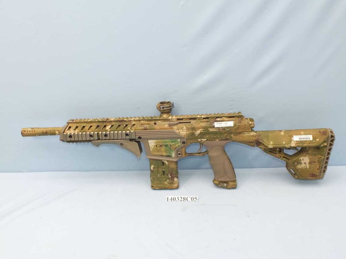
Click to zoom
Application Details
- Equipment Class
- DXX - Part 15 Low Power Communication Device Transmitter
- Date of Grant
- May 22, 2014
- Application Purpose
- Original Equipment
- Date of Application
- May 22, 2014
- Equipment Note
- Marker DAM
- Frequency Range
- 2408.00000000 - 2474.00000000
- Company
- DYE PRECISION, INC.
- Country
- United States
Documents & Files
Document Text
Text extracted from the exhibit documents filed with the FCC. Open a document above to read the original.
Users Manual
WWW.DYEPAINTBALL.COM DAM™ OWNER’S MANUAL WWW.DYEPAINTBALL.COM 1 WWW.DYEPAINTBALL.COM 2 WARNING IMPORTANT SAFETY INSTRUCTIONS AND GUIDELINES WWW.DYEPAINTBALL.COM 3 WARNING IMPORTANT SAFETY INSTRUCTIONS AND GUIDELINES WWW.DYEPAINTBALL.COM 4 2 1 3 WWW.DYEPAINTBALL.COM 5 7 6 4 5 WWW.DYEPAINTBALL.COM 6 WARNING: AFTER STEP 5, THE DAM™ WILL BE LIVE. BEFORE PROCEEDING, MAKE SURE THE BARREL SOCK IS IN PLACE AND DO NOT POINT THE DAM™ AT ANYTHING YOU DON’T INTEND TO SHOOT. 7 WWW.DYEPAINTBALL.COM 8 1 2 3 WWW.DYEPAINTBALL.COM When servicing your marker:• Make sure a barrel sock is fitted to the DAM™.• Make sure your loader/magazine is removed from the DAM™.• Make sure there are no paintballs in the breech of the DAM™.• Always remove the first stage regulator and relieve all residual gas pressure from the DAM™ before disassembly.• The DAM™ can hold a small residual charge of gas, typically 2 shots, with the first stage regulator removed. Always discharge the marker in a safe direction to relieve this residual gas pressure. WWW.DYEPAINTBALL.COM 10 FACTORY MODE CUSTOM MODE (DEFAULT) WWW.DYEPAINTBALL.COM 11 CONFIGURABLE MODE BLOCKED CONFIGURATION MODE 3 WWW.DYEPAINTBALL.COM 12 WWW.DYEPAINTBALL.COM 13 WWW.DYEPAINTBALL.COM 14 • Be sure the trigger is not adjusted to the point where it is too sensitive and may cause accidental discharge of the marker.• Removing the trigger spring will cause premature wear on the microswitch, resulting in failure. 2 1 WWW.DYEPAINTBALL.COM 15 3
Users Manual
WWW.DYEPAINTBALL.COM 16 WWW.DYEPAINTBALL.COM 17 When servicing your marker:• Make sure your loader and magazine are removed from the marker.• Make sure there are no paintballs in the breech of the marker.• Always remove the air supply and relieve all gas pressure in the marker before disassembly.• When using the marker in temperatures below 50° Fahrenheit it may be necessary to lube the DAM™ bolt more frequently. WWW.DYEPAINTBALL.COM 18 #020 #017 #012 #009 #011 #007 #010 Bolt Bumper Front #13x2 #015 #014 #013 #019 WWW.DYEPAINTBALL.COM 19 1 020 N 70 2 019 N 70 3 017 N 70 4 015 N 70 5 014 N 70 6 013 N 70 7 012 N 70 8 010 N 70 9 009 N 90 10 007 UR 90 11 013x2mm N 90 12 Bolt Bumper Front N 90 DAM™ BOLT O-RING LIST 12 5 4 11 1 6 1 1 1 1 9 3 5 10 2 7 8 WWW.DYEPAINTBALL.COM 20 WWW.DYEPAINTBALL.COM 21 010 BN 70 020 BN 70 PISTON BODY TOOL-LESS BACK CAP REGULATOR SEAT C-CLIP SHIM STACK CORRECT ORIENTATION )()()()() 1 WWW.DYEPAINTBALL.COM 22 WARNING: Loaded magazines will eject paintballs as soon as the cover door opens. Do NOT open Cover Door while magazine is pointed at your face or anyone else’s face! For safety, always place you hand over the top of a magazine before opening Cover Door. 1 WWW.DYEPAINTBALL.COM 23 WARNING - DO NOT depress bumper without paintballs in the DTM. In rare occasions releasing a locked bumper without paintballs in place can seriously damage the DTM. NEVER discharge a fully locked bumper at yourself or anyone else. 5 2 3 4 WWW.DYEPAINTBALL.COM 24 WARNING: After the following step, the DAM™ will be live and fire a paintball at the next trigger pull. Keep your DAM™ pointed away from anything you DO NOT want to shoot! WWW.DYEPAINTBALL.COM 25 6 7 8 9 WWW.DYEPAINTBALL.COM 26 WWW.DYEPAINTBALL.COM 27 1 WWW.DYEPAINTBALL.COM 29 WWW.DYEPAINTBALL.COM 30 1 2 3 WWW.DYEPAINTBALL.COM WWW.DYEPAINTBALL.COM 32 WWW.DYEPAINTBALL.COM 33 WWW.DYEPAINTBALL.COM WWW.DYEPAINTBALL.COM WWW.DYEPAINTBALL.COM 36 1 3 8 7 14 13 11 15 10 6 12 9 2 5 4 WWW.DYEPAINTBALL.COM 37 1 DAM Bolt2 Hopper Feed Cover3 Barrel Thread Carrier4 Eye Pipe Sytem5 On the Fly System6 Hyper™ In-Line Reg7 DTM Reciever Well8 Solenoid9 Spring Tension Adjust10 DAM Ultralite Frame11 Air Through Frame12 DAM™ Body13 DTM14 Modular Shroud15 ISStock PARTS LIST DYE Precision, Inc.10637 Scripps Summit Ct.San Diego, CA. 92131 DYE EuropeDye House, 7-8 Commerce WayCroydon, Surrey United Kingdom CR0 4XA DYE Germany GmbHAlbert Einstein Str. 2 B 77656 OffenburgGermany DYE AsiaNo. 253, Guojhong Rd. Dali City, Taichung County 412 Taiwan (R.O.C.)
External Photos
Page 1 CONSTRUCTION PHOTOS OF EUT
Internal Photos
Page 2 Page 3 Page 4 Page 5 Page 6 Page 7
Operational Description
FCC ID: 2AAZG3026A1 Report No.: RF140328C05 Operational Description This device is a Marker DAM. The transmitter of the EUT is powered by 9Vdc from battery. The antenna is PCB antenna without antenna connector. For more detailed instruction, please take a look at the user’s manual.
Test Report
Report No.: RF140328C05 1 of 21 Report Format Version 5.0.0 FCC TEST REPORT REPORT NO.: RF140328C05 MODEL NO.: 3026YYYY (Y= 0-9, A-Z or blank) FCC ID: 2AAZG3026A1 RECEIVED: Mar. 28, 2014 TESTED: May 08, 2014 ISSUED: May 14, 2014 APPLICANT: DYE PRECISION, INC. ADDRESS: 10637 Scripps Summit Court San Diego, CA 92131 ISSUED BY: Bureau Veritas Consumer Products Services (H.K.) Ltd., Taoyuan Branch LAB ADDRESS: No. 47, 14th Ling, Chia Pau Vil., Lin Kou Dist., New Taipei City, Taiwan, R.O.C. TEST LOCATION: No. 19, Hwa Ya 2nd Rd, Wen Hwa Tsuen, Kwei Shan Hsiang, Taoyuan Hsien 333, Taiwan, R.O.C. This report is for your exclusive use. Any copying or replication of this report to or for any other person or entity, or use of our name or trademark, is permitted only with our prior written permission. This report sets forth our findings solely with respect to the test samples identified herein. The results set forth in this report are not indicative or representative of the quality or characteristics of the lot from which a test sample was taken or any similar or identical product unless specifically and expressly noted. Our report includes all of the tests requested by you and the results thereof based upon the information that you provided to us. You have 60 days from date of issuance of this report to notify us of any material error or omission caused by our negligence, provided, however, that such notice shall be in writing and shall specifically address the issue you wish to raise. A failure to raise such issue within the prescribed time shall constitute your unqualified acceptance of the completeness of this report, the tests conducted and the correctness of the report contents. Unless specific mention, the uncertainty of measurement has been explicitly taken into account to declare the com pliance or non-compliance to the specification. This report should not be used by the client to claim product certification, approval, or endorsement by TAF or any government agencies. Report No.: RF140328C05 2 of 21 Report Format Version 5.0.0 Table of Contents RELEASE CONTROL RECORD .............................................................................................................. 3 1. CERTIFICATION ......................................................................................................................... 4 2. SUMMARY OF TEST RESULTS ................................................................................................. 5 2.1 MEASUREMENT UNCERTAINTY .............................................................................................. 5 3. GENERAL INFORMATION ......................................................................................................... 6 3.1 GENERAL DESCRIPTION OF EUT ............................................................................................ 6 3.2 DESCRIPTION OF TEST MODES .............................................................................................. 7 3.2.1 TEST MODE APPLICABILITY AND TESTED CHANNEL DETAIL ............................................. 8 3.3 DESCRIPTION OF SUPPORT UNITS ........................................................................................ 9 3.3.1 CONFIGURATION OF SYSTEM UNDER TEST ......................................................................... 9 3.4 GENERAL DESCRIPTION OF APPLIED STANDARDS ............................................................. 9 4. TEST TYPES AND RESULTS ................................................................................................... 10 4.1 RADIATED EMISSION and band edge MEASUREMENT ........................................................ 10 4.1.1 LIMITS OF RADIATED EMISSION AND BAND EDGE MEASUREMENT ............................... 10 4.1.2 TEST INSTRUMENTS ............................................................................................................... 11 4.1.3 TEST PROCEDURES ............................................................................................................... 12 4.1.4 DEVIATION FROM TEST STANDARD ..................................................................................... 12 4.1.5 TEST SETUP ............................................................................................................................ 13 4.1.6 EUT OPERATING CONDITIONS .............................................................................................. 13 4.1.7 TEST RESULTS ........................................................................................................................ 14 5. PHOTOGRAPHS OF THE TEST CONFIGURATION ............................................................... 19 6. INFORMATION ON THE TESTING LABORATORIES .............................................................. 20 7. APPENDIX A – MODIFICATION RECORDERS FOR ENGINEERING CHANGES TO THE EUT BY THE LAB ...................................................................................................................... 21 Report No.: RF140328C05 3 of 21 Report Format Version 5.0.0 RELEASE CONTROL RECORD ISSUE NO. REASON FOR CHANGE DATE ISSUED RF140328C05 Original release. May 14, 2014 Report No.: RF140328C05 4 of 21 Report Format Version 5.0.0 1. CERTIFICATION PRODUCT: Marker DAM MODEL NO.: 3026YYYY (Y= 0-9, A-Z or blank) BRAND: DYE APPLICANT: DYE PRECISION, INC. TESTED: May 08, 2014 TEST SAMPLE: ENGINEERING SAMPLE STANDARDS: FCC Part 15, Subpart C (Section 15.249) ANSI C63.10-2009 The above equipment (model: 3026) has been tested by Bureau Veritas Consumer Products Services (H.K.) Ltd., Taoyuan Branch, and found compliance with the requirement of the above standards. The test record, data evaluation & Equipment Under Test (EUT) configurations represented herein are true and accurate accounts of the measurements of the sample’s EMC characteristics under the conditions specified in this report. PREPARED BY : , DATE : May 14, 2014 Suntee Liu / Specialist APPROVED BY : , DATE : May 14, 20…
Text truncated - open the document above for the full version.
Test Setup Photos
1 PHOTOGRAPHS OF THE TEST CONFIGURATION RADIATED EMISSION TEST
Contact Information
Applicant
Billy Wing(R&D Engineer)
Test Firm
Bureau Veritas CPS (H.K.) Ltd., Taoyuan BranchRichard Chen
Technical Specifications
| # | Rule Parts | Frequency Range | Power Output |
|---|---|---|---|
| 1 | 15C | 2.41 GHz - 2.47 GHz | - |
Other Applications from DYE PRECISION, INC.
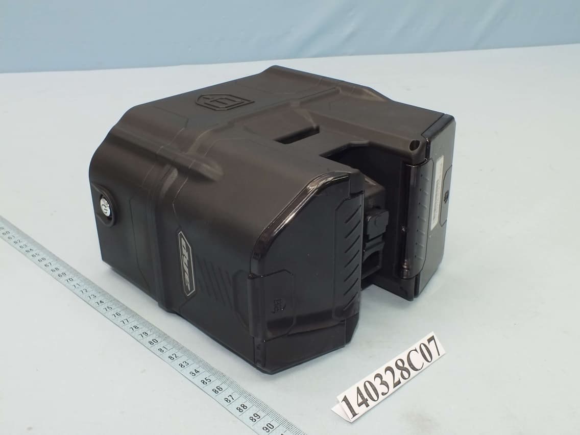
2AAZG5005A1
May 22, 2014Box Rotor
Equipment Class
DXX - Part 15 Low Power Communication Device Transmitter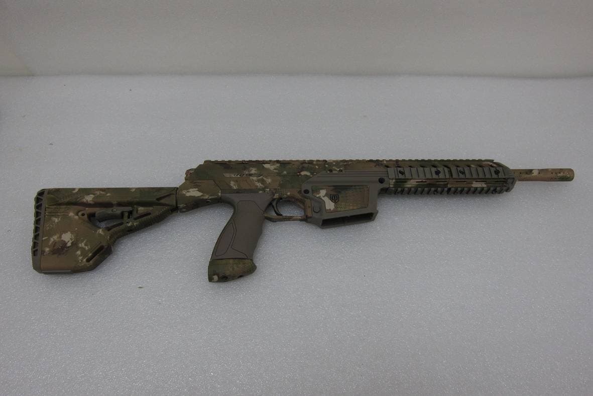
2AAZG3026
Oct 28, 2013Marker DAM
Equipment Class
DXX - Part 15 Low Power Communication Device Transmitter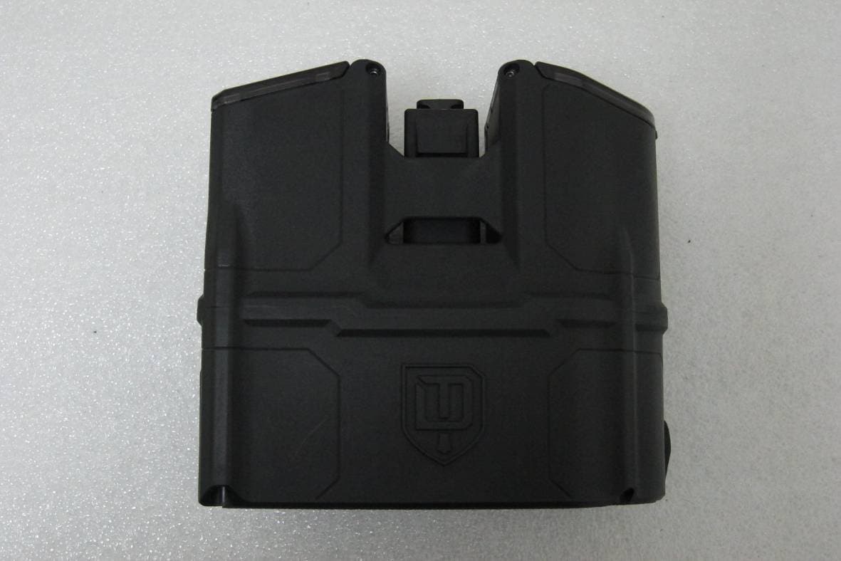
2AAZG5005
Oct 28, 2013Box Rotor
Equipment Class
DXX - Part 15 Low Power Communication Device Transmitter