2AAZPFAN52R-M60REMOTE CONTROL
Carewell Electric Technology (Zhongshan) Co., Ltd.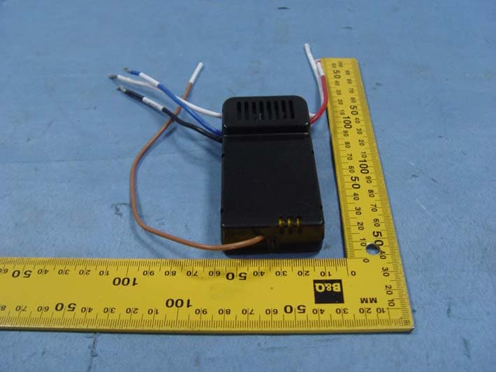
Click to zoom
Application Details
- Equipment Class
- CYY - Communications Receiver used w/Pt 15 Transmitter
- Date of Grant
- Jul 12, 2015
- Application Purpose
- Original Equipment
- Date of Application
- Jul 11, 2015
- Equipment Note
- REMOTE CONTROL
- Frequency Range
- 315.00000000 - 315.00000000
- Country
- China
Documents & Files
Document Text
Text extracted from the exhibit documents filed with the FCC. Open a document above to read the original.
Users Manual
Remote controller GENERAL INFORMATION This remote controller is designed to separately control your ceiling fan speed and light brightness. There are four buttons (HI, MED, LOW, OFF) to control the speed of the fan and off. The light dimmer button will control the light brightness dimmer and off. The red indicator on the transmitter will light when one of the five buttons is pressed. INSTRUCTION OF INSTALLATION AND OPERATION 1.SETTING THE CODES This unit has 16 different code combinations. To set the codes, perform the following steps: A. Setting the codes on the transmitter: a. Remove battery cover. Press firmly on the arrow and slide battery cover off. b. Slide code switches to your choice of up or down position. (Factory setting is all up. Do not use this position. Use a Small screwdriver or ball point pen to slide firmly up or down (Figure 1)). B. Setting the codes on the receiver: The Learn Key must be pressed within 30 seconds, after pressing the Power button. If not, please press the Power button to restart. Keep pressing the button learn key in excess of 3 second it becomes a LEARN status. The receiver can remember the last codes status .The light flash two times. 2.INSTALLING RECEIVER IN CEILING FAN A. Safety precautions: WARNING: HIGH VOLTAGE! Disconnect power by removing fuse or switching off circuit breaker. Do not use with other solid state fans. Electrical wire must meet all local and national electrical code requirements. Supply for fan must be 110/120 volt, 60Hz. Maximum fan motor amps: 1.0, Maximum down light watts: 60 LED. Otherwise power can cause serious injury or death. B. Installing receiver in fan: a. Remove power from the circuit. b. Remove ceiling fan canopy from the mounting bracket. c. Disconnect existing wiring between ceiling fan and Supply in electrical junction box. d. Make connections as follows, using the wire nuts Maximum up light watts: 100 incandescent and ballast. CONNECT TO Green fan wire ....Bare supply wire Black receiver wire(AC IN L) .... Black supply wire White receiver wire(AC IN N) ....White supply wire White receiver wire(TO MOTOR N) ....White fan wire Black receiver wire(TO MOTOR L) ....Black fan wire Blue receiver wire(DOWN LIGHT) ....Blue light wire PJES1002 CANOPY (FIG.2) LIGHT MUST KEEP AT THE TURN ON FAN MUST KEEP AT THE HIGH SPEED Use wire connecting nuts supplied with the fan FROM POWER SOURCE AC 110~120 VOLT 60Hz 3.5AMPS. Use wire connecting nuts supplied with the remote controller. WIRE NUT (FIG.3) WHITE A C L A C N INPUT OUTPUT RED BLUE ANT CANOPY BLUE B L AC K WHITE WHITE B L ACK R ECE IV E R Model FAN52R-M60 ACN ACL ANT COM FAN LIGHT TRANSMITTER CODE SWITCHES (FIG.1) (FIG.2) SWITCHES CODE ON 2 3 4 1 O N INPUT OUTPUT RECEIVER If other fans or supply wires are different colour, have this unit installed by qualified licensed electrician. e. Push all connected wires up into junction box. f. Lay the brown antenna wire on top of the receiver, and put the receiver into the mounting bracket. g. Reinstall the canopy on the mounting bracket. h. Restore power. 3. OPERATING TRANSMITTER: A. Install 12 volt battery. (To prevent damage to transmitter, remove the battery if not use for a long time). B. Store the transmitter away from excessive heat or humidity. C. This remote control unit is equipped with 16 code combinations. To prevent possible interference from or to other remote units such as garage door openers, car alarm or security system. If you find that your fan and light kit go on And off without using your remote control, simply change the code combination in your transmitter and receiver. D. Operating the buttons on the panel of the transmitter. HI key -for fan high speed. MED key-for fan medium speed. LOW key-for fan low speed. OFF key-for fan speed off. FAN REV key-for fan reverse . The light function is controlled by pressing the LIGHT key down to increase or decrease light. Tap key quickly to turn light off or on. Keep pressing the button in excess of 0.7 second it becomes a dimmer, the light varies cyclically in 0.8 second. The receiver can remember the last status of the light brightness when the light was switched, so that it can resume to adjust the light brightness. YOUR REMOTE NOW HAS FULL CONTROL OF THE FAN AND LIGHT. OPERATION DISTANCE 20 FEET TRANSMITTER MODEL: FAN-35T2 Optional Wall Mounting for Transmitter Holder Place in accessible area of your home, and screw the transmitter holder into wall using the two screws provided, slide hand unit into holder. 4. TROUBLE SHOOTING GUIDE 1. Fails to operate a. Power to receiver ? b. Receiver wired correctly ? c. Fan manual speed control in highest position ? d. Light kit switch turned on ? e. Good battery in the transmitter ? f. Code set at exact same positions in both transmitter and receiver ? 2. Wont operate at distance If transmitter operates fan/light kit when the up close, but not at 20 feet away. Try placing the brown antenna wire higher, up through ceiling/outside the junction box. ' NOTICE ! Your ceiling fan and light kit assembly must meet the following requirements: 1. Do not use with other solid state fans. 2. Electrical rating: 120v 60Hz 3.5A MAX. Motor amps: 1.0 MAX. Down Light watts: 60-(LED) WARNING TO REDUCE THE RISK OF SHOCK, THIS FAN MUST BE INSTALLED WITH A WALL CONTROL/SWITCH. NOTE: THE MANUFACTURER IS NOT RESPONSIBLE FOR ANY RADIO OR TV INTERFERENCE CAUSED BY UNAUTHORIZED MODIFICATIONS TO THIS EQUIPMENT. SUCH MODIFICATIONS COULD VOID THE USER'S AUTHORITY TO OPERATE THE EQUIPMENT. PJES1002 2 3 A 1 2 V FCC ID: L3HFAN35T2 FCC Statement: 1.This device complies with Part 15 of the FCC Rules. Operation is subject to the following two conditions: (1)This device may not cause harmful interference. (2)This device must accept any interference received, including interference that may cause undesired operation. 2. Changes or modifications not expressly approved by the party responsible for compliance could void the user's authority to operate the equipment.
Cover Letter(s)
SCS-F18: Project and Product Certification Representative Authorization Letter Page 1 of 2 Rev 5.0 775 Montague Expressway Milpitas, CA 95035 Tel: 408-526-1188 Fax: 408-526-1088 Email: [email protected] Project and Product Certification Representative Authorization Letter Revision History Reason for Amendment (current / obsolete) From To Approved Date Initial Release (obsolete) 1.0 1.0 Nov-14-2006 Revised wording (obsolete) 1.0 2.0 Sept–25-2007 Updated company template (obsolete) 2.0 3.0 Jan-31-2012 Updated letter information (obsolete) 3.0 4.0 May-23-2014 Added FCC ID field (current) 4.0 5.0 Sept 16 2014 SCS-F18: Project and Product Certification Representative Authorization Letter Page 2 of 2 Rev 5.0 Carewell Electric Technology (Zhongshan) Co., Ltd. 2015-07-07 To: SIEMIC, INC. 775 Montague Expressway, Milpitas, CA 95035 USA Dear Sir/Madam, Re: Product Certification Representative Authorization Letter We, Carewell Electric Technology (Zhongshan) Co., Ltd. hereby authorize SIEMIC, Inc. to act as a Certification Body for certifying for the following project(s): Product Description: REMOTE CONTROL Model name: FAN52R-M60 FCC ID: 2AAZPFAN52R-M60 Sincerely, Client’s signature : Allen XU Client’s name / title:Manager Contact information / address :+86-760-88582800 (Torch Development Zone, No.2, Ouya Road, Zhongshan, Guangdong,China )
Cover Letter(s)
SCS-F19: Confidentiality Request Letter Page 1 of 2 Rev 4.0 775 Montague Expressway Milpitas, CA 95035 Tel: 408-526-1188 Fax: 408-526-1088 Email: [email protected] Confidentiality Request Letter Revision History Reason for Amendment (current / obsolete) From To Approved Date Initial Release (obsolete) 1.0 1.0 Nov-14-2006 Adding CFR 2.459 (obsolete) 1.0 2.0 August – 11 - 2008 Updated company template & Added text box (obsolete) 2.0 3.0 Jan-31-2012 Added IC confidentiality letter form (current) 3.0 4.0 March-26-2015 SCS-F19: Confidentiality Request Letter Page 2 of 2 Rev 4.0 Carewell Electric Technology (Zhongshan) Co., Ltd. 2015-07-07 To: Federal Communications Commission Authorization and Evaluation Division 7435 Oakland Mills Road Columbia, MD Subject: Permanent Confidentiality Request for FCC ID: 2AAZPFAN52R-M60 We hereby request confidential treatment of information accompanying this application as outlined below: - Block Diagram - Schematics - Operational Description The above materials contain trade secrets and proprietary information not customarily released to the public. The public disclosure of these materials may be harmful to the applicant and provide unjustified benefits to its competitors. The applicant understands that pursuant to Section 0.457 & 0.459 of the Rules, disclosure of this application and all accompanying documentation will not be made before the date of the Grant for this application. Sincerely, Client’s signature : Allen XU Client’s name / title:Manager Contact information / address :+86-760-88582800 (Torch Development Zone, No.2, Ouya Road, Zhongshan, Guangdong,China )
External Photos
Antenna
Test Report
Report No.: ATE20151412 Page 1 of 20 FCC ID: 2AAZPFAN52R-M60 ACCURATE TECHNOLOGY CO., LTD APPLICATION FOR VERIFICATION On Behalf of Carewell Electric Technology (Zhongshan) Co.,Ltd. REMOTE CONTROL Model No.: FAN52R-M60 FCC ID: 2AAZPFAN52R-M60 Prepared for : Carewell Electric Technology (Zhongshan) Co.,Ltd. Address : Torch Development Zone, No.2, Ouya Road,Zhongshan,Guangdong,China Prepared by : Accurate Technology Co., Ltd. Address : F1, Bldg. A&D, Changyuan New Material Port, Keyuan Rd., Science & Industry Park, Nanshan District, Shenzhen 518057, P.R. China Tel: +86-755-26503290 Fax: +86-755-26503396 Report No. : ATE20151412 Date of Test : Jun 26-Jul 03,2015 Date of Report : Jul 03,2015 Report No.: ATE20151412 Page 2 of 20 FCC ID: 2AAZPFAN52R-M60 ACCURATE TECHNOLOGY CO., LTD TABLE OF CONTENTS Description Page Test Report Declaration 1. TEST RESULTS SUMMARY......................................................................................................... 4 2. GENERAL INFORMATION............................................................................................................ 5 2.1. Product of Device (EUT).......................................................................................................................5 2.2. Accessory and Auxiliary Equipment....................................................................................................5 2.3. Description of Test Facility...................................................................................................................6 2.4. Measurement Uncertainty.....................................................................................................................6 3. MEASURING DEVICE AND TEST EQUIPMENT .............................................................. 7 4. POWER LINE CONDUCTED MEASUREMENT......................................................................... 7 4.1. Block Diagram of Test Setup....................................................................................................................9 4.2. The Emission Limit ..................................................................................................................................9 4.3. Configuration of EUT on Measurement............................................................................................10 4.4. Operating Condition of EUT...............................................................................................................10 4.5. Test Procedure.....................................................................................................................................10 4.6. Power Line Conducted Emission Measurement Results...............................................................11 5. RADIATED EMISSION MEASUREMENT................................................................................. 14 5.1. Block Diagram of Test Setup..................................................................................................................14 5.2. The Emission Limit For Section 15.109 (a) ...........................................................................................15 5.3. EUT Configuration on Measurement................................................................................................15 5.4. Operating Condition of EUT...............................................................................................................15 5.5. Test Procedure.....................................................................................................................................15 5.6. Radiated Emission Noise Measurement Result..............................................................................16 Report No.: ATE20151412 Page 3 of 20 FCC ID: 2AAZPFAN52R-M60 ACCURATE TECHNOLOGY CO., LTD Test Report Declaration Applicant : Carewell Electric Technology (Zhongshan) Co.,Ltd. Manufacturer : Carewell Electric Technology (Zhongshan) Co.,Ltd. EUT Description : REMOTE CONTROL (A) MODEL NO.: FAN52R-M60 (B) SERIAL NO.: N/A (C) POWER SUPPLY: AC 120V Measurement Procedure Used: FCC Rules and Regulations Part 15 Subpart B ANSI C63.4: 2014 The device described above is tested by Accurate Technology Co., Ltd. to determine the maximum emission levels emanating from the device. The maximum emission levels are compared to the FCC Part 15 Subpart B Class B limits both radiated and conducted emissions. The measurement results are contained in this test report and Accurate Technology Co., Ltd. is assumed full responsibility for the accuracy and completeness of these measurements. Also, this report shows that the Equipment Under Test (EUT) is to be technically compliant with the FCC requirements. This report applies to above tested sample only. This report shall not be reproduced in part without written approval of Accurate Technology Co., Ltd. Date of Test : Jun 26-Jul 03,2015 Date of Report : Jul 03,2015 Prepared by : (Eric Zhang, Engineer) Approved & Authorized Signer : (Sean Liu, Manager) Report No.: ATE20151412 Page 4 of 20 FCC ID: 2AAZPFAN52R-M60 ACCURATE TECHNOLOGY CO., LTD 1. TEST RESULTS SUMMARY Test Items Test Standard Test Results Power Line Conducted Emission FCC Part 15 Pass Radiated Emission FCC Part 15 Pass Report No.: ATE20151412 Page 5 of 20 FCC ID: 2AAZPFAN52R-M60 ACCURATE TECHNOLOGY CO., LTD 2. GENERAL INFORMATION 2.1.Product of Device (EUT) EUT : REMOTE CONTROL Model Number : FAN52R-M60 Power Supply : AC 120V Modulation: : ASK Operation Frequency : 315MHz RX Applicant : Carewell Electric Technology (Zhongshan) Co.,Ltd. Address : Torch Development Zone, No.2, Ouya Road,Zhongshan,Guangdong,China Manufacturer : Carewell Electric Technology (Zhongshan) Co.,Ltd. Address : Torch Development Zone, No.2, Ouya Road,Zhongshan,Guangdong,China Date of sample received : Jun 26,2015 Date of Test : Jun 26-Jul 03,2015 2.2.Accessory and Auxiliary Equipment NA Report No.: ATE20151412 Page 6 of 20 FCC ID: 2AAZPFAN52R-M60 ACCURATE TEC…
Text truncated - open the document above for the full version.
Contact Information
Applicant
ALLEN XU(Manager)
Test Firm
Accurate Technology Co., Ltd.Sean Liu
Technical Specifications
| # | Rule Parts | Frequency Range | Power Output |
|---|---|---|---|
| 1 | 15B | 315 MHz - 315 MHz | - |
Other Applications from Carewell Electric Technology (Zhongshan) Co., Ltd.
2AAZPCT0311YB
Jan 20, 2024DC power ceiling fan remote control
Equipment Class
DSC - Part 15 Security/Remote Control Transmitter
2AAZPHD3T
Apr 27, 2021REMOTE CONTROL
Equipment Class
DSC - Part 15 Security/Remote Control Transmitter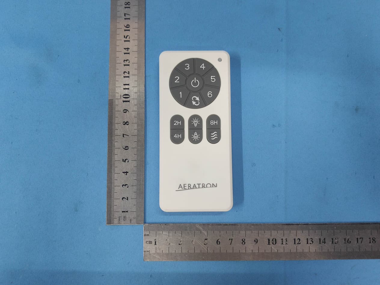
2AAZPDC7
Nov 10, 2020REMOTE CONTROL
Equipment Class
DSC - Part 15 Security/Remote Control Transmitter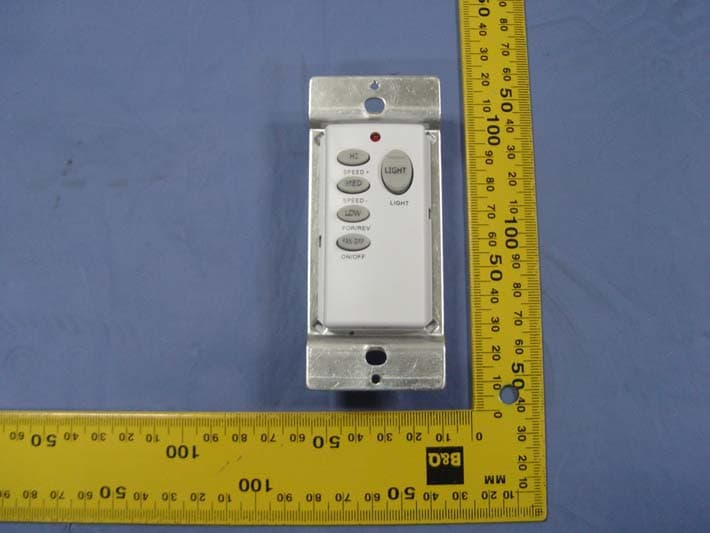
2AAZPFAN55T
Jan 27, 2016REMOTE CONTROL
Equipment Class
DSC - Part 15 Security/Remote Control Transmitter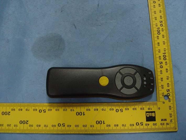
2AAZPFAN61T4SP
Sep 27, 2015REMOTE CONTROL
Equipment Class
DSC - Part 15 Security/Remote Control Transmitter