2AB47TVAC16000CDigital Wireless Surveillance System
ABUS USA LLC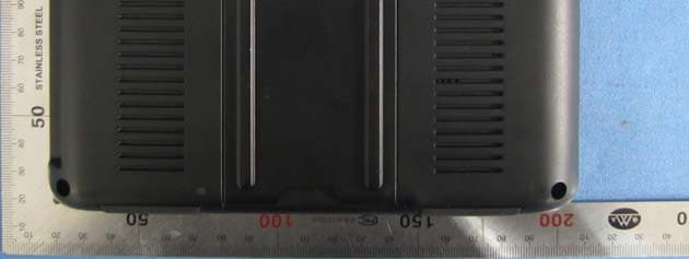
Click to zoom
Application Details
- Equipment Class
- DSS - Part 15 Spread Spectrum Transmitter
- Date of Grant
- May 06, 2014
- Application Purpose
- Original Equipment
- Date of Application
- May 06, 2014
- Equipment Note
- Digital Wireless Surveillance System
- Frequency Range
- 2414.25000000 - 2461.50000000
- Company
- ABUS USA LLC
- Country
- United States
Documents & Files
Document Text
Text extracted from the exhibit documents filed with the FCC. Open a document above to read the original.
Users Manual
TVAC16000C US User guide FR PT Manual de instruções ES Manual de instrucciones You can find important information and FAQs about this and other products on the website www.abus.com/plug-and-play Version 04/2014 2 This user manual contains important information for the installation and operation of the TVAC16000C Home Surveillance System. Please take special care to store this manual for future reference. A list of contents with the corresponding page number can be found in the index on page 9. commande du système de surveillance du domicile TVAC16000C. Veuillez conserver ce manuel pour une utilisation ultérieure. Vous trouverez une liste des thèmes à la table des matières avec mention de la page correspondante à la page 47. Este manual de instruções contém informação importante sobre a instalação e funcionamento do Sistema de Vigilância Doméstica TVAC16000C. Por favor, tenha o cuidado de guardar este manual para consulta futura. Uma lista de conteúdos com o respetivo número da página pode ser consultada no índice na página 86. Este manual de instruccionescontiene información importante para la instalación y el uso del sistema de vigilancia doméstica TVAC16000C. Asegúrese de guardar este manual para futuras consultas. En el índice de la página 126 encontrará un listado de los contenidos con las páginas donde podrá consultarlos. English Français Português Español TVAC16000C 7" Home Video Surveillance System, Touchscreen & Mobile App User manual Version 04/2014 Original user guide in English. Retain for future reference! 4 English Introduction Dear Customer, Thank you for purchasing the ABUS TVAC16000C Home Surveillance System. To ensure optimum performance and condition of this system is maintained, please read carefully the enclosed operating manual. This operating manual is meant to guide you through the process of operating the TVAC16000C Home Surveillance System. This relevant safety information. In the event you have questions regarding the system, installation or operating procedures please consult your local authorized dealer or our customer service team. ABUS USA, LLC surveillance products are not manufactured and/or sold with the intent to be used for illegal and federal law. For further information on video and audio recording legal requirements, please consult your local, state and federal law. Thank you, ABUS USA, LLC Data storage is subject to national data privacy guidelines. Disclaimer This user guide has been produced with the greatest of care. Should you discover any missing information or inaccuracies, please contact us under the address shown on the back of the manual. ABUS USA, LLC does not accept any liability for technical and typographical errors, and reserves the right to make changes to the product and user guide at any time and without prior warning. ABUS USA, LLC is not liable or responsible for direct or indirect damage resulting from the equipment, performance and use of this product. No forms of guarantee are accepted for the contents of this document. ABUS USA LLC. products are not manufactured and/or sold with the intent to be used for illegal purposes. ABUS USA LLC. e to be in compliance with all local, state and federal law. For further information on video surveillance and audio recording legal requirements, please consult your local, state and federal law. © 2014, All rights allowed by law are hereby reserved. 5 English Explanation of symbols The triangular high voltage symbol is used to warn of the risk of injury or health hazards (e.g. caused by electric shock). This triangular with exclamation mark warning symbol indicates important notes in the operating instructions which should be observed. This symbol indicates special information bulletins and notes on the operation of the unit. Important safety information All warranty claims are invalid in the event of damage caused by operating the system in non-compliance with this user guide. ABUS USA LLC cannot be held liable for resulting damages. In the event of material or personal damage caused by improper operation or non- compliance with the safety information, we cannot be held liable. All warranty claims are voided in such cases. This device has been manufactured in accordance with international safety standards. Please read the following safety instructions carefully. Safety information 1. Power supply 110 V AC voltage, 60 Hz (using a power supply unit for 5 V DC) Only operate this device using a power source which supplies the grid voltage specified on the type plate. If you are unsure which voltage is supplied at the installation location, contact your power supply company. Disconnect the device from the power supply before carrying out maintenance or installation work. The power supplies are only for indoor usage. 2. Overloading Avoid overloading electrical sockets, extension cables and adapters, as this can result in fires or electric shocks. 3. Liquids Make sure that no liquids of any type are able to enter the device. 4. Cleaning Only use a damp cloth to clean the device. Do not use corrosive cleaning materials. Disconnect the device from the power supply while doing so. 5. Accessories Only connect devices that are suitable for the intended purpose. Otherwise, hazardous situations or damage to the device can occur. 6. Installation position This device is suitable both for operation in protected outdoor areas as well as indoors. The product may be damaged if it is dropped, even from a low height. Install the device so that no direct sunlight can shine on the image sensor. Pay attention to the installation instructions in the corresponding section of this user guide. Never place the device close to heaters, stoves, other sources of heat, or in direct sunlight. Only operate the device at locations where temperatures within the permitted ambient temperature range of 14 °F to 122 °F prevail. Outside the predetermined temperature range operation is possible, but can not be guaranteed. 6 English 7. …
Text truncated - open the document above for the full version.
Cover Letter(s)
ABUS USA LLC 23910 N. 19th Ave., Unit #56, Phoenix, AZ 85085-1850 DATE :2014-4-14 Nemko Canada Inc 303 River Road Ottawa, Ontario, Canada K1V 1H2 Attn: Director of Certification Authority to Act as Agent On our behalf, I appoint Hans.Hu of Global United Technology Services Co., Ltd. 2nd Floor, Block No.2, Laodong Industrial Zone, Xixiang Road Baoan District Shenzhen Guangdong (Name and address) to act as our agent in the preparation of this application for equipment certification. I certify that submitted documents properly describe the device or system for which equipment certification is sought. I also certify that each unit manufactured, imported or marketed, as defined in the Federal Communications Commission’s regulations will have affixed to it a label identical to that submitted for approval with this application. For instances where our authorized agent signs the application for certification on our behalf, I acknowledge that all responsibility for complying with the terms and conditions for certification, as specified by Nemko Canada Inc, still resides with ABUS USA LLC and 23910 N. 19th Ave., Unit #56, Phoenix, AZ 85085-1850 ( applicant name and address). Dated this / Day of 04/14/2014 / Agency agreement expiration date: 04/14/2015 By: Zac Roy Twight Signature Printed Title: CEO On behalf of : ABUS USA LLC Telephone: (623) 516-9933
Cover Letter(s)
ABUS USA LLC 23910 N. 19th Ave., Unit #56, Phoenix, AZ 85085-1850 DATE 2013-4-14 Equipment Autorisation Division Federal Communications Commission 7435 Oakland Mills Road Columbia, MD 21046 FCC ID: 2AB47TVAC16000C Product Name: Digital Wireless Surveillance System Request for Confidentiality Pursuant to Sections 0.457 and 0.459 of the commissions rules, we hereby request that the following documents be held confidential: Schematics Block diagram Operational Description These materials contain trade secrets and proprietary information and are not customarily released to the public. The public disclosure of this information might be harmful to the company and provide unjustified benefits to our competitors. Dated this / Day of 04/14/2014 / By: Zac Roy Twight Signature Printed Title: CEO On behalf of : ABUS USA LL C Telephone: (623) 516-9933
External Photos
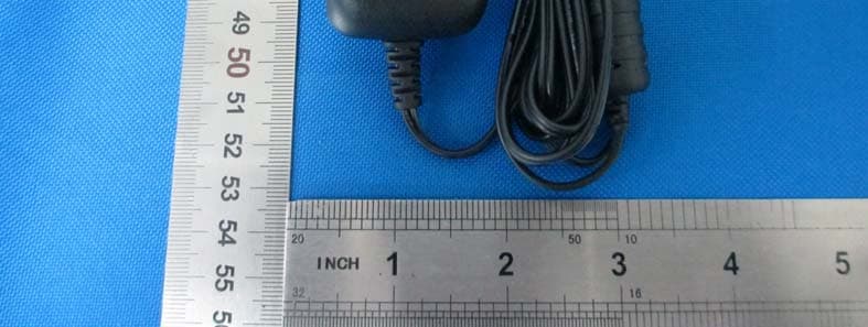
Adapter1 Adapter2 Adapter3 Adapter1 Adapter2 Adapter3
ID Label/Location Info
Label location
RF Exposure Info
FCC ID:2AB47TVAC16000C The device has a standalone transmission. According to KDB 447498 section 4.3.1, the 1-g SAR test exclusion thresholds at test separation distances≤ 50 mm are determined by: [(max. power of channel, including tune-up tolerance, mW)/(min. test separation distance, mm)]·[√f(GHz)] ≤ 3.0 The maximum tune-up limit power is 8.25 dBm(6.68mW) @ 2.41425GHz For the head and body SAR, use 5mm as the conservative minimum test separation distance, [(max. power of channel, including tune-up tolerance, mW)/(min. test separation distance, mm)]·[√f(GHz)] =2.076≤ 3.0 So standalone SAR measurements are not required for both head and body.
Test Report
Global United Technology Services Co., Ltd. Report No.: GTSE14030034101 Authorized Signature: Robinson Lo Laboratory Manager This report details the results of the testing carried out on one sample. The results contained in this test report do not relate to other samples of the same product and does not permit the use of the GTS product certification mark. The manufacturer should ensure that all products in series production are in conformity with the product sample detailed in this report. This report may only be reproduced and distributed in full. If the product in this report is used in any configuration other than that detailed in the report, the manufacturer must ensure the new system complies with all relevant standards. Any mention of GTS or testing done by GTS in connection with, distribution or use of the product described in this report must be approved by GTS in writing. This document cannot be reproduced except in full, without prior written approval of the Company. Any unauthorized alteration, forgery or falsification of the content or appearance of this document is unlawful and offenders may be prosecuted to the fullest extent of the law. Unless otherwise stated the results shown in this test report refer only to the sample(s) tested and such sample(s) are retained for 90 days only. 1 Cover Page FCC Report Applicant: ABUS USA LLC Address of Applicant: 23910 N. 19th Ave., Unit #56, Phoenix, AZ 85085-1850 United States Equipment Under Test (EUT) Product Name: Digital Wireless Surveillance System Model No.: TVAC16000C-Monitor FCC ID: 2AB47TVAC16000C Applicable standards: FCC CFR Title 47 Part 15 Subpart C Section 15.247:2013 Date of sample receipt: March 17, 2014 Date of Test: March 30-April 16, 2014 Date of report issued: April 16, 2014 Test Result : PASS * * In the configuration tested, the EUT complied with the standards specified above. Report No.: GTSE14030034101 Global United Technology Services Co., Ltd. Project No.: GTSE140300341RF 2nd Floor, Block No.2, Laodong Industrial Zone, Xixiang Road Baoan District, Shenzhen, China 518102 Telephone: +86 (0) 755 2779 8480 Fax: +86 (0) 755 2779 8960 Page 2 of 45 2 Version Version No. Date Description 00 April 16, 2014 Original Prepared By: Date: April 16, 2014 Project Engineer Check By: Date: April 16, 2014 Reviewer Report No.: GTSE14030034101 Global United Technology Services Co., Ltd. Project No.: GTSE140300341RF 2nd Floor, Block No.2, Laodong Industrial Zone, Xixiang Road Baoan District, Shenzhen, China 518102 Telephone: +86 (0) 755 2779 8480 Fax: +86 (0) 755 2779 8960 Page 3 of 45 3 Contents Page 1 COVER PAGE .......................................................................................................................................... 1 2 VERSION .................................................................................................................................................. 2 3 CONTENTS .............................................................................................................................................. 3 4 TEST SUMMARY ..................................................................................................................................... 4 5 GENERAL INFORMATION ...................................................................................................................... 5 5.1 CLIENT INFORMATION .......................................................................................................................... 5 5.2 GENERAL DESCRIPTION OF EUT ......................................................................................................... 5 5.3 TEST MODE ........................................................................................................................................ 7 5.4 TEST FACILITY .................................................................................................................................... 7 5.5 TEST LOCATION .................................................................................................................................. 7 5.6 OTHER INFORMATION REQUESTED BY THE CUSTOMER ......................................................................... 7 5.7 DESCRIPTION OF SUPPORT UNITS ....................................................................................................... 7 6 TEST INSTRUMENTS LIST ..................................................................................................................... 8 7 TEST RESULTS AND MEASUREMENT DATA ...................................................................................... 9 7.1 ANTENNA REQUIREMENT ..................................................................................................................... 9 7.2 CONDUCTED EMISSIONS ................................................................................................................... 10 7.3 CONDUCTED PEAK OUTPUT POWER .................................................................................................. 13 7.4 20DB EMISSION BANDWIDTH ............................................................................................................. 15 7.5 CARRIER FREQUENCIES SEPARATION ................................................................................................ 17 7.6 HOPPING CHANNEL NUMBER ............................................................................................................. 19 7.7 DWELL TIME ..................................................................................................................................... 20 7.8 BAND EDGE ...................................................................................................................................... 24 7.8.1 Conducted Emission Method ..................................................................................................... 24 7.8.2 Radiated Emission Method ...............................................…
Text truncated - open the document above for the full version.
Test Setup Photos
Radiated Emission Conducted Emission
Contact Information
Applicant
Zac Roy Twight(CEO)
Test Firm
Global United Technology Service Co., LtdRobinson Lo
Technical Specifications
| # | Rule Parts | Frequency Range | Power Output |
|---|---|---|---|
| 1 | 15C | 2.41 GHz - 2.46 GHz | 6.68 mW |
Other Applications from ABUS USA LLC
2AB47TVAC19000C
Oct 28, 2014WLAN Pan/Tilt Camera&App
Equipment Class
DTS - Digital Transmission System
2AB47TVAC15000C
May 06, 2014Digital Wireless Surveillance System
Equipment Class
DSS - Part 15 Spread Spectrum Transmitter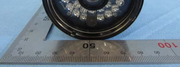
2AB47TVAC15010C
Apr 29, 2014Digital Wireless Camera
Equipment Class
DSS - Part 15 Spread Spectrum Transmitter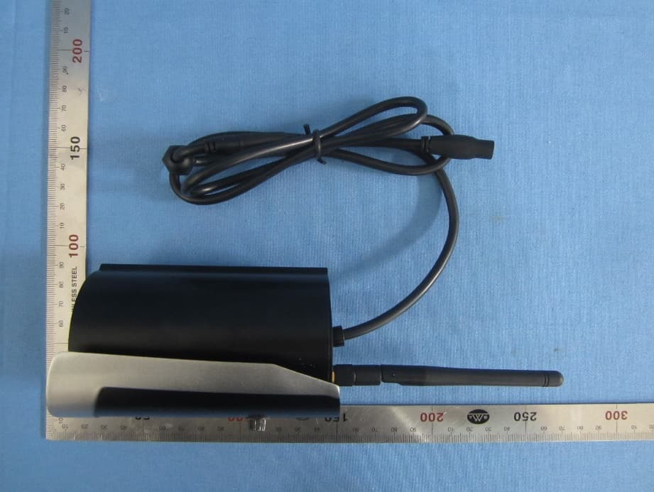
2AB47TVAC16010C
Apr 27, 2014Digital Wireless Camera
Equipment Class
DSS - Part 15 Spread Spectrum Transmitter