2AB4J-LED-CFlexible lighting products
Regalideas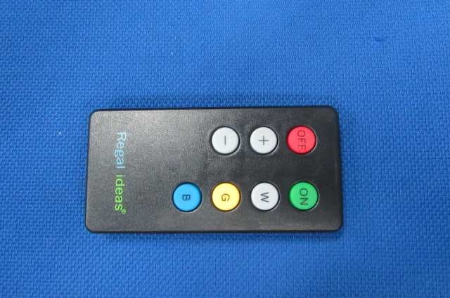
Click to zoom
Application Details
- Equipment Class
- DSC - Part 15 Security/Remote Control Transmitter
- Date of Grant
- Aug 14, 2014
- Application Purpose
- Original Equipment
- Date of Application
- Aug 14, 2014
- Equipment Note
- Flexible lighting products
- Frequency Range
- 315.00000000 - 315.00000000
- Company
- Regalideas
- Country
- United States
Documents & Files
Document Text
Text extracted from the exhibit documents filed with the FCC. Open a document above to read the original.
Users Manual
LED installation -Inspect all railing posts to check that they are the current version with 1/2 “ predrilled holes in the post in the exact location shown in diagram A . Older versions of railing posts may not have pre-drilled holes or have smaller holes in a different location. Drill ½” holes in correct location for all older version posts. 2 1/8” Ø 0.5” Diagram A Regal post - The LED lighting system can be installed in Regal railing systems with glass or locking picket systems supplied after 2007. Pickets or glass will need to be removed in existing systems in order to install the LED lighting strips. -One power adaptor can run a maximum of 10 lighting strips. -Do not kink the LED strip during installation. Although the strips are flexible, extreme bending may damage the circuitry and cause the lights to malfunction. -For ease of installation, run LED strip through any connecting posts or corners before removing the cover from adhesive backing. Installation of the lighting system will begin at an end post that terminates or begins the railing system. This post will house the power adaptor and RF receiver. Drill a ½” hole in decking directly under the center of the railing post that will house the power supply and RF receiver. Run 4’-6’ of the power supply cord up through the hole in the deck. Remove the post cap from the railing post. Feed the power supply cord into center hole in the bottom base plate and run it up through to the top of the post. Connect power cord to the “AC IN” plug of power adaptor. Connect the RF control unit to the “DC OUT” plug of adaptor. Secure post and install top and bottom rails following railing system instructions. See diagram B to electrical outletAC INDC OUTRF CONTROLERLED STRIP (MALE END) Next, feed the male end of the first LED strip into the ½” pre-drilled hole in top post bracket. Connect the LED strip to the plug on the RF control unit ensuring that the lighted side of the strip is aligned to the make it waterproof and to prevent the connections from pulling apart. Peel the cover from the plastic adhesive and wrap this protector around the connection. Remove cover from adhesive backing on the LED strip and firmly press the strip along the upper side of the top rail track. Connect male end of next strip to female end of previous strip. Wrap the connection with the connection protector. Repeat these steps for remainder of the lighting installation. At the end of the installation there may be excess LED strip. The excess can sit inside the last post or the strips can be cut only where indicated by the cut symbol. Test the lighting system at this point by plugging LED power cord in and turning it on with the RF remote control and testing each of the various functions. The remote will control the on/off, three brightness levels and color settings of white, blue and gold. Installing glass with LED lighting Note: Vinyl glass gasket and rubber blocks for bottom rail are sold separately. Insert standard vinyl gasket (GVIL) into bottom rails only and position rubber blocks following standard railing instructions. Install glass panels by first sliding the glass up inside the top rail and then down into the bottom rail. Secure the glass into top rail by pushing one piece of the 2 piece LED glass gaskets inside top rail channel on each side of the glass. See diagram C. Diagram C Installing pickets with LED lighting Using 4” clear spacers supplied with the LED-P package for the top rail, install pickets following the standard railing instructions. Installing LED using UAB’s for custom angles on decks. Attach round backing plates of angle bracket to post following the “Universal angle bracket (UAB) for custom angles” section of railing instructions. Drill a ½” hole in the post just below the upper round backing plate for LED strip to pass through post. Complete installation of UAB and install top and bottom rails. Continue installation of LED lighting. Installing LED lighting with stair railing. Attach round backing of angle brackets following the angle bracket (UAB) on stairs section of standard railing instructions. Drill a ½” hole in post just below the upper round backing plate for LED strip to pass through post. Complete installation of UAB and install top and bottom rails. Install LED strip in stair railing. For stair pickets, use the 5” clear spacers supplied in the LED-SP package for the top rail and install pickets following standard instructions. For stair glass, use the spacers and gasket strips in the top rail as supplied in the LED-SG package and install glass according to standard railing instructions. INSTRUCTION MANUAL 1. Products picture 2. Function Declaration 1 、 、、 、 OFF: Power off 2 、 、、 、 ON: Power ON and LED lighting lamp with a color of light 3 、 、、 、 W : :: : White Color 4 、 、、 、 G : :: : Golden Color 5 、 、、 、 B : :: : Blue Color 6 、+ 、+、+ 、+ : LED brightness enhancing 7 、 、、 、– –– – : LED brightness reduced 3. Battery type: CR2032 4. This device complies with Industry Canada license-exempt RSS standard(s). Operation is subject to the following two conditions: (1) this device may not cause interference, and (2) this device must accept any interference, including interference that may cause undesired operation of the device. Le présentappareilestconforme aux CNR d'Industrie Canada applicables aux appareils radio exempts de licence. L'exploitationestautorisée aux deux conditions suivantes : (1) l'appareil ne doit pas produire de brouillage, et (2) l'utilisateur de l'appareildoit accepter tout brouillage radioélectriquesubi, mêmesi le brouillageest susceptible d'encompromettre le fonctionnement. 5. This device complies with Part 15 of the FCC Rules. Operation is subject to the following two conditions: (1) this device may not cause harmful interference, and (2) this device must accept any interference received, including interference that may cause undesired operation. 6. Warning: Changes or modifications to this unit not expressly approved …
Text truncated - open the document above for the full version.
Block Diagram
Block Diagram 模板 模板模板 模板 要求 要求要求 要求: :: : 1. 1. 1. 1. IC ICIC IC需有名称和它的工作频率或内部时钟频率 需有名称和它的工作频率或内部时钟频率需有名称和它的工作频率或内部时钟频率 需有名称和它的工作频率或内部时钟频率和晶振频率 和晶振频率和晶振频率 和晶振频率。 。。 。 2 22 2. .. .需有箭头走向 需有箭头走向需有箭头走向 需有箭头走向。 。。 。
Operational Description
Technical Description模板 模板模板 模板 Part 1 :电池供电,CR2032 DC3.0V Power by Battery, CR2032 DC3.0V Part 2:键盘输入 Keyboard Input Part 3:MCU 处理键盘信息,编码,传输编码数据 Keyboard data coding and transmition are processed by MCU Part 4 :发射天线,由F113 产生315MHZ 振荡频率由天线发射 Antenna transmit 315 MHz RF generated by F113 transmitter IC Part 5 :接收编码数据,输入到F113MCU 6端口,再经过F113 调频 315MHZ 由端口1和3组合 传输到天线部份 Coded data which input to the Pin6 of F113 IC, will be frequency modulated with 315MHz and transmitted to the Antenna thru Pin1 and Pin3. Antenna Used: 超外差 Super-Heterodyne An integral antenna has been used. 要求 要求要求 要求: :: : 1. 1.1. 1. 应描述出整个产品的工作原理 应描述出整个产品的工作原理应描述出整个产品的工作原理 应描述出整个产品的工作原理。 。。 。 2 22 2. .. .如产品为 如产品为如产品为 如产品为RF RFRF RF产品 产品产品 产品, ,, ,则应有 则应有则应有 则应有RF RFRF RF部份技术描述 部份技术描述部份技术描述 部份技术描述。 。。 。
Operational Description
MICRF113 300MHz to 450MHz +10dBm ASK Transmitter in SOT23 QwikRadio is a registered trademark of Micrel, Inc. Micrel Inc. • 2180 Fortune Drive • San Jose, CA 95131 • USA • tel +1 (408) 944-0800 • fax + 1 (408) 474-1000 • http://www.micrel.com November 2010 M9999-112310 General Description The MICRF113 is a high-performance, easy-to-use, single- chip ASK Transmitter IC for remote wireless applications in the 300MHz to 450MHz frequency band. This transmitter IC is a true “data-in, antenna-out” monolithic device. MICRF113 has three strong attributes: power delivery, operating voltage and operating temperature. In terms of power, the MICRF113 is capable of delivering +10dBm into a 50Ω load. This power level enables a small form factor transmitter (lossy antenna) such as a key fob transmitter to operate near the maximum limit of transmission regulations. In terms of operating voltage, the MICRF113 operates from 1.8V to 3.6V. Many transmitter ICs in the same frequency band stop operating below 2.0V. The MICRF113 will work with most batteries to the end of their useful limits. In terms of operating temperature, the MICRF113 operates from −40°C to +85°C. The MICRF113 is easy to use. It requires a reference frequency (RF carrier frequency divided by 32 times) generated from a crystal with a few additional external parts to create a complete versatile transmitter. The MICRF113 operates with Amplitude Shift Keying/On- Off Keyed (ASK/OOK) UHF receiver types from wide-band super-regenerative radios to narrow-band, high- performance super-heterodyne receivers. The MICRF113’s maximum ASK bit rate is 20kbps (minimum pulse width of 50μs at ASK pin). The MICRF113 transmitter solution is ideal for industrial and consumer applications where simplicity and form factor are important. Data sheets and support documentation can be found on Micrel’s web site at: www.micrel.com . Features • Complete UHF ASK transmitter • Frequency range 300MHz to 450MHz • Bit rates up to 20kbps • Output power up to 10dBm • Low external part count • Low voltage operation (down to 1.8V) • Operate with crystals or ceramic resonators • 6-pin SOT23 Applications • Fan Controllers • Remote Power Switches • Multimedia Remote Control • Remote Sensor Data Links • Infrared Transmitter Replacement Ordering Information Part Number Temperature Range Package MICRF113YM6 −40°C to +85°C SOT23-6 Micrel, Inc. MICRF113 November 2010 2 M9999-112310 Typical Application Figure 1. Typical Application Circuit for 433.92MHz and 315MHz (component values for 315MHz in parenthesis) Pin Configuration Pin Description Pin Number MSOP-6 Pin Name Pin Function 1 PAOUT PA output 2 VSS Ground 3 VDD Positive Power Supply Voltage (Input) 4 XTLOUT Crystal Out (Output): Reference Oscillator Output Connection. 5 XTLIN Crystal In (Input): Reference Oscillator Input Connection. 6 ASK ASK DATA Input Micrel, Inc. MICRF113 November 2010 3 M9999-112310 Absolute Maximum Ratings (1) Supply Voltage V DD .....................................................+5.0V Voltage on PA OUT ........................................................+7.2V Voltage on I/O Pins ............................ V SS – 0.3 to V DD + 0.3 Storage Temperature Range ...................−65°C to + 150°C Lead Temperature (soldering, 10s)......................... + 300°C ESD Rating (3) .................................................................. 2kV Operating Ratings (2) Supply Voltage V DD .......................................... 1.8V to 3.6V Ambient Operating Temperature (T A ) ......... –40°C to +85°C Transmitter Frequency Range ............. 300MHz to 450MHz Electrical Characteristics (4) V DD = 3.0V, T A = 25°C, Freq REFOSC = 13.560MHz. Bold values indicate –40°C to 85°C unless otherwise noted. 2kbps bit rate, 50Ω load. Parameter Condition Min. Typ. Max. Units Power Supply @ 315MHz, POUT = +10dBm 12.3 Mark Supply Current I MARK , V ASK = 3.0V @ 433.92MHz, P OUT = +10dBm 12.5 mA @ 315MHz 2 SPACE Supply Current, I SPACE , V ASK = 0V @ 433.92 MHz 2 mA RF Output Section and Modulation Limits @315MHz (4) 10 Output Power Level, POUT ASK "mark" @433.92MHz (4) 10 dBm @ 630MHz (4) 2nd harm. −39 Harmonics Output for 315MHz @945MHz (4) 3rd harm. −53 dBc @ 867.84MHz (4) 2nd harm. −55 Harmonics Output for 433.92MHz @1301.76MHz (4) 3rd harm. −55 dBc Extinction Ratio for ASK 70 dBc ASK Modulation Encoded Bit Rate 20 kbps @315MHz (6) <700 Occupied Bandwidth @433.92MHz (6) <1000 kHz VCO Section @ 100kHz from Carrier −76 315MHz Single-Side Band Phase Noise @ 1000kHz from Carrier −79 dBc/Hz @ 100kHz from Carrier −72 433.92MHz Single-Side Band Phase Noise @ 1000kHz from Carrier −81 dBc/Hz Notes: 1. Exceeding the absolute maximum rating may damage the device. 2. The device is not guaranteed to function outside its operating rating. 3. Devices are ESD sensitive. Handling precautions recommended. Human body model, 1.5k in series with 100pF. 4. Measured using Test Circuit in Figure 2. 5. Dependent on crystal 6. RBW = 100kHz, OBW measured at −20dBc. Micrel, Inc. MICRF113 November 2010 4 M9999-112310 Electrical Characteristics (4) (Continued) V DD = 3.0V, T A = 25°C, Freq REFOSC = 13.560MHz. Bold values indicate –40°C to 85°C unless otherwise noted. 2kbps bit rate, 50Ω load. Parameter Condition Min. Typ. Max. Units Reference Oscillator Section XTLIN, XTLOUT Pin capacitance 2 pF External Capacitance From each side of the crystal to GND 18 pF Oscillator Startup Time (5) Crystal: HC49S 300 μs Digital / Control Section Output Blanking VDD transition from LOW to HIGH 500 μs High (V IH ) 0.8 × V DD Digital Input ASK Pin Low (V IL ) 0.2 × V DD V High (V IH ) 0.05 Digital Input Leakage Current ASK Pin Low (V IL ) 0.05 μA Undervoltage Lock Out (UVLO) 1.6 V Micrel, Inc. MICRF113 November 2010 5 M9999-112310 Test Circuit Figure 2. MICRF113 Test Circuit with 50Ω Output Micrel, Inc. MICRF113 November 2010 6 M9999-112310 Typical Characteristics − MICRF113 50Ω Test Board 315MHz OBW, ASK = 2kbps 315MHz OBW, ASK = 20kbps CW Max Power @ 3V, 31…
Text truncated - open the document above for the full version.
Schematics
Circuit模板 模板模板 模板 要求 要求要求 要求: :: : 1. 1.1. 1. 每个元器件应有名称和参数值 每个元器件应有名称和参数值每个元器件应有名称和参数值 每个元器件应有名称和参数值。 。。 。 2 22 2. .. .如产品为 如产品为如产品为 如产品为RF RFRF RF产品 产品产品 产品, ,, ,则应有 则应有则应有 则应有Antenna AntennaAntenna Antenna, ,, ,Antenna AntennaAntenna Antenna上标明所使用的频率 上标明所使用的频率上标明所使用的频率 上标明所使用的频率。 。。 。
Test Report
Report No.: 140305007GZU-001 Issued: 2014-8-04 FCC ID: 2AB4J-LED-C Page 2 of 20 CONTENT TEST REPORT ........................................................................................................................................................... 1 CONTENT ................................................................................................................................................................... 2 1.0 Summary of Test ............................................................................................................................................ 3 2.0 General Description ....................................................................................................................................... 4 2.1 Product Description ........................................................................................................................ 4 2.3 Test Methodology ........................................................................................................................... 5 2.4 Test Facility .................................................................................................................................... 5 3.0 System Test Configuration ............................................................................................................................. 6 3.1 Justification .................................................................................................................................... 6 3.2 EUT Exercising Software ............................................................................................................... 6 3.3 Special Accessories ......................................................................................................................... 7 3.4 Measurement Uncertainty ............................................................................................................... 7 3.5 Equipment Modification ................................................................................................................. 7 3.6 Support Equipment List and Description ........................................................................................ 7 4.0 Measurement Results ..................................................................................................................................... 8 4.1 Antenna Requirement: .................................................................................................................... 8 4.2 Radiated Emissions......................................................................................................................... 9 4.3 Occupied Bandwidth .................................................................................................................... 16 4.4 Dwell Time: .................................................................................................................................. 18 5.0 Test Equipment List ..................................................................................................................................... 20 Report No.: 140305007GZU-001 Issued: 2014-8-04 FCC ID: 2AB4J-LED-C Page 3 of 20 1.0 Summary of Test TEST TEST REQUIREMENT TEST METHOD RESULT Radiated Emission FCC PART 15 section 15.231(b) ANSI C 63.10: Clause 6.4, 6.5 and 6.6 PASS Occupied Bandwidth FCC PART 15 section 15.231(c) ANSI C 63.10: Clause 6.9 PASS Dwell Time FCC PART 15 section 15.231(a) FCC PART 15: Section 15.231(a) PASS Remark: N/A: not applicable. Refer to the relative section for the details. EUT: In this whole report EUT means Equipment Under Test. Tx: In this whole report Tx (or tx) means Transmitter. Rx: In this whole report Rx (or rx) means Receiver. RF: In this whole report RF means Radio Frequency. ANSI C63.10: the detail version is ANSI C63.10:2009 in the whole report. Report No.: 140305007GZU-001 Issued: 2014-8-04 FCC ID: 2AB4J-LED-C Page 4 of 20 2.0 General Description 2.1 Product Description Operating Frequency 315 MHz Type of Modulation: ASK modulated by internal signal Antenna Type Integral Antenna gain: 0 dBi Function: Remote control LED Lighting System colour change and on or off Power Supply: AC 120V 60 Hz for LED Lighting system DC 3.0 V for Remote controller Power cord: 0.9 m x 2 wires unscreened AC supply cable Report No.: 140305007GZU-001 Issued: 2014-8-04 FCC ID: 2AB4J-LED-C Page 5 of 20 2.3 Test Methodology Radiated emission measurement was performed according to the procedures in ANSI C63.10:2009. Radiated emission measurement was performed in semi-anechoic chamber For radiated emission measurement, preliminary scans and final tests were performed in the semi- anechoic chamber to determine the worst case modes. All radiated tests were performed at an antenna to EUT distance of 3 meters, unless stated otherwise. 2.4 Test Facility All of the tests are performed at: Intertek Testing Services Shenzhen Ltd. Guangzhou Branch Block E, No.7-2 Guang Dong Software Science Park, Caipin Road, Guangzhou Science City, GETDD Guangzhou, China. This test facility and site measurement data have been fully placed on file with the FCC, test firm registration number is 549654. Report No.: 140305007GZU-001 Issued: 2014-8-04 FCC ID: 2AB4J-LED-C Page 6 of 20 3.0 System Test Configuration 3.1 Justification For emissions testing, the equipment under test (EUT) setup to transmit continuously to simplify the measurement methodology. Care was taken to ensure proper power supply voltages during testing. During testing, the remote controller is power by DC 3V. The signal is maximized through rotation and placement in the three orthogonal axes. The antenna height and polarization are varied during the search for maximum signal level. The antenna height is varied from 1 to 4 meters. Radiated emissions are taken at three meters unless the signal level is too low for measurement at that distance. If necessary, a pre-amplifier is used and/or the test is conducted at a…
Text truncated - open the document above for the full version.
Contact Information
Applicant
Dwayne blandford
Technical Contact
Intertek Testing Services Shenzhen Ltd.Guangzhou BSky Zhu
[email protected]86-20-82139691
Block E, No.7-2 Guang Dong Software Science Park, · Guangzhou, Guangdong · China
Test Firm
Intertek Testing Services Shenzhen Ltd.strong yao
[email protected]8628219940
Technical Specifications
| # | Rule Parts | Frequency Range | Power Output |
|---|---|---|---|
| 1 | 15.231 | 315 MHz - 315 MHz | - |
Other Applications from Regalideas
2AB4J-LED-C-1
Aug 14, 2014Flexible lighting products
Equipment Class
CYY - Communications Receiver used w/Pt 15 Transmitter