2AB4J-LED-C-1Flexible lighting products
Regalideas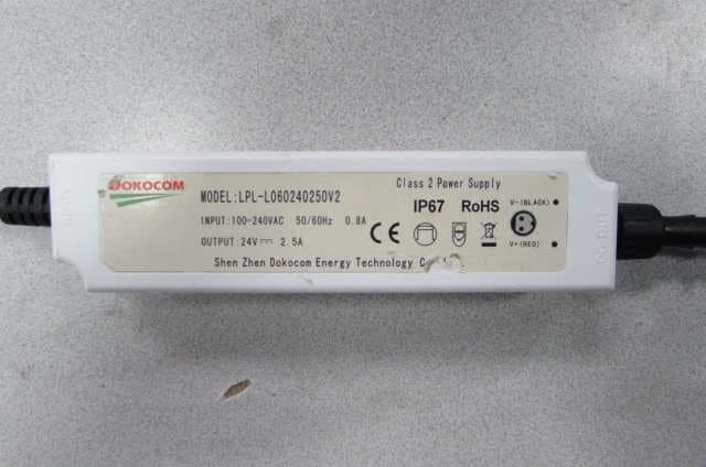
Click to zoom
Application Details
- Equipment Class
- CYY - Communications Receiver used w/Pt 15 Transmitter
- Date of Grant
- Aug 14, 2014
- Application Purpose
- Original Equipment
- Date of Application
- Aug 13, 2014
- Equipment Note
- Flexible lighting products
- Frequency Range
- 315.00000000 - 315.00000000
- Company
- Regalideas
- Country
- United States
Documents & Files
Document Text
Text extracted from the exhibit documents filed with the FCC. Open a document above to read the original.
Users Manual
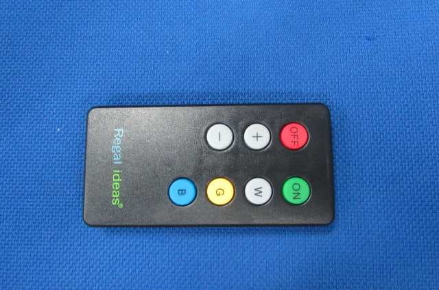
LED installation -Inspect all railing posts to check that they are the current version with 1/2 “ predrilled holes in the post in the exact location shown in diagram A . Older versions of railing posts may not have pre-drilled holes or have smaller holes in a different location. Drill ½” holes in correct location for all older version posts. 2 1/8” Ø 0.5” Diagram A Regal post - The LED lighting system can be installed in Regal railing systems with glass or locking picket systems supplied after 2007. Pickets or glass will need to be removed in existing systems in order to install the LED lighting strips. -One power adaptor can run a maximum of 10 lighting strips. -Do not kink the LED strip during installation. Although the strips are flexible, extreme bending may damage the circuitry and cause the lights to malfunction. -For ease of installation, run LED strip through any connecting posts or corners before removing the cover from adhesive backing. Installation of the lighting system will begin at an end post that terminates or begins the railing system. This post will house the power adaptor and RF receiver. Drill a ½” hole in decking directly under the center of the railing post that will house the power supply and RF receiver. Run 4’-6’ of the power supply cord up through the hole in the deck. Remove the post cap from the railing post. Feed the power supply cord into center hole in the bottom base plate and run it up through to the top of the post. Connect power cord to the “AC IN” plug of power adaptor. Connect the RF control unit to the “DC OUT” plug of adaptor. Secure post and install top and bottom rails following railing system instructions. See diagram B to electrical outletAC INDC OUTRF CONTROLERLED STRIP (MALE END) Next, feed the male end of the first LED strip into the ½” pre-drilled hole in top post bracket. Connect the LED strip to the plug on the RF control unit ensuring that the lighted side of the strip is aligned to the make it waterproof and to prevent the connections from pulling apart. Peel the cover from the plastic adhesive and wrap this protector around the connection. Remove cover from adhesive backing on the LED strip and firmly press the strip along the upper side of the top rail track. Connect male end of next strip to female end of previous strip. Wrap the connection with the connection protector. Repeat these steps for remainder of the lighting installation. At the end of the installation there may be excess LED strip. The excess can sit inside the last post or the strips can be cut only where indicated by the cut symbol. Test the lighting system at this point by plugging LED power cord in and turning it on with the RF remote control and testing each of the various functions. The remote will control the on/off, three brightness levels and color settings of white, blue and gold. Installing glass with LED lighting Note: Vinyl glass gasket and rubber blocks for bottom rail are sold separately. Insert standard vinyl gasket (GVIL) into bottom rails only and position rubber blocks following standard railing instructions. Install glass panels by first sliding the glass up inside the top rail and then down into the bottom rail. Secure the glass into top rail by pushing one piece of the 2 piece LED glass gaskets inside top rail channel on each side of the glass. See diagram C. Diagram C Installing pickets with LED lighting Using 4” clear spacers supplied with the LED-P package for the top rail, install pickets following the standard railing instructions. Installing LED using UAB’s for custom angles on decks. Attach round backing plates of angle bracket to post following the “Universal angle bracket (UAB) for custom angles” section of railing instructions. Drill a ½” hole in the post just below the upper round backing plate for LED strip to pass through post. Complete installation of UAB and install top and bottom rails. Continue installation of LED lighting. Installing LED lighting with stair railing. Attach round backing of angle brackets following the angle bracket (UAB) on stairs section of standard railing instructions. Drill a ½” hole in post just below the upper round backing plate for LED strip to pass through post. Complete installation of UAB and install top and bottom rails. Install LED strip in stair railing. For stair pickets, use the 5” clear spacers supplied in the LED-SP package for the top rail and install pickets following standard instructions. For stair glass, use the spacers and gasket strips in the top rail as supplied in the LED-SG package and install glass according to standard railing instructions. INSTRUCTION MANUAL 1. Products picture 2. Function Declaration 1 、 、、 、 OFF: Power off 2 、 、、 、 ON: Power ON and LED lighting lamp with a color of light 3 、 、、 、 W : :: : White Color 4 、 、、 、 G : :: : Golden Color 5 、 、、 、 B : :: : Blue Color 6 、+ 、+、+ 、+ : LED brightness enhancing 7 、 、、 、– –– – : LED brightness reduced 3. Battery type: CR2032 4. This device complies with Industry Canada license-exempt RSS standard(s). Operation is subject to the following two conditions: (1) this device may not cause interference, and (2) this device must accept any interference, including interference that may cause undesired operation of the device. Le présentappareilestconforme aux CNR d'Industrie Canada applicables aux appareils radio exempts de licence. L'exploitationestautorisée aux deux conditions suivantes : (1) l'appareil ne doit pas produire de brouillage, et (2) l'utilisateur de l'appareildoit accepter tout brouillage radioélectriquesubi, mêmesi le brouillageest susceptible d'encompromettre le fonctionnement. 5. This device complies with Part 15 of the FCC Rules. Operation is subject to the following two conditions: (1) this device may not cause harmful interference, and (2) this device must accept any interference received, including interference that may cause undesired operation. 6. Warning: Changes or modifications to this unit not expressly approved …
Text truncated - open the document above for the full version.
Block Diagram
Block Diagram 模板 模板模板 模板 要求 要求要求 要求: :: : 1. 1. 1. 1. IC ICIC IC需有名称和它的工作频率或内部时钟频率 需有名称和它的工作频率或内部时钟频率需有名称和它的工作频率或内部时钟频率 需有名称和它的工作频率或内部时钟频率和晶振频率 和晶振频率和晶振频率 和晶振频率。 。。 。 2 22 2. .. .需有箭头走向 需有箭头走向需有箭头走向 需有箭头走向。 。。 。
Operational Description
Technical Description模板 模板模板 模板 Part 1 :MCU 解码,控制LED 输出不同状态 MCU decode and control LED output status Part 2:RF 接收模块数据端口 RF Receiver Module Data Port Part 3:三基色LED 接线端口 Three Color LED Output Port Part 4 :直流输入DC24V端口, 稳压模块输出DC+5V 给MCU 供电 C24V Source is regulated down to DC5V to power the MCU Part 5:三基色LED 功能驱动模块 Three Color LED Function Module Part 6:天线接收315MHZ 数据信号 Antenna receive 315MHz data signal Part 7 :SYN470R MCU端口4接收无线信号315MHZ,经过解调分析,由端口10输出500HZ数 据信号给主MCU 解码。 315MHz signal received from Pin4 of SYN470R IC will be demodulated and covert to 500Hz data signal and output to MCU Antenna Used: 超外差 Super-Heterodyne An integral antenna has been used. 要求 要求要求 要求: :: : 1. 1.1. 1. 应描述出整个产品的工作原理 应描述出整个产品的工作原理应描述出整个产品的工作原理 应描述出整个产品的工作原理。 。。 。 2 22 2. .. .如产品为 如产品为如产品为 如产品为RF RFRF RF产品 产品产品 产品, ,, ,则应有 则应有则应有 则应有RF RFRF RF部份技术描述 部份技术描述部份技术描述 部份技术描述。 。。 。
Schematics
Circuit模板 模板模板 模板 1 2 3 4 56 ABCD 6 5 4 3 2 1 D CBA Title Number Revision Size B Date: 27-Mar-2014 Sheet of File: G:\xms unch ic\ 尚时服务器 \ 研发中心 \ 项目开发 \ 广东欣会 \RF 遥控器 \SSCTRL-DL K00 35 \ 设 计 Drawn By: J1PHONEJACK2 Vin 1 GND 2 +5V 3 U1MC7805T C20.01uF Q3S855 R82K R9200R710K P-W Q2SS8550 R52K P-B Q1SS8550 R22K P-G Q6STN454 123 J2 P-WP-BP-G C3 1000uF/10v C147uF/50V 1234 J3 VDD VDD VDD VDD VDD VDD R131K R121K R111K LED_W LED_VCC LED_W LED_B LED_G LED_VCC R6200R410K Q5STN454 LED_B R3200R110K Q4STN454 LED_G D11LED_W R21RES2 LED_VCCLED_W D12LED_B R22RES2 LED_VCCLED_B D13LED_G R23RES2 LED_VCCLED_G 紫色字体内是外接负载,不在本电路板上。 白光 蓝光 黄光 编码数据 p50 1 p67 2 p66 3 vdd 4 p65 5 p64 6 p63 7 p61 9 p60 10 vss 11 p53 12 p52 13 p51 14 p62 8 osc0osc1 rst U1 EM78P173NSO14 0.1UF DATA DATA 10K 10K 10K 10K 10K 10K 10K 10K 10K 10K 3K3K 0.1UF 输出控制频率: 500HZ 输出控制频率: 500HZ 输出控制频率: 500HZ MCU: EM78P173NSO14 内部时钟: 4.0MHZ RF315 接收模块:接收频率 31 5MHZ DATA IN :889HZ
Test Report
Report No.: 140305007GZU-002 Issued: 2014-8- 04 FCC ID: 2AB4J-LED-C-1 Page 2 of 14 CONTENT TEST REPORT ....................................................................................................................................................................... 1 CONTENT ............................................................................................................................................................................... 2 1 TEST RESULTS SUMMARY ...................................................................................................................................... 3 2 TEST RESULTS CONCLUSION ................................................................................................................................ 4 3 LABORATORY MEASUREMENTS .......................................................................................................................... 5 4 TEST RESULTS ............................................................................................................................................................ 6 4.1 CONDUCTED DISTURBANCE VOLTAGE AT MAINS PORTS .............................................................................................. 6 4.1.1 Used Test Equipment ......................................................................................................................................... 6 4.1.2 Block Diagram of Test Setup ............................................................................................................................. 6 4.1.3 Test Setup and Procedure .................................................................................................................................. 6 4.1.4 Limit ................................................................................................................................................................... 7 4.1.5 Test Data............................................................................................................................................................ 8 4.1.6 Emission Curve .................................................................................................................................................. 9 4.1.7 Measurement Uncertainty.................................................................................................................................. 9 4.2 RADIATED EMISSION (30 MHZ -2000 MHZ) .............................................................................................................. 10 4.2.1 Used Test Equipment ....................................................................................................................................... 10 4.2.2 Block Diagram of Test Setup ........................................................................................................................... 10 4.2.3 Field Strength Calculation............................................................................................................................... 11 4.2.4 Test Setup and Procedure ................................................................................................................................ 12 4.2.5 Limit ................................................................................................................................................................. 12 4.2.6 Test Data.......................................................................................................................................................... 13 4.2.7 Test Curve ........................................................................................................................................................ 14 4.2.8 Measurement uncertainty ................................................................................................................................ 14 Report No.: 140305007GZU-002 Issued: 2014-8- 04 FCC ID: 2AB4J-LED-C-1 Page 3 of 14 1 TEST RESULTS SUMMARY Classification of EUT: Class B Test Item Standard Result Conducted disturbance voltage at mains ports FCC Part 15: 2013, Subpart B Pass Radiated emission (30 MHz–1 GHz) FCC Part 15: 2013, Subpart B Pass Radiated emission (Above 1 GHz) FCC Part 15: 2013, Subpart B Pass Remark: Reference publication is used for methods of measurement: ANSI C63.4:2009 Remark: 1. When determining the test results, measurement uncertainty of tests has been considered. Report No.: 140305007GZU-002 Issued: 2014-8- 04 FCC ID: 2AB4J-LED-C-1 Page 4 of 14 2 Test Results Conclusion (with Justification) RE: EMC Testing Pursuant to FCC Part 15, Subpart B Performed On the Flexible lighting products, Model: LED Lighting System We tested the Flexible lighting products, Model: LED Lighting System, to determine if it was in compliance with the relevant FCC rules as marked on the Test Results Summary. We found that the unit met the requirement of FCC Part 15, Subpart B when tested as received. The worst case’s test data was presented in this test report. The equipment under test (EUT) is controlled by a remote controller; the controller is an intentional radiator using 315MHz frequency. The controller option of this receiver is subject to Certification procedure. The production units are required to conform to the initial sample as received when the units are placed on the market. FCC ID: 2AB4J-LED-C-1 Page 5 of 14 3 LABORATORY MEASUREMENTS Configuration Information Equipment Under Test (EUT): Flexible lighting products Model: LED Lighting System Serial No. Not Labeled Support Equipment: N/A Rated Voltage: 120V, 60Hz Condition of Environment: Temperature : 22~28C Relative Humidity: 35~60% Atmosphere Pressure 86~106kPa Notes: The EMI measurements had been made in the operating mode producing the largest emission in the frequency band being investigated consistent with normal applications. An attempt had been made to maximize the emission by varying the configuration of the EUT. All…
Text truncated - open the document above for the full version.
Contact Information
Applicant
Dwayne blandford
Technical Contact
Intertek Testing Services Shenzhen Ltd.Guangzhou BSky Zhu
[email protected]86-20-82139691
Block E, No.7-2 Guang Dong Software Science Park, · Guangzhou · China
Non-Technical Contact
Intertek Testing Services Shenzhen Ltd.Guangzhou BSky Zhu
[email protected]86-20-82139691
Test Firm
Intertek Testing Services Shenzhen Ltd.strong yao
[email protected]8628219940
Technical Specifications
| # | Rule Parts | Frequency Range | Power Output |
|---|---|---|---|
| 1 | 15B | 315 MHz - 315 MHz | - |
Other Applications from Regalideas
2AB4J-LED-C
Aug 14, 2014Flexible lighting products
Equipment Class
DSC - Part 15 Security/Remote Control Transmitter