2AB4QGA222GALARM SYSTEM
SHENZHEN OAK ELECTRONIC TECH. CO., LTD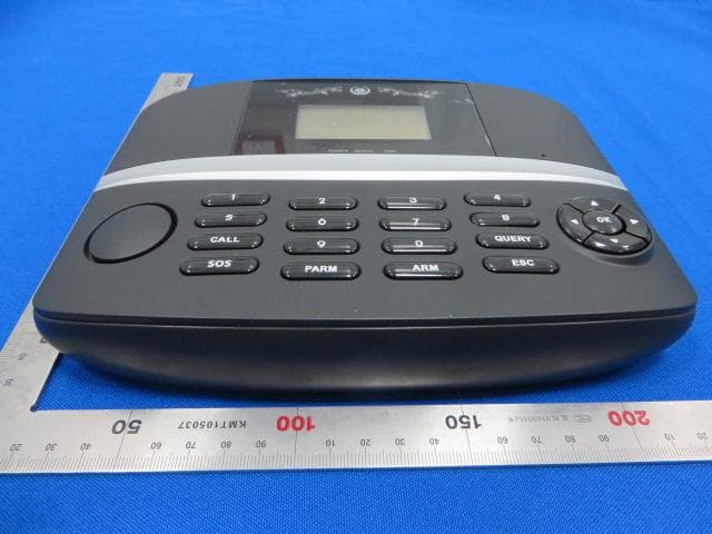
Click to zoom
Application Details
- Equipment Class
- PCB - PCS Licensed Transmitter
- Date of Grant
- Apr 07, 2014
- Application Purpose
- Original Equipment
- Date of Application
- Apr 07, 2014
- Equipment Note
- ALARM SYSTEM
- Frequency Range
- 1850.20000000 - 1909.80000000
- Country
- China
Documents & Files
Document Text
Text extracted from the exhibit documents filed with the FCC. Open a document above to read the original.
Users Manual
GA222G USER MANUAL Chapter 1 Installation and setting Panel installation Panel configuration Back wall function interface configuration Door sensor installation PIR detector installation instruction Remote control Chapter 2 Operation and setting instruction Instruction of alarm panel Main interface Dial interface Alarm SMS numbers Elder help call setting Add remote controller Add defense zoon setting Recording setting System setting Time setting Timely arm/disarm Patrol setting Linkage defense zone setting Defense zone function instruction Chapter 3 Main function description Panel disarm Away arm Stay arm Answer alarm call Remote control SOS System dialing function Alarm records check Chapter 4 System trouble shooting Chapter 5 APP operation instruction Warranty card Function and Specifications Function: LCD screen with clock display, simple and elegant Compatible with Smartphone APP (IOS, Android) 4 wired and 10 wireless defense zones, 2-way defense alarm output, different zones different function application Support maximum 90 wireless detectors Can be used as a telephone by using keypad to make calls Remote control the device to arm, disarm by sending SMS Can preset 6 phrases phone numbers: when alarming, system will make alarm call to these numbers automatically Can preset 3 phrases SMS numbers: when alarming, system will send alarming SMS automatically Can preset 3 phrases SOS phone numbers Wireless learning code: easy to add additional wireless accessories 6 groups of timely arm/disarm by week, convenient for users and alarm center to control the system. 20 seconds voice recording message Record checking: the device can store 50 alarm records Built-in high capacity battery, SMS alert for power failure or low voltage Support timely patrol, can be elder monitor, security inspection, warehouse inspection. Technical parameters : Power supply: AC=220V±10% DC=5V Static current: ≤60MA Alarm current: ≤450MA GSM frequency :850/900/1800/1900MHZ Wireless receiving frequency: 433MHZ External siren voice: 110db Standard package including: 1*main panel 2*remote controller 1*wireless door sensor 1*wireless PIR detector 1*external wired small siren 1*power supply 1*backup battery 1* user manual Chapter 1 Installation Panel installation 1 .Install in center area of defense zone to make sure get all wireless sensor signal very well. 2 .Stay away large metal objects or high frequency interference household appliance, It’s better stall in hidden space Panel configuration 1. Main frame screen: 128x64, support English and Chinese display 2. Status LED: power (red): insert the external power supply, it lights, if remove, it goes out. set(green):enter into setup interface, it lights, exit the interface, it goes out. Signal(green):when receive valid RF signals, the signal light blinks. Alarm(red):when the panel alarms, it lights, when disarm, it goes out. 3.Touch keypad: ESC:exit or turn back ENTER:confirm or OK CALL:in system disarming state, it can achieve phone function. ARM:press it; system be AWAY ARM status STAY:press it; system be STAY ARM status SOS: emergency alarm ↑↓← →:choice for up/down/left/right and move Back wall function interface configuration 4. Functional interface 1 SHOW wired LED light, on in arm, off in disarm 2 GND Grounded cord(negative) 3 ARM Wired arm swift, from On to off is arm, from off to on is disarm 4 GND Grounded cord(negative) 5 T1 Wired sensor 1 positive 6 GND Grounded cord(negative) 7 T2 Wired sensor 2 positive 8 GND Grounded cord(negative) 9 T3 Wired sensor 3 positive RED BLACK SIREN WIRED SENSOR 10 GND Grounded cord(negative) 11 T4 Wired sensor 4 positive 12 OUT2 Out put 2 or remote control output 2 13 OUT1 Out put 1 or remote control output 1 14 +12V Power output 15 BELL Wired siren 5. Built-in battery switch 6. SIM card slot 2. Door sensor installation Door sensor photo: Installation diagram: Door sensor installation instruction: 1) Door sensor is to monitor door/window open and close, Mount the sensor on the door frame and the magnet on the door by use random enclosed double-side adhesive, and suggest use glass glue or super glue to fix because viscosity of adhesive will be decreased after long term use. 2) Line up part A and part B on the same place and try stay close, the distance should be less than 10mm. 3) o get best wireless transmission range, please pull out antenna and placed vertically. 4) Do not close to metal or directly installed on metal to avoid effect door sensor performance. 3. PIR detector installation instruction: Wireless PIR detector installation instructions: 1) PIR detector can monitor if have people moving in a certain range, when installation, mount the sensor on the face of wall, above ground 2 to 2.2 meters, adjust angle, face with detection area. 2) More sensitive for horizontal movement in a certain range, less sensitive for vertical movement. So PIR orientation should be vertical with people walk direction. 3) To minimize false alarms, do not expose to the place which temperature change fast, high air velocity and pet passed, such as outdoors, air conditioners, fireplace and sun. 4) Do not have large obstruction within detection area. Remote controller 1) arm for main panel with all accessories 2) stay arm when host or other people at home, parts of detection area invalid or disarm 3) send “SOS” to main panel 4) disarm for main panel with all accessories Normally height and angle Top view Alert range Chapter 2 Operation and setting instruction Operation instruction 1. Instruction of alarm panel: 1) Insert SIM card 2) Power on the power adapter, alarm panel will start self-inspection and display screen information 3) Waiting alarm panel connect the network well, GSM signal strength at least 3 which means connection successful, otherwise, weak signal will affect normal use. 2. Main interface 1) GSM signal bars:display current GSM signal strength 2) Battery Charge:display current battery charge. 3) Panel St…
Text truncated - open the document above for the full version.
Cover Letter(s)
SHENZHEN OAK ELECTRONIC TECH. CO., LTD ------------------------------------------------------------------------------------------------------------------------- Date: March 25, 2014 Federal Communications Commission Authorization and Evaluation Division FCC ID: 2AB4QGA222G ATTESTATION FCC ID: 2AB4QGA222G Product: Alarm System Model: GA222G, GA100G, GA102G, TA100G, GT333G, GA007G We don't provide any controls or software to allow operation outside the USA frequency band when we sell this product in USA. Sincerely, __________________ Signature: Jack Liu / G.M. Date: 2014-03-25
Cover Letter(s)
SHENZHEN OAK ELECTRONIC TECH. CO., LTD Room 403, Huafeng Xinan Business Building 45th Zone, Baoan District, Shenzhen, P.R.C. ----------------------------------------------------------------------------------------------------------------------------------- Declaration of Authorization We Name: SHENZHEN OAK ELECTRONIC TECH. CO., LTD Address: Room 403, Huafeng Xinan Business Building 45th Zone, Baoan District, Shenzhen, P.R.C. Declare that: Name Representative of agent: Wu Jian Agent Company name: MRT Technology (Suzhou) Co., Ltd Address: D8 Building, Youxin Industrial Park, No.2 Tian'edang Rd., Wuzhong Economic Development Zone, City: Suzhou Country China is authorized to apply for Certification of the following product(s): Product description:Alarm System FCC ID:2AB4QGA222G Model:GA222G, GA100G, GA102G, TA100G, GT333G, GA007G on our behalf. --------------------------------------------------- Signature: Jack Liu / G.M. Date: 2014-3-25
Cover Letter(s)
SHENZHEN OAK ELECTRONIC TECH. CO., LTD Room 403, Huafeng Xinan Business Building 45th Zone, Baoan District, Shenzhen, P.R.C. ------------------------------------------------------------------------------------------------------------------------------- March 25, 2014 Federal Communications Commission Authorization and Evaluation Division Confidentiality Request regarding application for certification of FCC ID: 2AB4QGA222G Pursuant to Sections 0.457 and 0.459 of the Commission’s Rules, we hereby request confidential treatment of information accompanying this application as outlined below: Exhibit Type File Name Block Diagram 2AB4QGA222G_FCC_BlcokDiagram.pdf Schematic Diagram 2AB4QGA222G_FCC_SchematicDiagram.pdf Circuit Description 2AB4QGA222G_FCC_OperationalDescription.pdf BOM List 2AB4QGA222G_FCC_BOM List.pdf Tune-up Procedure 2AB4QGA222G_FCC_Tune-up Procedure.pdf The above materials contain trade secrets and proprietary information not customarily released to the public. The public disclosure of these materials may be harmful to the applicant and provide unjustified benefits to its competitors.
External Photos
1 of 4 External Photo (1) EUT Photo (2) EUT Photo (3) EUT Photo (4) EUT Photo (5) EUT Photo (6) EUT Photo (7) EUT Photo
ID Label/Location Info
Label Label Location SHENZHEN OAK ELECTRONIC TECH. CO., LTD Alarm System M/N: GA222G This device complies with Part 15 of the FCC Rules. Operation is subject to the following two conditions: (1) this device may not cause harmful interference, and (2) this device must accept any interference received, including interference that may cause undesired operation. FCC ID: 2AB4QGA222G
Internal Photos
1 of 6 Internal Photo (1) EUT Photo (2) EUT Photo (3) EUT Photo (4) EUT Photo (5) EUT Photo (6) EUT Photo (7) EUT Photo (8) EUT Photo (9) EUT Photo (10) EUT Photo (11) EUT Photo (12) EUT Photo
Test Report
MRT Technology (Suzhou) Co., Ltd Report No.: 1403RSU02701 Phone: +86-512-66308358 Report Version: V01 Fax: +86-512-66308368 Issue Date: 04-02-2014 Web: www.mrt-cert.com FCC ID: 2AB4QGA222G Page Number: 1 of 35 FCC ID: 2AB4QGA222G APPLICANT: SHENZHEN OAK ELECTRONIC TECH. CO., LTD Application Type: Certification Product: Alarm System Model No.: GA222G, GA100G, GA102G, TA100G, GT333G, GA007G FCC Classification: PCS Licensed Transmitter (PCB) FCC Rule Part(s): Part2, Part22 Subpart H, Part24 Subpart E Test Procedure(s): ANSI/TIA-603-C-2004, KDB 971168 D01v02r01 Test Date: March 22 ~ April 01, 2014 MEASUREMENT REPORT FCC PART 22H & 24E Reviewed By : ( Sunny Sun ) Approved By : ( Robin Wu ) The test results relate only to the samples tested. This equipment has been shown to be capable of compliance with the applicable technical standards as indicated in the measurement report and was tested in accordance with the measurement procedures specified in §2.947. Test results reported herein relate only to the item(s) tested. The test report shall not be reproduced except in full without the written approval of MRT Technology (Suzhou) Co., Ltd. Report No.: 1403RSU02701 FCC ID: 2AB4QGA222G Page Number: 2 of 35 CONTENTS Description Page Revision History ............................................................................................................................. 4 §2.1033 General Information ......................................................................................................... 5 1. INTRODUCTION ..................................................................................................................... 6 1.1. Scope ........................................................................................................................... 6 1.2. MRT Test Location ....................................................................................................... 6 2. PRODUCT INFORMATION ..................................................................................................... 7 2.1. Equipment Description .................................................................................................. 7 2.2. Device Capabilities ....................................................................................................... 7 2.3. Test Configuration ........................................................................................................ 7 2.4. EMI Suppression Device(s)/Modifications ..................................................................... 7 3. DESCRIPTION OF TEST ........................................................................................................ 8 3.1. Evaluation Procedure ................................................................................................... 8 3.2. Cellular – Base Frequency Blocks ................................................................................ 8 3.3. Cellular – Mobile Frequency Blocks .............................................................................. 8 3.4. PCS – Base Frequency Blocks ..................................................................................... 8 3.5. PCS – Base Frequency Blocks ..................................................................................... 9 3.6. Occupied Bandwidth ..................................................................................................... 9 3.7. Spurious and Harmonic Emissions at Antenna Terminal ............................................... 9 3.8. Radiated Power and Radiated Spurious Emissions ...................................................... 9 3.9. Peak-Average Ratio .................................................................................................... 11 3.10. Frequency Stability / Temperature Variation ............................................................... 11 4. TEST EQUIPMENT CALIBRATION DATA ............................................................................ 12 5. SAMPLE CALCULATIONS ................................................................................................... 13 6. MEASUREMENT UNCERTAINTY ......................................................................................... 14 7. TEST RESULT ...................................................................................................................... 15 7.1. Summary .................................................................................................................... 15 7.2. OCCUPIED BANDWIDTH .......................................................................................... 16 7.2.1. Test Limit .................................................................................................................... 16 7.2.2. Test Procedure used ................................................................................................... 16 7.2.3. Test Setting ................................................................................................................. 16 7.2.4. Test Setup................................................................................................................... 16 7.2.5. Test Result .................................................................................................................. 17 7.3. Spurious and Harmonic Emissions at Antenna Terminal ............................................. 19 Report No.: 1403RSU02701 FCC ID: 2AB4QGA222G Page Number: 3 of 35 7.3.1. Test Limit .................................................................................................................... 19 7.3.2. Test Procedure Used .................................................................................................. 19 7.3.3. Test Setting ................................................................................................................. 19 7.3.4. Test Setup..........................................................................................…
Text truncated - open the document above for the full version.
Test Setup Photos
1 of 1 RF Test Setup Photo Description: Radiated Emission Test Setup for 30MHz ~ 1GHz Description: Radiated Emission Test Setup for 1GHz ~ 18GHz
Contact Information
Applicant
Jack Liu(G.M.)
Test Firm
MRT Technology (Suzhou) Co., LtdWu Jian
[email protected]86-512-66308358
Technical Specifications
| # | Rule Parts | Frequency Range | Power Output | Emission | Tolerance |
|---|---|---|---|---|---|
| 2 | 24E | 1.85 GHz - 1.91 GHz | 659.00 mW | 246KGXW | 48 Hz |
Other Applications from SHENZHEN OAK ELECTRONIC TECH. CO., LTD

2AB4QN4
Jan 27, 2016Water leak host panel
Equipment Class
PCB - PCS Licensed Transmitter