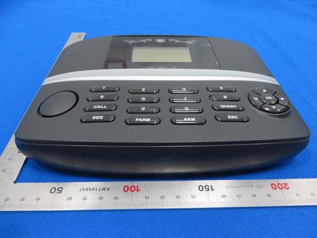
2AB4QN4Water leak host panel
SHENZHEN OAK ELECTRONIC TECH. CO., LTD
Click to zoom
Application Details
- Equipment Class
- PCB - PCS Licensed Transmitter
- Date of Grant
- Jan 27, 2016
- Application Purpose
- Original Equipment
- Date of Application
- Jan 27, 2016
- Equipment Note
- Water leak host panel
- Frequency Range
- 1850.20000000 - 1909.80000000
- Country
- China
Documents & Files
Document Text
Text extracted from the exhibit documents filed with the FCC. Open a document above to read the original.
Users Manual
GSM Water Leak Detection Device Panel Model Number: N4 Sensor Model Number: WS01 In this documentation it is a hardware description for N4 and WS01. Any people and any group do not copy this file without permission for business and technical reference. 2015-09-15 System Diagram This system provide a “Early Water Leak Warning” Service. The below is system diagram. The water leak sensor (WS01) will inspect the water leak status in zones. When get a water leak action, WS01 will send a local alarm signal to the panel (N4) over local wireless ASK433, and N4 will send a SMS to monitor center with WS01 alarm message over GSM channel. At this time the monitor center will send a mail or SMS to home owner or water security server provider. N4 Hardware Description Item Name Part number Spec Appendix 1 MCU GD32F103 8-bit Application Micro Processor Unit 2 Memory 4K MCU built-in RAM 3 Flash 128K MCU built-in Flash 4 Audio OAK-A10 Audio and ASK decode and encode chip, Sample frequency: 64K 5 module UC15A WCDMA/GSM four frequency 6 Battery BT1000 3.7v/1000mAh Li-battery 7 Local wireless ASK-433 ASK mode/433MHz 8 Module Antenna WA-03 PCB Antenna Average: 30dBm 9 ASK Antenna AK-01 Spring Antenna/Cable Antenna -110dBm 10 ASK distance Unobstructed open area 150 Meters 11 Speaker SP-03 Built-in Speaker/8oHm/1w 12 Microphone MP-02 Built-in Microphone 13 Button Service request button 14 Led Status led with two color 15 Power PW-02 +5V/500mA 16 Static Current <20mA Sleep mode 17 Work current <200mA GSM Transmission 18 Temperature Work temperature: -10~60 °C 19 Humidity Work humidity: 15%~95% Architecture N4 Picture Status Description Power On N4 boot from flash. It will get the program from flash to memory, run timer , exception, GPIO, database table initial. And set power inspection, audio channel, ASK433 module channel and GSM module. Then MCU will send some commands to GSM module for GSM network register. When network register finished, the panel enter standby mode. Standby mode In this mode the panel power consumption is lower. MCU enter standby mode and waiting for some external trigger. The trigger is the below. 1. GSM command. 2. ASK433 message. 3. Button operation. Led display N4 have a dual-color led on the front panel, different color is different means. 1. Red on: Mobile network offline 2. Red off: Mobile network online 3. Green on: Arm 4. Green off: Disarm Network Inspection In zero o’clock the panel will send a SMS to identify the mobile network status every day. Use this function to make sure the panel is no problem and give SMS center a network status reference. The SMS like the below. This below SMS means GSM network is no disconnect exception in one day. GSM / DISCONNECT / 0 TIMES Parameter Setting 1. Monitor Center number setting In this system only has one monitor center. All of SMS exchange via panel and monitor center over GSM channel. So in normal working mode the panel only storage one monitor center number in it. But for panel parameter setting a testing/setting number must join the panel firstly. Setting a testing number using any mobile phone Service Password #2# Testing Phone number The service password is the panel service password. The initial is “888888”. Example: 888888#2#13522161431, this operation set the testing number 13522161431. Setting a monitor center number using any mobile phone Service Password #1# Testing Phone number Example: 888888#2#13522161431, this operation set the monitor center number 13522161431. Clear all number using any mobile phone Service Password # Example: 888888#, this operation clear all number in the panel include testing and monitor center number. 2. Sensor setting 1) Ensure the testing number or monitor center number is saved in the panel. 2) Using the testing phone or monitor center number send a sensor zone number (1,2,3,4,5,6,7,8,9), the panel receive this number and sound No.x sensor code is starting. 3) Push the water sensor back plane button to send a code to the panel. The panel will check this code. If the code is presence, the panel sound a tick “di” to tell the customer this code is duplicated. If the code is right, the panel will sound the sensor code. 4) If customer hear the sensor code voice, push the service button and hold 3 seconds, the customer will hear a code successful voice and the sensor code will be save. 5) When sensor code status, push the service button and release it immediately to force the panel exit the sensor code status. 6) When sensor code status, every sensor code time line is 120 second. If the time is up, the panel will exit the sensor code status automatically. 7) When a sensor code is successful, the panel will wait the next sensor code automatically until sensor code exit is reactive. When code sensor number is full (No.5), and finish No.5 sensor save operation and panel give a voice” coding end”. 8) When exit the sensor code status, the panel will send a SMS message to mobile phone to identify this zone code result, like the below. The below SMS means zone 1 code five water sensors and every sensor code is in the list. Zone 1: 1.903B 2.68BA 3.3345 4.B875 5.9D34 9) In power off status push the service button and hold, when power on until hear a “welcome” voice, the whole sensor code will be deleted. 3. Password setting The panel built-in two password. One is Service password for the panel operation, another is super password for restore the service number by system administrator. If you are a system administrator, please contact the system provider for super password. Restore the service password(Only for administrator use, the default is “9795”, not change) Super Password #3# Service Password Example: 9795#3#9987, using this SMS command restore the service password 9987. Change the service number using any mobile phone. Old service Password #0# New Service Password Example: 334576#0#998702, this operation change the service password from 334576 to 998702. 4. Fix disarm When disaster on site and not fixed in …
Text truncated - open the document above for the full version.
Cover Letter(s)
SCS-F18: Project and Product Certification Representative Authorization Letter Page 1 of 2 Rev 5.0 775 Montague Expressway Milpitas, CA 95035 Tel: 408-526-1188 Fax: 408-526-1088 Email: [email protected] Project and Product Certification Representative Authorization Letter Reason for Amendment (current / obsolete) Revision History Approved Date From To Initial Release (obsolete) 1.0 1.0 Nov-14-2006 Revised wording (obsolete) 1.0 2.0 Sept–25-2007 Updated company template (obsolete) 2.0 3.0 Jan-31-2012 Updated letter information (obsolete) 3.0 4.0 May-23-2014 Added FCC ID field (current) 4.0 5.0 Sept 16 2014 SCS-F18: Project and Product Certification Representative Authorization Letter Page 2 of 2 Rev 5.0 SHENZHEN OAK ELECTRONIC TECH. CO., LTD 2015-1-6 To: SIEMIC, INC. 775 Montague Expressway, Milpitas, CA 95035 USA Dear Sir/Madam, Re: Product Certification Representative Authorization Letter We, SHENZHEN OAK ELECTRONIC TECH. CO., LTD hereby authorize SIEMIC, Inc. to act as a Certification Body for certifying for the following project(s): Product description: Water leak host panel model n ame: N4 Trademark: OAK, FCC ID: 2AB4QN4 Sincerely, Client’s signature ‘ Client’s name / title : Jack Liu / G.M. Contact information / address: Room 403, Huafeng Xinan Business Building, 45th Zone, Baoan District, Shenzhen, China
Cover Letter(s)
SCS-F19: Confidentiality Request Letter Page 1 of 2 Rev 5.0 775 Montague Expressway Milpitas, CA 95035 Tel: 408-526-1188 Fax: 408-526-1088 Email: [email protected] Confidentiality Request Letter Reason for Amendment (current / obsolete) Revision History Approved Date From To Initial Release (obsolete) 1.0 1.0 Nov-14-2006 Adding CFR 2.459 (obsolete) 1.0 2.0 August – 11 - 2008 Updated company template& Added text box (obsolete) 2.0 3.0 Jan-31-2012 Added IC confidentiality letter form (obsolete) 3.0 4.0 March-26-2015 Corrections to STC form. Added reference to KDB (current) 4.0 5.0 Nov 19 2015 SCS-F19: Confidentiality Request Letter Page 2 of 2 Rev 5.0 SHENZHEN OAK ELECTRONIC TECH. CO., LTD 2016-1-6 To: Federal Communications Commission Authorization and Evaluation Division 7435 Oakland Mills Road Columbia, MD Subject: Permanent Confidentiality Request for FCC ID: 2AB4QN4 Pursuant to sections 0.457 and 0.459 of CFR 47, we respectfully request permanent confidential treatment of the following Exhibits accompanying this application as: - Block Diagram - Schematics - Operational Description - Tune up Procedurer - BOM The above materials contain trade secrets and proprietary information not customarily released to the public. The public disclosure of these materials may be harmful to the applicant and provide unjustified benefits to its competitors. The applicant understands that disclosure of this application and all accompanying documentation will not be made before the date of the Grant for this application. Sincerely, Client’s name / title : Jack Liu / G.M. Contact information / address: Room 403, Huafeng Xinan Business Building, 45th Zone, Baoan District, Shenzhen, China
ID Label/Location Info
Size:35*25mm M/N: N4 FCC ID: 2AB4QN4 This device complies with part 15 of the FCC Rules. Operation is subject to the condition that this device does not cause harmful interference Label location
Internal Photos
GSM Antenna location 433 RX Antenna location
RF Exposure Info
FCC §15.247 (i), §2.1091 – RF Exposure FCC ID: 2AB4QN4 Applied procedures / limit According to FCC §15.247(i) and §1.1307(b)(1), systems operating under the provisions of this section shall be operated in a manner that ensures that the public is not exposed to radio frequency energy level in excess of the Commission’s guidelines. Limits for Occupational / Controlled Exposure Frequency Range (MHz) Electric Field Strength (E) (V/m) Magnetic Field Strength (H) (A/m) Power Density (S) (mW/ cm 2 ) Averaging Time |E| 2 ,|H| 2 or S (minutes) 0.3-3.0 614 1.63 (100)* 6 3.0-30 1842 / f 4.89 / f (900 / f)* 6 30-300 61.4 0.163 1.0 6 300-1500 F/300 6 1500-100,000 5 6 Note: ƒ is frequency in MHz * = Power density limit is applicable at frequencies greater than 100 MHz Limits for General Population / Uncontrolled Exposure Frequency Range (MHz) Electric Field Strength (E) (V/m) Magnetic Field Strength (H) (A/m) Power Density (S) (mW/ cm 2 ) Averaging Time |E| 2 ,|H| 2 or S (minutes) 0.3-1.34 614 1.63 (100)* 30 1.34-30 824/f 2.19/f (180/f)* 30 30-300 27.5 0.073 0.2 30 300-1500 F/1500 30 1500-100,000 1.0 30 Note: f = frequency in MHz * = Plane-wave equivalent power density MPE PREDICTION Predication of MPE limit at a given distance, Equation from OET Bulletin 65, Edition 97-01 Where: S = power density P = power input to antenna G = power gain of the antenna in the direction of interest relative to an isotropic radiator R = distance to the center of radiation of the antenna, R=0.2m TEST RESULTS Tune up Produce power Maximum peak output power (dBm) Output power to antenna (mW) Antenna Gain (numeric) Power Density (S) (mW/ cm2) Limit of Power Density (S) (mW/ cm2) Result GSM 850 32.0±1 33.0 2238.72 1.26(1.0dBi)0.49972 0.549 Pass PCS1900 30.0±1 31.0 1258.93 1.26(1.0dBi)0.31530 1.000 Pass
Test Report
Shenzhen BCTC Technology Co., Ltd. Report No.: BCTC-151216182 FCC Report Tel: 400-788-9558 0755-33019988 Web:Http://www.bctc-lab.com.cn Page 1 of 46 FCC Test Report FCC ID:2AB4QN4 Product Name: Water leak host panel Trademark: OAK, Model Name: N4 Prepared For: SHENZHEN OAK ELECTRONIC TECH. CO., LTD Address: Room 403, Huafeng Xinan Business Building, 45th Zone, Baoan District, Shenzhen, China Prepared By: Shenzhen BCTC Technology Co., Ltd. Address: NO.101, Yousong Road, Longhua New District, Shenzhen, Guangdong, P.R.China Test Date: Dec. 25 - Dec. 30, 2015 Date of Report: Jan. 4, 2016 Report No.: BCTC-151216182 Shenzhen BCTC Technology Co., Ltd. Report No.: BCTC-151216182 FCC Report Tel: 400-788-9558 0755-33019988 Web:Http://www.bctc-lab.com.cn Page 2 of 46 VERIFICATION OF COMPLIANCE Applicant’s name ................. : SHENZHEN OAK ELECTRONIC TECH. CO., LTD Address ................................. : Room 403, Huafeng Xinan Business Building, 45th Zone, Baoan District, Shenzhen, China Manufacture's Name ............ : SHENZHEN OAK ELECTRONIC TECH. CO., LTD Address ................................. : Room 403, Huafeng Xinan Business Building, 45th Zone, Baoan District, Shenzhen, China Product description Product name ........................ : Water leak host panel Trademark: OAK, Model Name: N4 Test procedure FCC CFR Title 47 Part 2: 2014 FCC CFR Title 47 Part22 Subpart H: 2014 FCC CFR Title 47 Part24 Subpart E: 2014 This device described above has been tested by BCTC, and the test results show that the equipment under test (EUT) is in compliance with the requirements. And it is applicable only to the tested sample identified in the report. This report shall not be reproduced except in full, without the written approval of BCTC, this document may be altered or revised by BCTC, personal only, and shall be noted in the revision of the document. Test Result : Pass Prepared by(Engineer): Reviewer(Supervisor): Approved & Authorized Signer(Manager): This test report is based on a single evaluation of one sample of above mentioned products. It is not permitted to be duplicated in extracts without written approval of Shenzhen BCTC Technology Co., Ltd. Shenzhen BCTC Technology Co., Ltd. Report No.: BCTC-151216182 FCC Report Tel: 400-788-9558 0755-33019988 Web:Http://www.bctc-lab.com.cn Page 3 of 46 TABLE OF CONTENTS Test Report Declaration Page 1. TEST SUMMARY .......................................................................................................................... 4 2. GENERAL PRODUCT INFORMATION .................................................................................... 5 2.1. Product Function .............................................................................................................................. 5 2.2. Description of Device (EUT) .......................................................................................................... 5 2.3. Difference between Model Numbers ............................................................................................... 6 2.4. Independent Operation Modes ......................................................................................................... 6 3. TEST SITES ................................................................................................................................... 7 3.1. Test Facilities ...................................................................................................................................... 7 3.2. List of Test and Measurement Instruments .................................................................................... 8 4. TEST SET-UP AND OPERATION MODES .............................................................................. 9 4.1. Principle of Configuration Selection ................................................................................................. 9 4.2. Block Diagram of Test Set-up ........................................................................................................... 9 4.3. Test Environment: .............................................................................................................................. 9 5. EMISSION TEST RESULTS ..................................................................................................... 10 5.1. Conducted RF Output Power ......................................................................................................... 10 5.2. Peak to Average Radio .................................................................................................................... 11 5.3. -26dB and 99% Occupied Bandwidth ............................................................................................ 13 5.4. Frequency Stability ........................................................................................................................... 17 5.5. Conducted Spurious Emissions ..................................................................................................... 19 5.6. Conducted Out of Band Emissions ................................................................................................ 23 5.7. Transmitter Radiated Power (EIRP/ERP) ....................................................................................... 26 5.8. Radiated Out of Band Emissions ..................................................................................................... 29 5.9. CONDUCTED EMISSION MEASUREMENT ................................................................................. 37 6. PHOTOGRAPHS OF TEST SET-UP ....................................................................................... 41 7. PHOTOGRAPHS OF THE EUT ................................................................................................ 43 Shenzhen BCTC Technology Co., Ltd. Report No.: BCTC-151216182 FCC Report Tel: 400-788-9558 0755-33019988 Web:Http://www.bctc-lab.com.cn Page 4 of 46 1. TEST SUMMARY Test Items Te…
Text truncated - open the document above for the full version.
Test Setup Photos
Conducted Emission Test Radiated Emission Test
Contact Information
Applicant
Jack Liu(G.M.)
Test Firm
Shenzhen BCTC Technology Co., Ltd.James Zhang
Technical Specifications
| # | Rule Parts | Frequency Range | Power Output | Emission | Tolerance |
|---|---|---|---|---|---|
| 2 | 24E | 1.85 GHz - 1.91 GHz | 1.148 W | 323KGXW | 0.0463 ppm |
Other Applications from SHENZHEN OAK ELECTRONIC TECH. CO., LTD
2AB4QGA222G
Apr 07, 2014ALARM SYSTEM
Equipment Class
PCB - PCS Licensed Transmitter