2AB4VAU10sMRT AU10 EMERGENCY PERSONAL LOCATOR DEVICE WITH AIS
Marine Rescue Technologies Ltd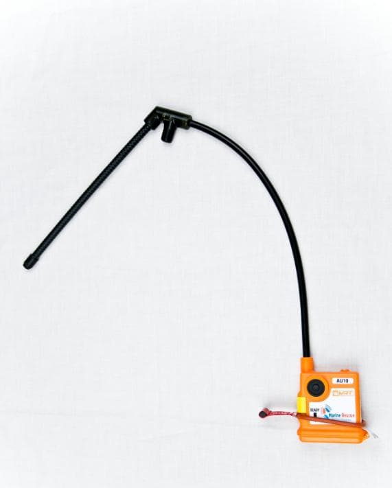
Click to zoom
Application Details
- Equipment Class
- PLB - Personal Locator Beacons
- Date of Grant
- Jun 19, 2014
- Application Purpose
- Original Equipment
- Date of Application
- Mar 31, 2014
- Equipment Note
- sMRT AU10 EMERGENCY PERSONAL LOCATOR DEVICE WITH AIS
- Frequency Range
- 121.50000000 - 162.02500000
- Country
- United Kingdom
Documents & Files
Document Text
Text extracted from the exhibit documents filed with the FCC. Open a document above to read the original.
Users Manual
sMRT AU10 790000024_sMRT AU10 User Manual Version 1.8_20140616 June 2014 User Manual sMRT AU10 User Manual v1.8 MRT Ltd. © 2014 2 Table of Contents IIntroduction 3 IIGlossary of Terms & Acronyms 4 IIIWarnings & Safety Information 5 IVsMRT AU10 Overview 7 1.............................................................................. 8sMRT AU10 Features VsMRT AU10 Operation 10 1.............................................................................. 14Testing the sMRT AU10 VIRecertification and Servicing 17 VIIDeclaration of Conformity 19 VIIIFCC Compliance Information Statement 20 IXWarranty 21 XTerms of Sale 24 XIDisclaimer 34 XIITrademark Notice 35 XIIITechnical Specifications 36 sMRT AU10 User Manual v1.8 MRT Ltd. © 2014 3 1Introduction The following symbols and conventions are used to indicate important information. Always observe these instructions. WARNINGS: Instructions that, if ignored, could result in death or serious personal injury caused by incorrect operation of the equipment. These must be observed for safe operation. CAUTIONS: Instructions that, if ignored, could result in personal injury or material damage caused by incorrect operation of the equipment. These must be observed for safe operation. Important Note: Important instructions that should be adhered to during system operation. Typographic Conventions 1. Hardware features are displayed in bold uppercase letters, e.g. ARMING SWITCH. 2. Operation states are displayed in bold uppercase letters surrounded by square brackets, e.g. [OFF]. Using your sMRT AU10 for the First Time Carefully read the Warnings and Safety Information section in this manual prior to using the sMRT AU10 for the first time. To operate correctly, the sMRT AU10 should be professionally fitted to an MRT approved PFD by a service centre authorised by MRT. Visit the MRT website www.mrtsos.com for specific instructions on accessing the sMRT AU10. Prior to first use perform a full system test to confirm the device is operating correctly. WARNING: DO NOT unzip the main PFD zip. Use the sMRT AU10 access point zip in the life jacket to prepare the device for use. 4 MRT Ltd. © 2014 sMRT AU10 User Manual v1.8 2Glossary of Terms & Acronyms AISAutomatic Identification System: Automatic tracking system used on ships and by vessel traffic services for identifying and locating vessels by electronically exchanging data with other nearby ships, AIS base stations, and satellites. AMSAAustralian Maritime Safety Authority DSC Digital Selective Calling – technology used to automate calling on terrestrial marine radio systems. ECDISElectronic Chart Display and Information System EPIRBEmergency Position Indicating Radio Beacon. FCCUS Federal Communications Commission MAYDAYVoice distress priority message MMSIMaritime Mobile Service Identity (DSC identity number) MSLSMaritime Survivor Locating System PFDPersonal Flotation Device PLDPersonal Locating Device RDFRadio Direction Finding RTCMRadio Technical Commission for Maritime Services SARSearch and Rescue USCGUS Coast Guard VHFVery High Frequency radio band – 30 to 300 MHz. sMRT AU10 User Manual v1.8 MRT Ltd. © 2014 5 3Warnings & Safety Information WARNINGS: The sMRT AU10 is not an EPIRB and its emergency transmissions are not detected by orbiting satellites. The device is a short range Personal Locating Device (PLD), which uses AIS and 121.5MHz Radio Direction Finding (RDF) techniques. Perform a full system test before use. The sMRT AU10 should ONLY be used in an emergency. DELIBERATE MISUSE MAY INCUR A SEVERE PENALTY. Annual inspection and recertification of the sMRT AU10 by MRT Ltd. or an authorised service agent is required every 12 months. DO NOT store or transport the unit in a wet or high moisture environment to avoid accidental activation. Do not dismantle the sMRT AU10 as it contains no user- serviceable parts. DO NOT tamper with the AUTO ACTIVATION WATER SENSOR on the top or bottom of the unit The sMRT AU10 emits radio frequency radiation when in use. Avoid handling the antenna when activated. LIFE JACKET & PERSONAL PROTECTIVE EQUIPMENT (PPE) USAGE WARNINGS: The sMRT AU10 must only be fitted/attached to life jackets approved by MRT Ltd. Only MRT approved attachment kits/pouches are to be used to attach the unit to the life jacket. The sMRT AU10 must be fitted strictly in accordance with the life jacket manufacturer & MRT's instructions as supplied. The sMRT AU10 must only be fitted by an approved service centre authorised by MRT and the life jacket manufacturer. The life jacket is to be serviced according to the manufacturer's specifications. It is the user's responsibility to ensure that any ancillary equipment, such as survival suits/harnesses, PPE, clothing etc., does not interfere with the operation of the sMRT AU10. 6 MRT Ltd. © 2014 sMRT AU10 User Manual v1.8 CAUTION: Do not paint the sMRT AU10 or clean it with aggressive detergents or solvents. Some cleaning materials may damage the seals and affect the integrity of the device. To ensure the sMRT AU10 operates as intended in an emergency: oAvoid dropping the unit. oAvoid leaving the unit unnecessarily in full sun where it may be exposed to excessively high temperatures. oInspect the device periodically for signs of wear and tear, visible cracks or other damage. The sMRT AU10 could save your life, treat it with respect at all times. sMRT AU10 User Manual v1.8 MRT Ltd. © 2014 7 4sMRT AU10 Overview This user manual provides all the information required to operate and test the sMRT AU10 Maritime Survivor Locating Devices. The sMRT AU10 is a dual- operation Personal Locating Device transmitting on the 121.5 MHz search and rescue (SAR) frequency, while simultaneously transmitting GPS position coordinates on AIS channels AIS1 and AIS2. sMRT AU10 Activation When armed, the sMRT AU10 is designed to automatically activate in an emergency when immersed in water. There is an AUTO ACTIVATION WATER SENSOR sensor on the top and bottom of the unit. If the unit is co…
Text truncated - open the document above for the full version.
ID Label/Location Info
We take the SEARCH out of Search and Rescue Marine Rescue Technologies Limited Marshall House, 3 Zarya Court, Grovehill Road, Beverley, East Yorkshire HU17 0JG Tel: +44 (0)1482 679300 | Fax: +44 (0)1482 679145 | Email: [email protected] :Web: www.mrtsos.com Vat number 772782395 Company Registration Number 4202403 AU10 Identification Labels We take the SEARCH out of Search and Rescue Marine Rescue Technologies Limited Marshall House, 3 Zarya Court, Grovehill Road, Beverley, East Yorkshire HU17 0JG Tel: +44 (0)1482 679300 | Fax: +44 (0)1482 679145 | Email: [email protected] :Web: www.mrtsos.com Vat number 772782395 Company Registration Number 4202403 We take the SEARCH out of Search and Rescue Marine Rescue Technologies Limited Marshall House, 3 Zarya Court, Grovehill Road, Beverley, East Yorkshire HU17 0JG Tel: +44 (0)1482 679300 | Fax: +44 (0)1482 679145 | Email: [email protected] :Web: www.mrtsos.com Vat number 772782395 Company Registration Number 4202403
Internal Photos
We take the SEARCH out of Search and Rescue Marine Rescue Technologies Limited Marshall House, 3 Zarya Court, Grovehill Road, Beverley, East Yorkshire HU17 0JG Tel: +44 (0)1482 679300 | Fax: +44 (0)1482 679145 | Email: [email protected] :Web: www.mrtsos.com Vat number 772782395 Company Registration Number 4202403 AU10 PCB VIEW Schematic Ref MT200-S4 MT200-S9 MT200-S5 MT200-S2 We take the SEARCH out of Search and Rescue Marine Rescue Technologies Limited Marshall House, 3 Zarya Court, Grovehill Road, Beverley, East Yorkshire HU17 0JG Tel: +44 (0)1482 679300 | Fax: +44 (0)1482 679145 | Email: [email protected] :Web: www.mrtsos.com Vat number 772782395 Company Registration Number 4202403 Schematic Ref MT200-S4 MT200-S9 MT200-S5 MT200-S2 We take the SEARCH out of Search and Rescue Marine Rescue Technologies Limited Marshall House, 3 Zarya Court, Grovehill Road, Beverley, East Yorkshire HU17 0JG Tel: +44 (0)1482 679300 | Fax: +44 (0)1482 679145 | Email: [email protected] :Web: www.mrtsos.com Vat number 772782395 Company Registration Number 4202403
Operational Description
Declaration of Conformity Name of Manufacturer Importer: Address of Manufacturer Importer: Marine Rescue Technology Limited Marshall House Zarya Court, Grovehill Road Beverley, East Yorkshire HU17 0JG Declares that product: AU10 Maritime Personal Homing Beacon Conform to the R&TTE Directive 1999/5/EC as attested by conformity with the following harmonized standards: EN 302 961-2 V1.2.1: Electromagnetic compatibility and Radio spectrum Matters (ERM);Maritime Personal Homing Beacon intended for use on the frequency 121,5 MHz for search and rescue purposes only; Part 2: Harmonized EN covering the essential requirements of article 3.2 of the R&TTE Directive. EN 300 152-2 V1.1.1: Electromagnetic compatibility and Radio spectrum Matters (ERM); Maritime Emergency Position Indicating Radio Beacons (EPIRBs) intended for use on the frequency 121,5 MHz or the frequencies 121,5 MHz and 243 MHz for homing purposes only; Part 2: Harmonized EN under article 3.2 of the R&TTE Directive. EN 301 489-22 V1.3.1: Electromagnetic compatibility and Radio spectrum Matters (ERM); ElectroMagnetic Compatibility (EMC) standard for radio equipment and services; Part 22: Specific conditions for ground based VHF aeronautical mobile and fixed radio equipment. Conform to the Low Voltage Directive 2006/95/EC as attested by conformity with the following harmonized standard: EN60950-1:2006: Information technology equipment — Safety — Part 1: General requirements. FCC ID: 2AB4VAU10 _ _____________________ Ken Gaunt Director MRT Limited 20 May 2013
Operational Description
We take the SEARCH out of Search and Rescue Page 1 of 12 AU10 FCC Waiver Applicant: Marine Rescue Technologies Ltd Correspondence Reference Number: 45776 Form 731 Confirmation Number: EA596693 Further to your questions 1 &2) below and a request for additional clarification: 1) The waiver exhibit (WT Docket No. 13-99) states that MRT has been granted a waiver to upgrade the device to transmit identify and location information on the international AIS channels at 500mW ERP. It is thus understood that the EUT will radiate no more than 500mW ERP. Other power parameters listed in this application include a conducted output power of 1W, an air band power of 100mW ERP, and a marine band power of 1W EIRP (latter two values from the user manual exhibit). Although it is known that conducted output, ERP, and EIRP values will be different depending upon antenna gain and other system parameters, the large deviation in values requires additional clarification. Furthermore, please elaborate on the difference between the two mentioned ERP values (100mW v. 500mW). i) Overview: The EUT radiates close to 500 mW and it’s conducted output power when measured directly is similarly just under 500 mW. The antenna is a whip with it’s coaxial feed acting as counterpoise. This combination gives a high antenna gain. During testing to RTCM 11901.1:2012 the antenna gain was determined as 2.69 dBi @ 162 MHz. This accounts for the considerable difference between the ERP and EIRP radiated figures. The transmitter output power is reduced for 121.5 MHz transmissions by internal firmware and the corresponding slight reduction in antenna gain at 121.5 MHz means that the AU10 ERP radiated power never exceeds 100 mW. ii) AIS Conducted: The requirements of RTCM 11901.1:2012 clause E.7.2.1.3 means that the antenna gain is added to the conducted measurements and in all cases the AU10 passes the minimum requirement of 27 dBm (500 mW). The corrected values recorded were between 28.062 dBm and 30.007 dBm under all conditions. These values are closer to 1W and this is why the documentation uses 1W as the nominal figure. iii) AIS Radiated: The AU10 radiates no more than 500 mW ERP when tested using ETSI dipole substitution method employed in all ETSI standards. However when tested using the very different method employed by RTCM 11901.1:2012 clause E.7.3 the value recorded was 29.55 dBi (901.36 mW EIRP). Again this is closer to 1W and this is why the documentation uses 1W as the nominal figure. iv) 121.5 MHz Conducted: The AU10’s conducted output power measured at the RF output terminals and without any corrected factors applied falls between 80 and 120 mW. Furthermore this particular test is applied at the factory to all production units. 100mW is stated as the nominal conducted output power. v) 121.5 MHz Radiated: The AU10 antenna gain at this frequency falls slightly and therefore the radiated power measurements made using the dipole substitution method never exceed 100mW ERP. We take the SEARCH out of Search and Rescue Page 2 of 12 2) The Operational Description exhibit contains a file titled Declaration of Conformity. Per 47 CFR 2.1033(c), this document shall contain a detailed description of the modulation system to be used, a description of the modulating wave train, and any other information pertaining to operational capabilities and functions. This would power levels at different bands, antenna gain characteristics, etc. Applications for equipment other than that operating under parts 15 and 18 of the rules shall be accompanied by a technical report containing the following information: (1) The full name and mailing address of the manufacturer of the device and the applicant for certification – see page 4 below. (2) FCC identifier – see pages 4 & 6. (3) A copy of the installation and operating instructions to be furnished the user. A draft copy of the instructions may be submitted if the actual document is not available. The actual document shall be furnished to the FCC when it becomes available – see pages 10 to 16 inclusive of operating manual. (4) Type or types of emission. See page 34 of operating manual. 121.5 MHz = A3X AIS = F1D (5) Frequency range. See page 34 of operating manual. 121.5 MHz (single channel) AIS = 161.975 to 162.025 MHz (6) Range of operating power values or specific operating power levels, and description of any means provided for variation of operating power. See page 34 of operating manual. 121.5 MHz = 100 mW PERP AIS = 1 W EIRP (7) Maximum power rating as defined in the applicable part(s) of the rules. 121.5 MHz = 100 mW PERP maximum (RTCM 11901.1:2012 clause B.3.5.1.6) AIS = max not specified in RTCM 11901.1:2012 annex E. (8) The dc voltages applied to and dc currents into the several elements of the final radio frequency amplifying device for normal operation over the power range. Not applicable (9) Tune-up procedure over the power range, or at specific operating power levels. Not applicable (10) A schematic diagram and a description of all circuitry and devices provided for determining and stabilizing frequency, for suppression of spurious radiation, for limiting modulation, and for limiting power. See attached schematic. Schematic diagram to be supplied is mt200_s5_r1-0(sch).pdf We take the SEARCH out of Search and Rescue Page 3 of 12 RF Frequency reference is X50 on page 12 of schematic. RF Frequency source is ADF4360-9 (U51 on page 12 of schematic.). Spurious filter is parts C77C79, C81, L61L63 & L67 on page 12 of schematic. Modulation is under software control and by the circuitry around U6 on page 11 of schematic. RF Power is under software control and by circuitry around U3U5 on page 11 of schematic. (11) A photograph or drawing of the equipment identification plate or label showing the information to be placed thereon. See pages 5, 6 & 7 of attached and also on pages 8 & 9 of operating manual. (12) Photographs (8′′×10′′) of the equipment of sufficient clarity to reveal equipment constr…
Text truncated - open the document above for the full version.
Operational Description
We take the SEARCH out of Search and Rescue Page 1 of 12 AU10 FCC Waiver Applicant: Marine Rescue Technologies Ltd Correspondence Reference Number: 45776 Form 731 Confirmation Number: EA596693 Further to your questions 1 &2) below and a request for additional clarification: 1) The waiver exhibit (WT Docket No. 13-99) states that MRT has been granted a waiver to upgrade the device to transmit identify and location information on the international AIS channels at 500mW ERP. It is thus understood that the EUT will radiate no more than 500mW ERP. Other power parameters listed in this application include a conducted output power of 1W, an air band power of 100mW ERP, and a marine band power of 1W EIRP (latter two values from the user manual exhibit). Although it is known that conducted output, ERP, and EIRP values will be different depending upon antenna gain and other system parameters, the large deviation in values requires additional clarification. Furthermore, please elaborate on the difference between the two mentioned ERP values (100mW v. 500mW). i) Overview: The EUT radiates close to 500 mW and it’s conducted output power when measured directly is similarly just under 500 mW. The antenna is a whip with it’s coaxial feed acting as counterpoise. This combination gives a high antenna gain. During testing to RTCM 11901.1:2012 the antenna gain was determined as 2.69 dBi @ 162 MHz. This accounts for the considerable difference between the ERP and EIRP radiated figures. The transmitter output power is reduced for 121.5 MHz transmissions by internal firmware and the corresponding slight reduction in antenna gain at 121.5 MHz means that the AU10 ERP radiated power never exceeds 100 mW. ii) AIS Conducted: The requirements of RTCM 11901.1:2012 clause E.7.2.1.3 means that the antenna gain is added to the conducted measurements and in all cases the AU10 passes the minimum requirement of 27 dBm (500 mW). The corrected values recorded were between 28.062 dBm and 30.007 dBm under all conditions. These values are closer to 1W and this is why the documentation uses 1W as the nominal figure. iii) AIS Radiated: The AU10 radiates no more than 500 mW ERP when tested using ETSI dipole substitution method employed in all ETSI standards. However when tested using the very different method employed by RTCM 11901.1:2012 clause E.7.3 the value recorded was 29.55 dBi (901.36 mW EIRP). Again this is closer to 1W and this is why the documentation uses 1W as the nominal figure. iv) 121.5 MHz Conducted: The AU10’s conducted output power measured at the RF output terminals and without any corrected factors applied falls between 80 and 120 mW. Furthermore this particular test is applied at the factory to all production units. 100mW is stated as the nominal conducted output power. v) 121.5 MHz Radiated: The AU10 antenna gain at this frequency falls slightly and therefore the radiated power measurements made using the dipole substitution method never exceed 100mW ERP. We take the SEARCH out of Search and Rescue Page 2 of 12 2) The Operational Description exhibit contains a file titled Declaration of Conformity. Per 47 CFR 2.1033(c), this document shall contain a detailed description of the modulation system to be used, a description of the modulating wave train, and any other information pertaining to operational capabilities and functions. This would power levels at different bands, antenna gain characteristics, etc. Applications for equipment other than that operating under parts 15 and 18 of the rules shall be accompanied by a technical report containing the following information: (1) The full name and mailing address of the manufacturer of the device and the applicant for certification – see page 4 below. (2) FCC identifier – see pages 4 & 6. (3) A copy of the installation and operating instructions to be furnished the user. A draft copy of the instructions may be submitted if the actual document is not available. The actual document shall be furnished to the FCC when it becomes available – see pages 10 to 16 inclusive of operating manual. (4) Type or types of emission. See page 34 of operating manual. 121.5 MHz = A3X AIS = F1D (5) Frequency range. See page 34 of operating manual. 121.5 MHz (single channel) AIS = 161.975 to 162.025 MHz (6) Range of operating power values or specific operating power levels, and description of any means provided for variation of operating power. See page 34 of operating manual. 121.5 MHz = 100 mW PERP AIS = 1 W EIRP (7) Maximum power rating as defined in the applicable part(s) of the rules. 121.5 MHz = 100 mW PERP maximum (RTCM 11901.1:2012 clause B.3.5.1.6) AIS = max not specified in RTCM 11901.1:2012 annex E. (8) The dc voltages applied to and dc currents into the several elements of the final radio frequency amplifying device for normal operation over the power range. Not applicable (9) Tune-up procedure over the power range, or at specific operating power levels. Not applicable (10) A schematic diagram and a description of all circuitry and devices provided for determining and stabilizing frequency, for suppression of spurious radiation, for limiting modulation, and for limiting power. See attached schematic. Schematic diagram to be supplied is mt200_s5_r1-0(sch).pdf We take the SEARCH out of Search and Rescue Page 3 of 12 RF Frequency reference is X50 on page 12 of schematic. RF Frequency source is ADF4360-9 (U51 on page 12 of schematic.). Spurious filter is parts C77C79, C81, L61L63 & L67 on page 12 of schematic. Modulation is under software control and by the circuitry around U6 on page 11 of schematic. RF Power is under software control and by circuitry around U3U5 on page 11 of schematic. (11) A photograph or drawing of the equipment identification plate or label showing the information to be placed thereon. See pages 5, 6 & 7 of attached and also on pages 8 & 9 of operating manual. (12) Photographs (8′′×10′′) of the equipment of sufficient clarity to reveal equipment constr…
Text truncated - open the document above for the full version.
Operational Description
We take the SEARCH out of Search and Rescue Page 1 of 12 AU10 FCC Waiver Applicant: Marine Rescue Technologies Ltd Correspondence Reference Number: 45776 Form 731 Confirmation Number: EA596693 Further to your questions 1 &2) below and a request for additional clarification: 1) The waiver exhibit (WT Docket No. 13-99) states that MRT has been granted a waiver to upgrade the device to transmit identify and location information on the international AIS channels at 500mW ERP. It is thus understood that the EUT will radiate no more than 500mW ERP. Other power parameters listed in this application include a conducted output power of 1W, an air band power of 100mW ERP, and a marine band power of 1W EIRP (latter two values from the user manual exhibit). Although it is known that conducted output, ERP, and EIRP values will be different depending upon antenna gain and other system parameters, the large deviation in values requires additional clarification. Furthermore, please elaborate on the difference between the two mentioned ERP values (100mW v. 500mW). i) Overview: The EUT radiates close to 500 mW and it’s conducted output power when measured directly is similarly just under 500 mW. The antenna is a whip with it’s coaxial feed acting as counterpoise. This combination gives a high antenna gain. During testing to RTCM 11901.1:2012 the antenna gain was determined as 2.69 dBi @ 162 MHz. This accounts for the considerable difference between the ERP and EIRP radiated figures. The transmitter output power is reduced for 121.5 MHz transmissions by internal firmware and the corresponding slight reduction in antenna gain at 121.5 MHz means that the AU10 ERP radiated power never exceeds 100 mW. ii) AIS Conducted: The requirements of RTCM 11901.1:2012 clause E.7.2.1.3 means that the antenna gain is added to the conducted measurements and in all cases the AU10 passes the minimum requirement of 27 dBm (500 mW). The corrected values recorded were between 28.062 dBm and 30.007 dBm under all conditions. These values are closer to 1W and this is why the documentation uses 1W as the nominal figure. iii) AIS Radiated: The AU10 radiates no more than 500 mW ERP when tested using ETSI dipole substitution method employed in all ETSI standards. However when tested using the very different method employed by RTCM 11901.1:2012 clause E.7.3 the value recorded was 29.55 dBi (901.36 mW EIRP). Again this is closer to 1W and this is why the documentation uses 1W as the nominal figure. iv) 121.5 MHz Conducted: The AU10’s conducted output power measured at the RF output terminals and without any corrected factors applied falls between 80 and 120 mW. Furthermore this particular test is applied at the factory to all production units. 100mW is stated as the nominal conducted output power. v) 121.5 MHz Radiated: The AU10 antenna gain at this frequency falls slightly and therefore the radiated power measurements made using the dipole substitution method never exceed 100mW ERP. We take the SEARCH out of Search and Rescue Page 2 of 12 2) The Operational Description exhibit contains a file titled Declaration of Conformity. Per 47 CFR 2.1033(c), this document shall contain a detailed description of the modulation system to be used, a description of the modulating wave train, and any other information pertaining to operational capabilities and functions. This would power levels at different bands, antenna gain characteristics, etc. Applications for equipment other than that operating under parts 15 and 18 of the rules shall be accompanied by a technical report containing the following information: (1) The full name and mailing address of the manufacturer of the device and the applicant for certification – see page 4 below. (2) FCC identifier – see pages 4 & 6. (3) A copy of the installation and operating instructions to be furnished the user. A draft copy of the instructions may be submitted if the actual document is not available. The actual document shall be furnished to the FCC when it becomes available – see pages 10 to 16 inclusive of operating manual. (4) Type or types of emission. See page 34 of operating manual. 121.5 MHz = A3X AIS = F1D (5) Frequency range. See page 34 of operating manual. 121.5 MHz (single channel) AIS = 161.975 to 162.025 MHz (6) Range of operating power values or specific operating power levels, and description of any means provided for variation of operating power. See page 34 of operating manual. 121.5 MHz = 100 mW PERP AIS = 1 W EIRP (7) Maximum power rating as defined in the applicable part(s) of the rules. 121.5 MHz = 100 mW PERP maximum (RTCM 11901.1:2012 clause B.3.5.1.6) AIS = max not specified in RTCM 11901.1:2012 annex E. (8) The dc voltages applied to and dc currents into the several elements of the final radio frequency amplifying device for normal operation over the power range. Not applicable (9) Tune-up procedure over the power range, or at specific operating power levels. Not applicable (10) A schematic diagram and a description of all circuitry and devices provided for determining and stabilizing frequency, for suppression of spurious radiation, for limiting modulation, and for limiting power. See attached schematic. Schematic diagram to be supplied is mt200_s5_r1-0(sch).pdf We take the SEARCH out of Search and Rescue Page 3 of 12 RF Frequency reference is X50 on page 12 of schematic. RF Frequency source is ADF4360-9 (U51 on page 12 of schematic.). Spurious filter is parts C77C79, C81, L61L63 & L67 on page 12 of schematic. Modulation is under software control and by the circuitry around U6 on page 11 of schematic. RF Power is under software control and by circuitry around U3U5 on page 11 of schematic. (11) A photograph or drawing of the equipment identification plate or label showing the information to be placed thereon. See pages 5, 6 & 7 of attached and also on pages 8 & 9 of operating manual. (12) Photographs (8′′×10′′) of the equipment of sufficient clarity to reveal equipment constr…
Text truncated - open the document above for the full version.
Operational Description
We take the SEARCH out of Search and Rescue Page 1 of 11 AU10 FCC Waiver Applicant: Marine Rescue Technologies Ltd Correspondence Reference Number: 45895 Form 731 Confirmation Number: EA596693 Further to your questions 1 &2) below and a request for additional clarification: 1) The waiver exhibit (WT Docket No. 13-99) states that MRT has been granted a waiver to upgrade the device to transmit identify and location information on the international AIS channels at 500mW ERP. It is thus understood that the EUT will radiate no more than 500mW ERP. Other power parameters listed in this application include a conducted output power of 1W, an air band power of 100mW ERP, and a marine band power of 1W EIRP (latter two values from the user manual exhibit). Although it is known that conducted output, ERP, and EIRP values will be different depending upon antenna gain and other system parameters, the large deviation in values requires additional clarification. Furthermore, please elaborate on the difference between the two mentioned ERP values (100mW v. 500mW). i) Overview: The EUT radiates close to 500 mW and it’s conducted output power when measured directly is similarly just under 500 mW. The antenna is a whip with it’s coaxial feed acting as counterpoise. This combination gives a high antenna gain. During testing to RTCM 11901.1:2012 the antenna gain was determined as 2.69 dBi @ 162 MHz. This accounts for the considerable difference between the ERP and EIRP radiated figures. The transmitter output power is reduced for 121.5 MHz transmissions by internal firmware and the corresponding slight reduction in antenna gain at 121.5 MHz means that the AU10 ERP radiated power never exceeds 100 mW. ii) AIS Conducted: The requirements of RTCM 11901.1:2012 clause E.7.2.1.3 means that the antenna gain is added to the conducted measurements and in all cases the AU10 passes the minimum requirement of 27 dBm (500 mW). The corrected values recorded were between 28.062 dBm and 30.007 dBm under all conditions. These values are closer to 1W and this is why the documentation uses 1W as the nominal figure. iii) AIS Radiated: The AU10 radiates no more than 500 mW ERP when tested using ETSI dipole substitution method employed in all ETSI standards. However when tested using the very different method employed by RTCM 11901.1:2012 clause E.7.3 the value recorded was 29.55 dBi (901.36 mW EIRP). Again this is closer to 1W and this is wh…
Text truncated - open the document above for the full version.
Contact Information
Applicant
Colin Evans
Technical Contact
Technical Specifications
| # | Rule Parts | Frequency Range | Power Output | Emission | Tolerance |
|---|---|---|---|---|---|
| 1 | 95K | 121.5 MHz - 162.025 MHz | 500.00 mW | F1D | 6.0000000000 ppm |
Other Applications from Marine Rescue Technologies Ltd
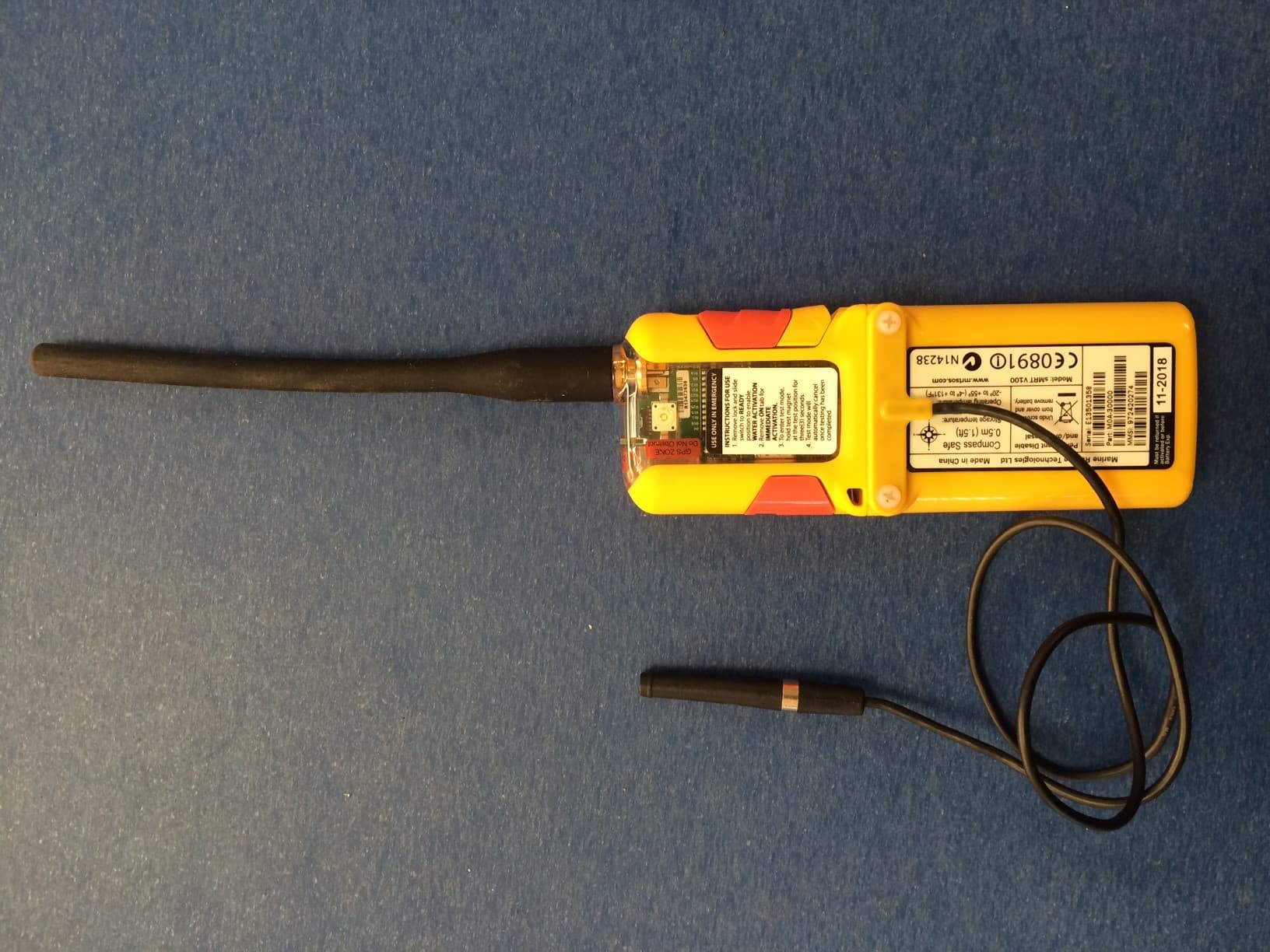
2AB4VSMRTV100
Feb 24, 2015Marine Survivor Locating Device MSLD
Equipment Class
AIS - Automatic Identification Systems