2AB4VSMRTV100Marine Survivor Locating Device MSLD
Marine Rescue Technologies Ltd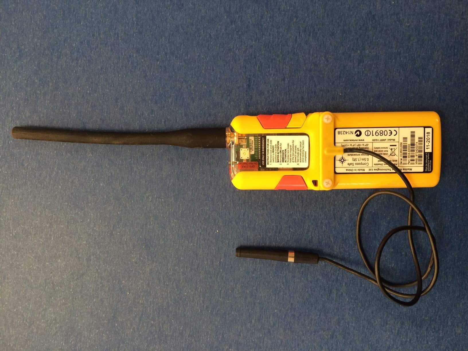
Click to zoom
Application Details
- Equipment Class
- AIS - Automatic Identification Systems
- Date of Grant
- Feb 24, 2015
- Application Purpose
- Original Equipment
- Date of Application
- Feb 24, 2015
- Equipment Note
- Marine Survivor Locating Device MSLD
- Frequency Range
- 161.97500000 - 162.02500000
- Country
- United Kingdom
Documents & Files
Document Text
Text extracted from the exhibit documents filed with the FCC. Open a document above to read the original.
Users Manual
790000022_sMRT V100 User Manual Version 2.0_20150112 January 2015 sMRT V100 User Manual sMRT V100 User Manual v2.0 MRT Ltd. © 2014 2 Table of Contents Part IIntroduction 3 Part IIGlossary of Terms & Acronyms 5 Part IIIWarnings & Safety Information 6 Part IVsMRT V100 Overview 8 1 .............................................................................. 10 sMRT V100 Features Part VsMRT V100 Operation 12 1 .............................................................................. 16 Cancelling Alerts 2 .............................................................................. 17 Testing Part VIRecertification and Servicing 20 Part VIIDeclaration of Conformity 22 Part VIIIWarranty 23 Part IXTerms of Sale 25 Part XDisclaimer 35 Part XITrademark Notice 36 Part XIITechnical Specifications 37 Index 38 MRT Ltd. © 2014 sMRT V100 User Manual v2.0 3 1Introduction This user manual provides all the information required to operate and test the sMRT V100. The following symbols and conventions are used to indicate important information. Always observe these instructions. Ensure you read the Warnings and Safety Information section of this manual before first use of the device. Warnings: Instructions that, if ignored, could result in death or serious personal injury caused by incorrect operation of the equipment. These must be observed for safe operation. Cautions: Instructions that, if ignored, could result in personal injury or material damage caused by incorrect operation of the equipment. These must be observed for safe operation. Important Note: Important instructions that should be adhered to during operation. Typographic Conventions 1. sMRT V100 hardware features are displayed in bold uppercase letters, e.g. SWITCH LOCK. 2. sMRT V100 operation states are displayed in bold uppercase letters surrounded by square brackets, e.g. [READY]. Using your sMRT V100 for the First Time Carefully read the Warnings and Safety Information section in this manual prior to using the sMRT V100 for the first time. To operate correctly, the sMRT V100 should be professionally fitted to an MRT approved PFD by a service centre authorised by MRT. Visit the MRT website www.mrtsos.com for specific instructions on accessing the sMRT V100. Prior to first use perform a full system test to confirm the device has been correctly programmed with your destination MMSI numbers. A device MMSI number is programmed into the unit at the factory and recorded on the label on the rear of the device. Destination MMSI 4 sMRT V100 User Manual v2.0 MRT Ltd. © 2014 numbers are also required for alerting vessels in your fleet during closed loop alerting sequences in an emergency. These numbers are programmed into VHF DSC radios on vessels in your fleet. They should be supplied to MRT, or an authorised service agent, in order to configure these destination MMSI numbers into each unit prior to being fitted into an MRT approved PFD. Warnings: DO NOT unzip the main PFD zip. Use the sMRT V100 access point zip in the life jacket to prepare the sMRT V100 for use. sMRT V100 Record of Ownership Manufacturers of man overboard devices maintain an ownership database in order to assist Search and Rescue (SAR) authorities in the event of an emergency. Registration of your product updates this database and is necessary to validate the device warranty. To register online, go to www.mrtsos.com and select ‘Product Registration’ from the Support menu. MRT Ltd. © 2014 sMRT V100 User Manual v2.0 5 2Glossary of Terms & Acronyms AISAutomatic Identification System: Automatic tracking system used on ships and by vessel traffic services for identifying and locating vessels by electronically exchanging data with other nearby ships, AIS base stations, and satellites. AMSAAustralian Maritime Safety Authority DSC Digital Selective Calling – technology used to automate calling on terrestrial marine radio systems. ECDISElectronic Chart Display and Information System EPIRBEmergency Position Indicating Radio Beacon. FCCUS Federal Communications Commission MAYDAYVoice distress priority message MMSIMaritime Mobile Service Identity (DSC identity number) MSLSMaritime Survivor Locating System mWUnit of power measurement; one thousandth of a Watt PFDPersonal Flotation Device PLDPersonal Locating Device RTCMRadio Technical Commission for Maritime Services SARSearch and Rescue USCGUS Coast Guard VHFVery High Frequency radio band – 30 to 300 MHz. WWatt - unit of electrical power measurement 6 sMRT V100 User Manual v2.0 MRT Ltd. © 2014 3Warnings & Safety Information WARNING: The sMRT V100 is not an EPIRB and its emergency transmission is not detected by orbiting satellites. The sMRT V100 is a short range Personal Locating Device (PLD), that transmits an emergency message via VHF DSC and AIS only. Before first use perform a full system test and confirm that the device has been correctly assigned with device and destination MMSI numbers. After deployment into active service, a regular full system test of the sMRT V100 should be performed every 3 months. Do not test the device more than once per month to avoid affecting battery performance in an emergency. The sMRT V100 should ONLY be used in an emergency. DELIBERATE MISUSE MAY INCUR A SEVERE PENALTY. The destination MMSI numbers of vessels in your fleet must be configured into the sMRT V100, or VHF DSC closed loop alerts will not be transmitted by the device during the first minutes of activation in an emergency. This could delay rescue and lead to loss of life. Annual inspection and recertification of the sMRT V100 by MRT Ltd. or an authorised service agent is required every 12 months. Do not dismantle the sMRT V100 as it contains no user- serviceable parts. MRT Ltd. and authorised service agents offer a full and comprehensive service and repair facility for recertification of units and battery replacement. The sMRT V100 emits radio frequency radiation when in use. Avoid handling the antenna when activated. The high intensity str…
Text truncated - open the document above for the full version.
Attestation Statements
Manufacturer and distributor of global leading Man Overboard Solutions from Marshall House l Zarya Court l Grovehill Road l Beverley l East Yorkshire l HU17 0JG l United Kingdom l Tel: +44 (0)1482 679300 l [email protected] l www.mrtsos.com Associated and accredited with: Vat number 772782395 l Company Registration Number 4202403 Certificate No. 8498 ISO 9001 Quality Management Sysyems Company Member 14 th January 2015 TIMCO Engineering Inc Product Testing and Certification RE FCC Part 80.203(b) Letter sMRTV100 FCCID 2AB4VSMRTV100 Dear Sir / Madam, The sMRTV100 product meets the requirement of the FCC rules, Part 80.203(b) Programming of the sMRTV100 transmit frequencies can only be performed by the manufacturer or by service personnel. It is not possible for the user to alter the transmit frequencies. Yours Sincerely, Colin Evans Direct: +44 (0) 1482 389863 Mobile: +44 (0) 7950 312810 Email: [email protected] Web: www.mrtsos.com
Operational Description
Manufacturer and distributor of global leading Man Overboard Solutions from Marshall House l Zarya Court l Grovehill Road l Beverley l East Yorkshire l HU17 0JG l United Kingdom l Tel: +44 (0)1482 679300 l [email protected] l www.mrtsos.com Associated and accredited with: Vat number 772782395 l Company Registration Number 4202403 Certificate No. 8498 ISO 9001 Quality Management Sysyems Company Member MARINE RESCUE TECHNOLOGIES LTD. - FCC ID: 2AB4VSMRTV100 - JOB #: 197AUT15/197BUT15 CIRCUIT DESCRIPTION: Turning ON the READY switch (SW4) will turn on the water sense circuit, which applies 1.8V to RSNS_HI via R45 (1M5 pull-up). When the unit is placed in salt water, current will conduct through the water to GND (at the VHF antenna connector) and the voltage level of RSNS_HI will be pulled low. If the water resistance is sufficiently low, RSNS_HI will be pulled below the negative-going threshold of the Schmitt trigger, causing it to output high. This switches on Q9 which, in turn, switches on Q6, applying power to the rest of the board. The microcontroller asserts POWER ON to hold ON Q6. This is independent of water being present or not. The RC circuit created by R45 and C38 also creates the intended feature that, when the user first switches the device into READY, the device will power on transiently (until R45 can pull RSNS_HI) allowing a POST to be performed. By the time POST is finished, RSNS_HI will have reached 1V8 (unless water is present), which the MCU can observe and, accordingly, de-assert the POWER_ON line (or activate, if water is present). The same RC circuit will filter any rapid changes to the resistance between RSNS HI and GND (the water). This, in tandem with the hysteresis of the Schmitt inverter, makes the water sense circuit very robust against spray and splash.
Parts List/Tune Up Info
Manufacturer and distributor of global leading Man Overboard Solutions from Marshall House l Zarya Court l Grovehill Road l Beverley l East Yorkshire l HU17 0JG l United Kingdom l Tel: +44 (0)1482 679300 l [email protected] l www.mrtsos.com Associated and accredited with: Vat number 772782395 l Company Registration Number 4202403 Certificate No. 8498 ISO 9001 Quality Management Sysyems Company Member 2 nd February 2015 Tuning Procedure: Maximum output power level during AIS transmission is 1 Watt +/- 500 mW. Maximum output power level during DSC transmission is 0.5 W +/- 250 mW. Yours Sincerely, Colin Evans.
RF Exposure Info
RF Exposure Evaluation Report APPLICANT MARINE RESCUE TECHNOLOGIES LTD. MARSHALL HOUSE 3 ZARYA COURT, GROVEHILL ROAD BEVERELY HU17 OJG FCC ID 2AB4VSMRTV100 MODEL NUMBER SMRTV100 PRODUCT DESCRIPTION MARITIME SURVIVOR LOCATING DEVICE STANDARD APPLIED CFR 47 Part 2.1091 PREPARED BY CORY LEVERETT We, TIMCO ENGINEERING, INC. would like to declare that the device has been evaluated in accordance with 47 CFR Part 2.1091 and meets the requirements. The attached report shall not be reproduced except in full without the written approval of TIMCO ENGINEERING, INC. 849 NW STATE ROAD 45 NEWBERRY, FL 32669 USA PH: 888.472.2424 OR 352.472.5500 FAX: 352.472.2030 EMAIL: [email protected] HTTP://WWW.TIMCOENGR.COM Applicant: MARINE RESCUE TECHNOLOGIES LTD. FCC ID: 2AB4VSMRTV100 Report: M\ MARINE RESCUE TECHNOLOGIES\197AUT15\197AUT15TestReport.docx Page 2 of 4 GENERAL REMARKS Attestations This equipment has been evaluated in accordance with the standards identified in this report. To the best of my knowledge and belief, these evaluations were performed using the procedures described in this report. I attest that the necessary evaluations were made, under my supervision, at: Timco Engineering Inc. 849 NW State Road 45 Newberry, Fl 32669 Authorized Signatory Name: Cory Leverett Engineering Project Manager Date: 2/20/2015 RF Exposure Requirements General information Device type: MARITIME SURVIVOR LOCATING DEVICE Devices that operate under Part 90 of this chapter are subject to RF exposure evaluation prior to equipment authorization or use. Antenna The manufacturer does not specify an antenna, but a typical antenna has a gain of 0 dBi. Configuration Antenna p/n Type Max. Gain (dBi) Fixed mounted Any omni 0 Operating configuration and exposure conditions: The conducted output power is shown in the table below. Typical use qualifies for a maximum duty cycle factor of 100%. Operation: A typical installation consists of an antenna system with a 10 meter coaxial cable of the type RG 213/ U type which has a loss as follows; Nom. Attenuation for RG 213/U: Frequency MHz Attenuation per 100ft. dB 1 .27 10 .55 50 1.3 100 1.9 200 2.7 400 4.1 700 6.5 900 7.6 1000 8.0 4000 21.5 MPE Calculation: The minimum separation distance is calculated as follows: Applicant: MARINE RESCUE TECHNOLOGIES LTD. FCC ID: 2AB4VSMRTV100 Report: M\ MARINE RESCUE TECHNOLOGIES\197AUT15\197AUT15TestReport.docx The limit for general uncontrolled exposure environment is shown in FCC rule Part 1.11310, Table 1. Max Power 1.2W equalsMax Power 1200 mW Duty Cycle 1 % equalsDuty Factor 0.01numeric Antenna Gain0 dBi equals Gain numeric1 numeric Coax Loss0 dB Gain - Coax Loss1 numeric Power Density 0.2 mW/cm 2 Frequency162.025 MHz Frequency rangPower denEnter this value MHz mW/cm 2 mW/cm 2 0.3-1.34100100 1.34-30 180/f 2 0.0 30-3000.20.2 300-1,500f/1500 0.1 1,500-100,00011 f = frequency in MHz Minimum Separation Distance2 cm0.02m Minimum Seperation in Inches 0.859617Inches Minimum Separation Distance for Mobile or Fixed Devices General Population/Uncontrolled Exposure Insert values in yellow highlighted boxes to determine Minimum Separation Distance Enter power Density from the chart to the rightRule Part 1.1310, Table 1
Test Report
HANDHELD MARINE RADIO PER FCC PT 80 TEST REPORT APPLICANT MARINE RESCUE TECHNOLOGIES LTD. ADDRESS MARSHALL HOUSE 3 ZARYA COURT, GROVEHILL ROAD BEVERELY HU17 OJG FCC ID 2AB4VSMRTV100 TESTED MODEL SMRTV100 PRODUCT DESCRIPTION SHORT RANGE PERSONAL LOCATING DEVICE DATE SAMPLE RECEIVED 1/26/2015 DATE TESTED 2/9/2015 TESTED BY Cory Leverett APPROVED BY Sid Sanders TEST RESULTS PASS FAIL Report Number Version Number Description Issue Date 197AUT15TestReport Rev.1 Initial Issue 2/20/2015 THE ATTACHED REPORT SHALL NOT BE REPRODUCED EXCEPT IN FULL WITHOUT THE WRITTEN APPROVAL OF TIMCO ENGINEERING, INC. 849 NW STATE ROAD 45 NEWBERRY, FL 32669 USA PH: 888.472.2424 OR 352.472.5500 FAX: 352.472.2030 EMAIL: [email protected] HTTP://WWW.TIMCOENGR.COM Applicant: MARINE RESCUE TECHNOLOGIES FCC ID: 2AB4VSMRTV100 Report: M\ MARINE RESCUE TECHNOLOGIES\197AUT15\197AUT15TestReport.docx Page 2 of 22 TABLE OF CONTENTS ATTESTATION ...................................................................................... 3 REPORT SUMMARY................................................................................ 4 TEST ENVIRONMENT AND TEST SETUP .................................................... 4 EUT DESCRIPTION ................................................................................ 5 TEST PROCEDURE ................................................................................ 6 TEST RESULTS SUMMARY ...................................................................... 5 RF POWER OUTPUT .......................................................................................................... 10 OCCUPIED BANDWIDTH ................................................................................................... 11 CONDUCTED UNWANTED EMISSIONS AT ANTENNA TERMINALS ..................................... 18 RADIATED UNWANTED EMISSIONS ................................................................................. 19 FREQUENCY STABILITY .................................................................................................... 20 TEST EQUIPMENT ............................................................................... 22 Applicant: MARINE RESCUE TECHNOLOGIES FCC ID: 2AB4VSMRTV100 Report: M\ MARINE RESCUE TECHNOLOGIES\197AUT15\197AUT15TestReport.docx Page 3 of 22 ATTESTATION This equipment has been tested in accordance with the standards identified in the referenced test report. To the best of my knowledge and belief, these tests were performed using the measurement procedures described in this report. The test results relate only to the items tested. All instrumentation and accessories used to test products for compliance to the indicated standards are calibrated regularly in accordance with ISO 17025: 2005 requirements. I attest that the necessary measurements were made by me or under my supervision, at Timco Engineering, Inc. located at 849 N.W. State Road 45, Newberry, Florida 32669 USA. Authorized by: Cory Leverett Signature: Function: Project Manager Date: 2/16/2015 Table of Contents Applicant: MARINE RESCUE TECHNOLOGIES FCC ID: 2AB4VSMRTV100 Report: M\ MARINE RESCUE TECHNOLOGIES\197AUT15\197AUT15TestReport.docx Page 4 of 22 REPORT SUMMARY Disclaimer The test results related only to the items tested. Purpose of Test To show the EUT in compliance with FCC CFR 47 Part 80 and Industry Canada RSS-182 requirements for handheld marine radio. Test Procedures ANSI/TIA 603-D: 2010, FCC CFR 47 Part 80, ANSI C63.4: 2003 Related Approval(s)/ Report(s) N/A TEST ENVIRONMENT AND TEST SETUP Test Facility All tests were conducted by: Timco Engineering Inc. 849 NW State Road 45, Newberry, FL 32669 USA Laboratory Test Condition Temperature: 26ºC Relative humidity: 50%. Deviation from the standards No deviation Modification to the EUT No physical modification was made. Software was used to manipulate the transmitter in the various test modes. Test Exercise (software etc.) sMRT V100 Programmer software, loads firmware into EUT System Setup No testing accessories. The EUT is a stand alone device. Table of Contents Applicant: MARINE RESCUE TECHNOLOGIES FCC ID: 2AB4VSMRTV100 Report: M\ MARINE RESCUE TECHNOLOGIES\197AUT15\197AUT15TestReport.docx Page 5 of 22 EUT DESCRIPTION Manufactured by MARINE RESCUE TECHNOLOGIES LTD. Product Description MARITIME SURVIVOR LOCATING DEVICE VHF Marine 156.025-157.425MHz FCC ID 2AB4VSMRTV100 M/N SMRTV100 Power Source 9 VDC Internal Battery Accessories IR programmer, Actisys IR Wireless Interface Test Item Preproduction Type of EUT Maritime Survivor Locating Device EUT Test Software Description Firmware Mode Functions Installed V150_RECEIVER_TEST.BIN Rx only V100_TEST V14.BIN Tx with and without modulation(Tester selectable) V100_APP V89.BIN Normal working mode TEST RESULTS SUMMARY FCC Rule Part Test RESULTS 80.209 Frequency Stability Pass 80.215 Power Output Pass 80.211 (d)(f) Unwanted Emissions Spectrum Mask Pass 80.211 (d)(f) Conducted Unwanted Emissions Pass 80.211 (d)(f) 15.209, 15.205 Radiated Unwanted Emissions Pass Table of Contents Applicant: MARINE RESCUE TECHNOLOGIES FCC ID: 2AB4VSMRTV100 Report: M\ MARINE RESCUE TECHNOLOGIES\197AUT15\197AUT15TestReport.docx Page 6 of 22 TECHNICAL SUMMARY FCC Rule Part IC Rule Part Item Description Pt 2.1033(c) (6) RSS-182 Operating Frequency 156.025 ~ 162.025 MHz Pt 80.205 (a) RSS-182 Occupied Bandwidth 16 kHz Pt 2.1033(c)(7) RSS-182 Power Range and Controls The EUT has a Fixed power level, no external controls are available Pt 2.1033(c)(8) RSS-182 DC Voltages and Current into Final Amplifier Not Applicable Pt 2.1046 Pt 80.215 (b)(2) RSS-182 Max. Output Pwr DSC: .42W AIS: 1.2 W Pt 80.205(a) Modulation FM Pt 80.271(a)(6) Antenna Socket SMA Pt 2.1033(c) Pt 80.205(a) (5) Type of Emissions G2B (DSC Channel), GXW (AIS Channels) Pt 80.203 (b) External Controls Not Applicable [Continued] Table of Contents Applicant: MARINE RESCUE TECHNOLOGIES FCC ID: 2AB4VSMRTV100 Report: M\ MARINE RESCUE TECHNOLOGIES\197AUT15\197AUT15TestReport.docx Page…
Text truncated - open the document above for the full version.
Test Report
grepbl.doc Ver: g01/10 "TRA-013792W US1.doc" A RADIO TEST REPORT FOR Marine Rescue Technologies Ltd ON sMRT V100 DOCUMENT NO. TRA-013792-W-US-1 Total number of pages : 88 Radio Test Report : TRA-013792W-US-1 Applicant : Marine Rescue Technologies Ltd Specification : RTCM STANDARD 11901.1 JUNE 4, 2012 Apparatus : sMRT V100 Authorised by : : Radio Product Manager Issue Date : 15 th April 2014 Authorised Copy Number : PDF RTCM STANDARD 11901.1 JUNE 4, 2012 TRaC Global Test Report: TRA-013792-W-US-1 3 Contents 1.1 General 5 1.2 Tests Requested By 6 1.3 Manufacturer 6 1.4 Apparatus Assessed 6 1.5 Equipment Test Conditions 7 1.6 Essential Radio Test Suite And Test Result Summary 8 1.7 Summary of Compliance 12 1.8 Notes Relating to the Assessment 12 1.9 Deviations from Test Standards 13 Section 2: Measurement Uncertainty 14 Section 3: Modifications 15 3.1 Modifications Performed During Assessment 15 Appendix A: General Requirements 16 A1 Function of the ON Control 17 A2 Alerting 18 Appendix B: DSC type MSLD 19 B1 DSC and AIS Combination MSLD Devices 20 B2 Alerting signal 21 B3 AU using DSC ‘all ships’ messages 22 B4 AU using DSC individual station relay messages 25 B5 Position Data 26 B6 Frequency and type of signal (Summary) 27 B7 Radiated power output 28 B8 Frequency error 29 B9 Carrier power 30 B10 Adjacent channel power 31 B11 Conducted spurious emissions conveyed to the antenna 32 B12 Cabinet radiation and conducted spurious emissions other than those conveyed to the antenna 33 B13 Transient frequency behavior of the transmitter 35 B14 Residual modulation of the transmitter 36 B15 Frequency error (demodulated DSC signal) 37 B16 Modulation index for DSC 38 B17 Modulation rate for DSC 39 B18 Testing of generated call sequences 40 Appendix C: AIS Type MSLD System 41 C1 Unique identifier (user ID) 42 C2 Battery 43 C3 Output Power 44 C4 Transmission performance - Active mode 45 C5 Transmission performance - Test mode 46 C6 Position Source and Data 47 C7 Channel 48 C8 Transmitter characteristics (Summary) 49 C9 Link layer requirements 50 C10 Synchronization method 51 C10 Synchronization accuracy 52 C10 VDL access scheme 53 RTCM STANDARD 11901.1 JUNE 4, 2012 TRaC Global Test Report: TRA-013792-W-US-1 4 C11 Frequency error 54 C12 Conducted power 56 C13 Radiated power 58 C14 Modulation spectrum slotted transmission 60 C15 Transmitter test sequence and modulation accuracy 61 C16 Transmitter output power versus time function 62 C17 Spurious emissions from the transmitter 63 C18 Tests for synchronization accuracy 64 C19 Active mode tests 65 C20 Test mode tests 69 Appendix D: Internal Navigation Device tests 71 Appendix E: Supporting Test Data 73 Message Data E8.1Appendix F: Additional Test and Sample Details 75 Appendix G: Additional Information 82 Appendix H: Photographs and Figures 82 RTCM STANDARD 11901.1 JUNE 4, 2012 TRaC Global Test Report: TRA-013792-W-US-1 5 Section 1: Introduction 1.1 General This report contains an assessment of an apparatus based upon tests carried out on samples submitted to the Laboratory. Test performed at: TRaC Global [ X ] Unit E South Orbital Trading Park Hedon Road Hull, HU9 1NJ. United Kingdom. Telephone: +44 (0) 1482 801801 Fax: +44 (0) 1482 801806 TRaC Global [ ] Unit 1 Pendle Place Skelmersdale West Lancashire, WN8 9PN United Kingdom Telephone: +44 (0) 1695 556666 Fax: +44 (0) 1695 577077 Email: [email protected] Web site: http://www.tracglobal.com Tests performed by: K J Anderson Author(s): K J Anderson This report must not be reproduced except in full without prior written permission from TRaC Global Ltd RTCM STANDARD 11901.1 JUNE 4, 2012 TRaC Global Test Report: TRA-013792-W-US-1 6 1.2 Tests Requested By This testing in this report was requested by : Marine Rescue Technologies Ltd Marshall House Zarya Court Grovehill Road Beverley East Yorkshire HU17 1JG United Kingdom 1.3 Manufacturer As above 1.4 Apparatus Assessed The following apparatus was assessed between sMRT V100 The EUT is a personal alerting and locating device for use in the marine environment. Integrated into a Personal Flotation Device, the sMRT V100 provides alerting via VHF DSC message and tracking via AIS to provide Search and Rescue forces an accurate location and identification of any casualty or casualties in the water following a Man Overboard incident. RTCM STANDARD 11901.1 JUNE 4, 2012 TRaC Global Test Report: TRA-013792-W-US-1 7 1.5 Equipment Test Conditions 1. Equipment Category: Category 1 (General) [ X ] Category 2 (Portable) [ ] Category 3 (Normal Indoor Use) [ ] 2. Temperatures: (see transmitter category) Tnom = (See test) Tmin = -25 o C [ X ] = -10 o C [ ] = 0 o C [ ] Tmax = +60 o C [ ] = +55 o C [X] = +40 o C [ ] = +30 o C [ ] 3. Transmitter Maximum Deviation or Shift: kHz = 7.4kHz 4. Transmitter Duty Cycle: % = 0.000134 5. Listen Before Talk: Yes = [ ] No = [ X ] 6. Channel Spacing: kHz = N/A Narrowband [ ] Wideband [X] 7. Receiver Class: Class = 2 RTCM STANDARD 11901.1 JUNE 4, 2012 TRaC Global Test Report: TRA-013792-W-US-1 8 1.6 Essential Radio Test Suite And Test Result Summary Full details of test results are contained within Appendix A, B, C and D. The following table summarises the results of the assessment. The statements relating to compliance with the standards below apply ONLY as qualified in the notes and deviations stated in sections 1.7 to 1.9 of this test report. This report contains an assessment of an apparatus against RTCM STANDARD 11901.1 JUNE 4, 2012, based upon tests carried out on samples submitted to the Laboratory. Test Type Reference clause in RTCM STANDARD 11901.1 JUNE 4, 2012 Appendix no in this report Mod no. Result Function of the ON control 4.1.3 A1 0 Pass Alerting 4.1.4.1 A2 0 Pass RTCM STANDARD 11901.1 JUNE 4, 2012 TRaC Global Test Report: TRA-013792-W-US-1 9 Test Type Reference clause in RTCM STANDARD 11901.1 JUNE 4, 2012 Appendix no in this report Mod no. Result DSC and AIS Combination MSLD Devices A.3.5 B1 0 Pass Alerting signal A.3.6 B2 0 Pass …
Text truncated - open the document above for the full version.
Test Report
WARWICK Rothwell Road, Warwick, CV34 5JX, UK. T +44 (0)1926 478478 F +44(0)1926 478479 E [email protected] www.tracglobal.com Certificate of Testing N o : TRA021534CC01A Page 1 of 4 Pages Test Engineer Approval P. Bullock Test Technician D. K. Morris Chief Test Engineer Certified that the specimens detailed hereon have been subjected to the tests as required by the order unless otherwise stated above. Our technical competence and quality control arrangements are in accordance with the conditions of our UKAS accreditation. No representation or warranty is given that the Tests performed under the terms of Contract constitute, in themselves, a sufficient programme for the Customer’s purpose, nor that the Customer’s Equipment is suitable for any particular purpose. The contents of this Certificate shall not be reproduced, except in full, without the written approval of TRaC Global Limited. Marine Rescue Technologies Ltd Marshall House Zarya Court Grovehill Road Beverley East Yorkshire HU17 1JG Issue Date: 27 th May 2014 Our Ref: TRA-021534-00 Client’s Order Number: PO 01417 Date of Tests: 6 th and 7 th May 2014 Attn.: Jon Gething Specimen(s): 1 Off sMRT V100 Software Version: MOA-30000 Serial Number: E13500671 TRaC Stores Number: TRA-021534-S1 Receipt Date: 01/05/2014 1 Off sMRT V100 Software Version: MOA-30000 Serial Number: E13500531 TRaC Stores Number: TRA-021534-S2 Receipt Date: 07/05/2014 Specification: Testing was carried out in accordance with BS EN 60529:1992 and TRaC Global Limited quotation TRA-021534-00 dated 23 rd April 2014. IP6X - Dust Tight Testing in accordance with BS EN 60529:1992. Test Duration: 80 Volumes of the specimen, or 8 hours; whichever is achieved first. Vacuum: ≤ -20mbar Certificate of Testing N o : TRA021534CC01A Page 2 of 4 Pages Specification (cont.): IPX7 – Temporary Immersion in Water Water Level: 1 metre above lowest point of enclosure Duration: 30 minutes Configuration: Non-Operational. Procedure: IP6X - Dust Tight The specimen TRA-021534-S1 was found to have no openings that could be penetrated by the access probe of 1 mm ø. The specimen was connected to a vacuum pump, pressure indicator and flow meter to calculate the test duration. The specimen was mounted in the dust chamber and re-connected to the vacuum pump to provide a gauge vacuum to laboratory ambient pressure during the test. The test was carried out in accordance with the specification for a period of 4.66 hours, the vacuum and flow stabilised at 0.04 l/min at -3mbar, Figure 1. IPX7 – Temporary Immersion in Water The temperature of the specimen TRA-021534-S2 and the water temperature were checked to ensure the differential was within 5ºC. The specimen was secured in its normal working orientation and then immersed in laboratory ambient temperature tap water, Figure 2, to a depth of 1.0m to the lowest surface of the specimen, for a period of 30 minutes. Results: IP6X - Dust Tight After testing the specimen was cleaned externally before being opened for internal inspection. No dust ingress was found. IPX7 – Temporary Immersion in Water After testing, the specimen was removed from the water, Figure 3, and dried externally before being opened for internal inspection. No water ingress was found. An example of an inspection is shown in Figure 4. The specimen TRA-021534-S1 therefore satisfies the requirements of BS EN 60529: 1992 IP6X. The specimen TRA-021534-S2 therefore satisfies the requirements of BS EN 60529: 1992 IPX7. Certificate of Testing N o : TRA021534CC01A Page 3 of 4 Pages SPECIMEN TRA-021534-S1 AFTER UNDERGOING IP6X DUST TEST FIGURE 1 SPECIMEN TRA-021534-S2 SECURED TO A WEIGHTED FRAME FOR IPX7 IMMERSION F IGURE 2 Certificate of Testing N o : TRA021534CC01A Page 4 of 4 Pages SPECIMEN TRA-021534-S2 REMOVED FROM WATER FOR INSPECTION FIGURE 3 SPECIMEN TRA-021534-S2 INSPECTED FOR WATER INGRESS FIGURE 4
Test Setup Photos
197AUT14 Test Setup Photo’s Applicant: MARINE RESCUE TECHNOLOGIES FCC ID: 2AB4VSMRTV100 Report: M\MARINE RESCUE TECHNOLOGIES\197AUT15\197AUT15TestReport.docx
Contact Information
Applicant
Colin Evans
Technical Contact
Timco Engineering, Inc.Cory Leverett
[email protected]888-472-2424
849 NW State Road 45 · Newberry, Florida · United States
Non-Technical Contact
Timco Engineering, Inc.Sharon Hoffman
[email protected]888-472-2424
Test Firm
Timco Engineering, Inc.Bruno Clavier
Technical Specifications
| # | Rule Parts | Frequency Range | Power Output | Emission | Tolerance |
|---|---|---|---|---|---|
| 2 | 8 | 161.975 MHz - 162.025 MHz | 1.2 W | 16K0GXW | 0.91 ppm |
Other Applications from Marine Rescue Technologies Ltd
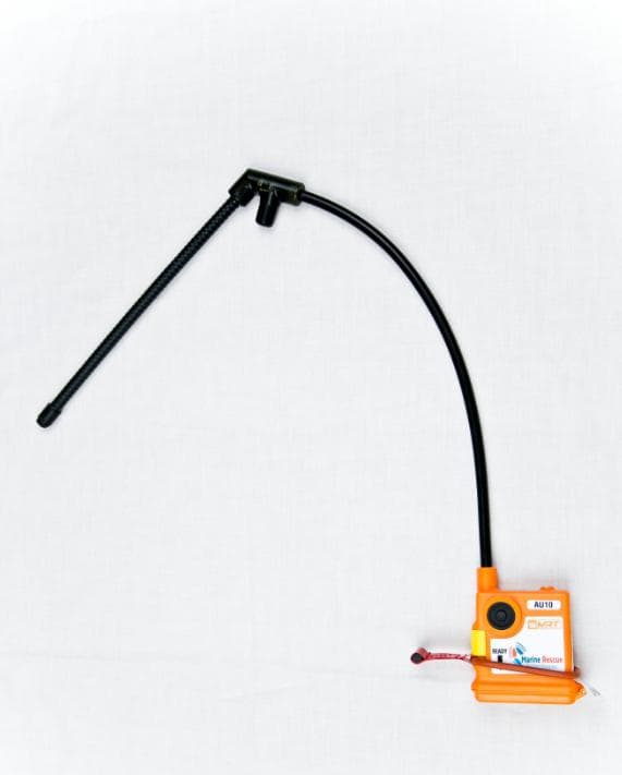
2AB4VAU10
Jun 19, 2014sMRT AU10 EMERGENCY PERSONAL LOCATOR DEVICE WITH AIS
Equipment Class
PLB - Personal Locator Beacons