2AB4XAMP10524TSPY TRACKER
Atomic Monkey Products Ltd.Application Details
- Equipment Class
- DXX - Part 15 Low Power Communication Device Transmitter
- Date of Grant
- May 28, 2015
- Application Purpose
- Original Equipment
- Date of Application
- May 28, 2015
- Equipment Note
- SPY TRACKER
- Frequency Range
- 2412.00000000 - 2472.00000000
- Company
- Atomic Monkey Products Ltd.
- Country
- Hong Kong
Documents & Files
Document Text
Text extracted from the exhibit documents filed with the FCC. Open a document above to read the original.
Users Manual
Ages 6 and up 10524 SpyX Spy Tracker Requires Six AAA (LR03), not included. Important: Please save this instruction sheet. It contains valuable product information. How to Track Movement up to 75 feet (22.86m) away! 1. Turn on the alarm base by moving the switch (Fig 1.) to the "ON" position 2. Turn on each transmitter pod by moving the switch on the side of the pod to the "ON" position (Fig 1.) 3. Place each transmitter pod in a location where you expect movement to occur (hallway, kitchen counter, etc.). Position the pod's top arrow (silver color) pointed in the direction of movement. The pod's motion sensor must not be covered to allow it to trigger the base alarm. Note each pod has a number (pod #1 or pod #2). Remember where each pod is located! 4. Take the base alarm unit with you anywhere within 75 feet (22.86 m) of the pod location and watch carefully to see if sensor 1 or sensor 2 alarm activates! The correct LED light will blink on the alarm base when there is any movement in front of the transmitter pod. Hint: You can place pod #1 further away from you and Pod #2 closer to you so you can track movement to see if it is coming toward you or going away from you! Hint: You can also move the alarm switch (located near bottom of the alarm base unit) either to the silent mode ( ) if you only want a blinking light, or move it to the loudspeaker mode ( ) if you want an audible alarm to warn you of movement in front of the pod. Tip: When finished playing with the Spy Tracker please turn off the transmitter pods and alarm base to save battery life! To store or carry the transmitter pods on the pod holder loop (Fig 2.) Locate the end of the loop where it attaches to the base. To remove the end of the loop from the base, Rotate the ball-end downwards so that it can pull straight out from the socket. When the end is detached you can string each pod onto the loop for carrying or safekeeping. Close the loop by placing the ball-end back into the socket and rotating upwards into the locked position. BATTERY SAFETY INFORMATION · Only adults should install and replace batteries. · Do not recharge non-rechargeable batteries. · Remove dead or exhausted batteries. · Insert batteries correctly. Match positive and negative signs. · The supply terminals are not to be short circuited. · Do not use rechargeable batteries. · Do not mix alkaline, standard (carbon-zinc), or rechargeable (nickel-cadmium) batteries. · Do not mix old and new batteries. · Only the batteries of the same or equivalent type recommended to be used. · Do not dispose of batteries in a fire; they may explode. · Dispose of batteries safely. SPYX SPY TRACKER 10524-4000 Product specifications subject to change. IF YOU HAVE ANY QUESTIONS, PLEASE CONTACT US AT www.atomicmonkeyproducts.com/help © 2015 Atomic Monkey Products, Ltd. Hong Kong, China, All rights reserved. PRINTED IN CHINA FCC INFO AREA FCC INFO AREA AAA AAA AAA AAA Power On/Off Power On/Off Power On/Off Fig 1. Fig 3. Fig 2. Belt Clip Battery Cover Alarm Base Sensor Alarm #1 Sensor Alarm #2 Silent / Loudspeaker Switch Transmitter Pod #1 Transmitter Pod #2 Belt Clip Release Tab Battery Cover Pod Holder Loop Socket Ball End SPY TRACKER ™ Mobile Early-Warning system! ATTENTION ADULTS—TO INSTALL AND REPLACE BATTERIES SpyX Spy Tracker. Base alarm requires two AAA (LR03) batteries, not included. Each transmitter pod receiver requires two AAA (LR03) batteries, not included (a total of four AAA batteries for both pods). • Locate the belt clip on the bottom of the base alarm. To gain access to the battery cover, press the release tab on the belt clip and slide the belt clip toward the bottom end of the alarm base unit • Locate the battery door on the back of each transmitter pod and the alarm base (Fig. 3) • Use a small Phillips head screwdriver to loosen the screw, and remove the battery cover (Fig.3). • Remove all old batteries. • Place new batteries in compartments as shown (Fig. 3). • Replace the battery covers and tighten screw and replace belt clip on alarm base. EU Compliance : This device complies with EU EMF Directive 1999/519/EC can be used in the European Community. “ Hereby, (Atomic Monkey Products Ltd.), declares that this device is in compliance with the essential requirements and other relevant provisions of Directive 1999/5/EC.” FCC Statement: This device complies with part 15 of the FCC Rules. Operation is subject to the following two conditions:(1)This device may not cause harmful interference, and (2) this device must accept any interference received, including interference that may cause undesired operation. Any Changes or modifications not expressly approved by the party responsible for compliance could void the user's authority to operate the equipment. Note: This equipment has been tested and found to comply with the limits for a Class B digital device, pursuant to part 15 of the FCC Rules. These limits are designed to provide reasonable protection against harmful interference in a residential installation. This equipment generates, uses and can radiate radio frequency energy and, if not installed and used in accordance with the instructions, may cause harmful interference to radio communications. However, there is no guarantee that interference will not occur in a particular installation. If this equipment does cause harmful interference to radio or television reception, which can be determined by turning the equipment off and on, the user is encouraged to try to correct the interference by one or more of the following measures: -Reorient or relocate the receiving antenna. -Increase the separation between the equipment and receiver. -Connect the equipment into an outlet on a circuit different from that to which the receiver is connected. -Consult the dealer or an experienced radio/TV technician for help. SAR Exemption Statement : This device measured RF output power is less than the SAR exclusion threshold value for human head and body. Therefore, SAR test is not n…
Text truncated - open the document above for the full version.
Test Report
RF Exposure evaluation According to 447498 D01 General RF Exposure Guidance v05 The 1-g and 10-g SAR test exclusion thresholds for 100 MHz to 6 GHz at test separation distances≤ 50 mm are determined by: [(max. power of channel, including tune-up tolerance, mW)/(min. test separation distance, mm)] ·[√f(GHz)] ≤ 3.0 for 1-g SAR and ≤ 7.5 for 10-g extremity SAR, where f(GHz) is the RF channel transmit frequency in GHz Power and distance are rounded to the nearest mW and mm before calculation The result is rounded to one decimal place for comparison eirp = pt x gt = (EXd)2/30 where: pt = transmitter output power in watts, gt = numeric gain of the transmitting antenna (unitless), E = electric field strength in V/m, --- 10((dBuV/m)/20)/106 d = measurement distance in meters (m)---3m Sopt = (EXd)2/30 x gt Ant gain 1.5dBi ;so Ant numeric gain=1.41 Field strength = 71.75dBuV/m @3m So Pt={ [10( 71.75 /20 )/10 6 x3] 2 /30x1.41 }x1000 mW =0.03mW So ( 0.03mW/5mm)x √2.440GHz =0.001< 3 Then SAR evaluation is not required
Test Setup Photos
Radiated Emission Test Set-up: Below 1GHz: Above 1GHz:
Contact Information
Applicant
Wilson Mak
Technical Contact
ECMG Electronic Technical Testing Corp.(Shenzhen)Jawen Yin
Room 305-306,3F,Building A,No.30 Hangkong Road · Shenzhen · China
Test Firm
CCIC-SETQi Zhu
Technical Specifications
| # | Rule Parts | Frequency Range | Power Output |
|---|---|---|---|
| 1 | 15C | 2.41 GHz - 2.47 GHz | - |
Other Applications from Atomic Monkey Products Ltd.
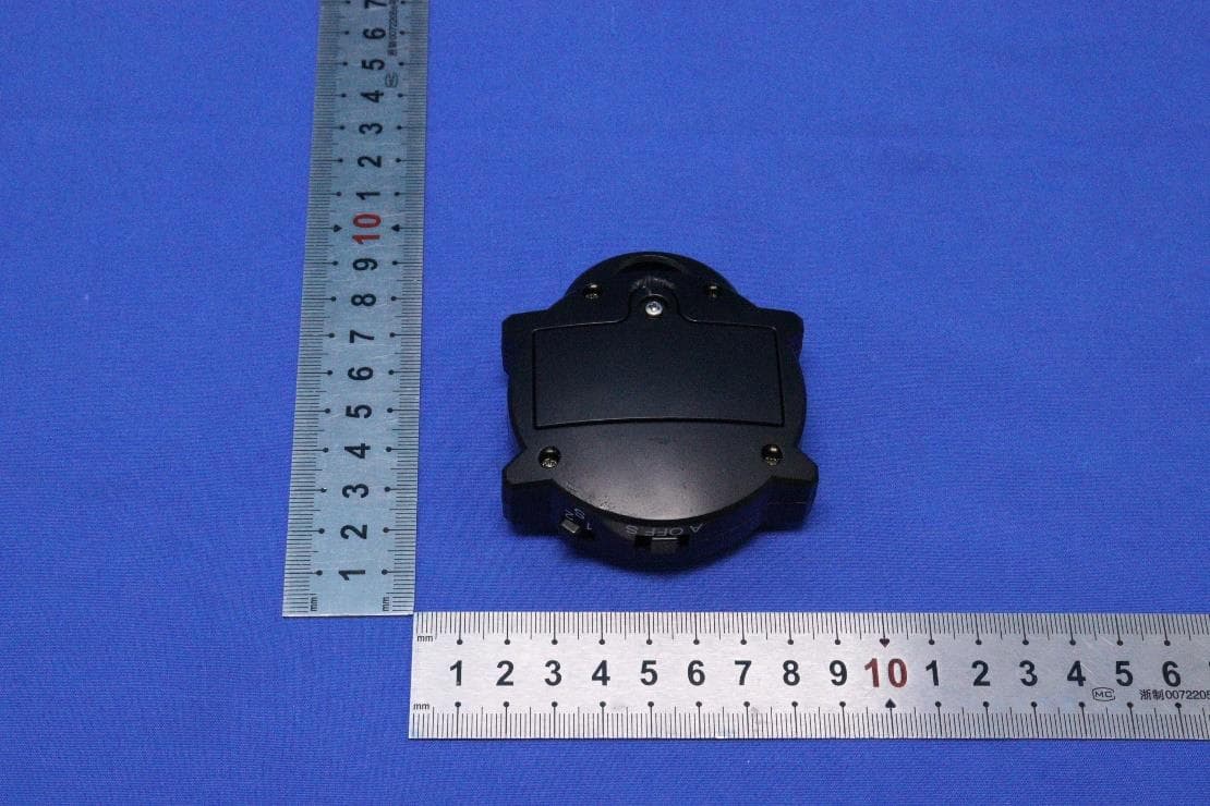
2AB4XAMP10534R
Jun 26, 2023TRACKER TAG
Equipment Class
DXX - Part 15 Low Power Communication Device Transmitter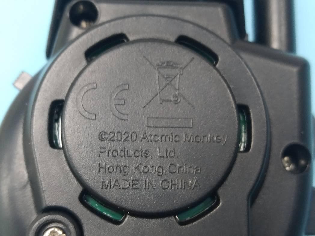
2AB4XAMP10538
Jun 21, 2020Spy Wrist Talkies
Equipment Class
DXX - Part 15 Low Power Communication Device Transmitter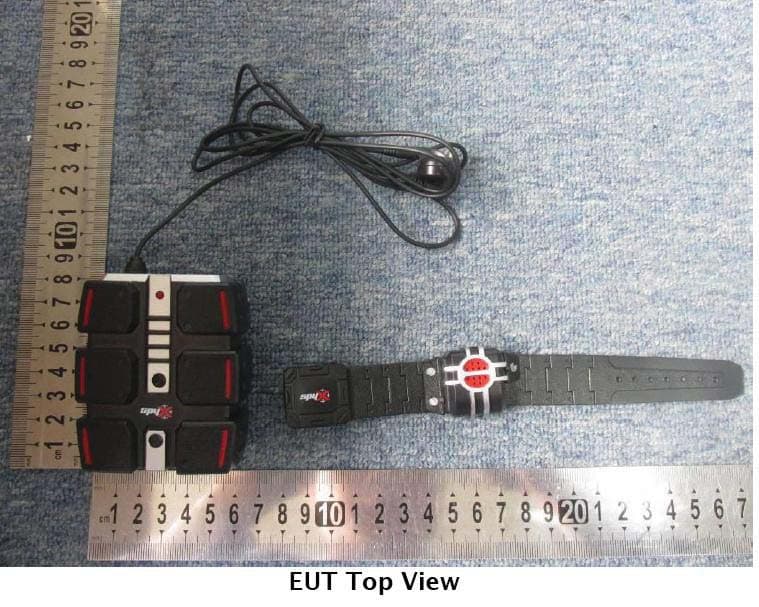
2AB4XAMP10522
May 29, 2015SECRET AGENT WALKIE TALKIES
Equipment Class
DXX - Part 15 Low Power Communication Device Transmitter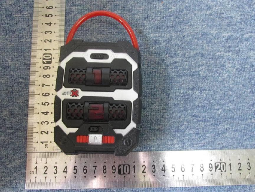
2AB4XAMP10524R
May 29, 2015SPY TRACKER
Equipment Class
DXX - Part 15 Low Power Communication Device Transmitter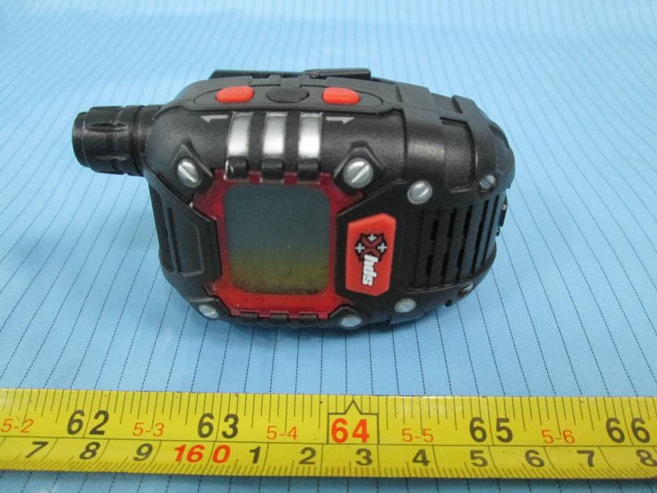
2AB4XAMP10520
Jun 11, 2014Long Range Wrist Talkies
Equipment Class
FRF - Part 95 Family Radio Face Held Transmitter