2AB5RBAD221BLE Mesh network device
SwipeSense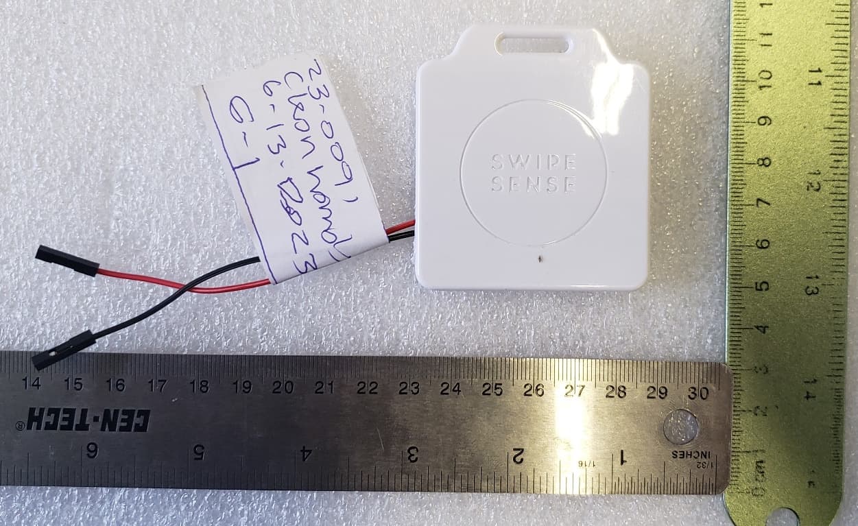
Click to zoom
Application Details
- Equipment Class
- DTS - Digital Transmission System
- Date of Grant
- Jul 10, 2023
- Application Purpose
- Original Equipment
- Date of Application
- Jul 10, 2023
- Equipment Note
- BLE Mesh network device
- Frequency Range
- 2402.00000000 - 2480.00000000
- Company
- SwipeSense
- Country
- United States
Documents & Files
Document Text
Text extracted from the exhibit documents filed with the FCC. Open a document above to read the original.
Users Manual
SwipeSense, Inc. 4424 N Ravenswood Ave. Chicago, IL. 60640 (847) 440-6215 Asset Tag User Manual Asset Tag Model: 221.0Page 1 of 4 June 2023 SwipeSense, Inc. 4424 N Ravenswood Ave. Chicago, IL. 60640 (847) 440-6215 Safety and Regulatory Information This device complies with part 15 of the FCC Rules. Operation is subject to the following two conditions. (1) this device may not cause harmful interference, and (2) this device must accept any interference received, including interference that may cause undesired operation. Warning:Changes or modifications not expressly approved by the party responsible for compliance could void the user’s authority to operate the equipment This equipment has been tested and found to comply with the limits for a Class B digital device, pursuant to part 15 of the FCC Rules. These limits are designed to provide reasonable protection against harmful interference in a residential installation. This equipment generates, uses and can radiate radio frequency energy and, if not installed and used in accordance with the instructions, may cause harmful interference to radio communications. However, there is no guarantee that interference will not occur in a particular installation. If this equipment does cause harmful interference to radio or television reception, which can be determined by turning the equipment off and on, the user is encouraged to try to correct the interference by one or more of the following measures: Reorient or relocate the receiving antenna. Increase the separation between the equipment and receiver. Connect the equipment into an outlet on a circuit different from that to which the receiver is connected. Consult the dealer or an experienced radio/ TV technician for help. This device must not be co-located with other transmitters. RF Exposure: This equipment complies with FCC RF Exposure requirements and should be installed and operated with a minimum distance of 20cm between the radiator and any part of the human body. WarningsThis Device is for indoor use only. This Device is only to be installed by trained SwipeSense personnel. Do not open the Device as there are no user serviceable parts inside and this product is powered at all times. Do not use if the case is cracked or worn. CautionChanges or modifications not expressly approved by the party responsible for compliance could void the user’s authority to operate the equipment. Asset Tag Model: 221.0Page 2 of 4 June 2023 SwipeSense, Inc. 4424 N Ravenswood Ave. Chicago, IL. 60640 (847) 440-6215 System Description The SwipeSense System combines point-of-care hand hygiene with real-time usage data to eliminate dependency on manual observations and increase compliance with infection control procedures. Our fully integrated system seamlessly provides real-time hand hygiene data from across the enterprise with exceptional clarity. The SwipeSense System creates a “mesh network” that provides flexibility for compiling and communicating hygiene practices of employees within your facility. The mesh network is comprised of: Badges worn on individual employees Asset tags attached to assets that should be tracked Hygiene sensors mounted to hygiene dispensers tracks employee hand sanitation frequency Entry sensors installed in door thresholds to provide real time feedback Location hubs monitor employee presence in patient rooms and asset locations Communication hub located on each unit collects the data generated within the network and transmits to the cloud. Once the data is uploaded to the cloud, it is accessible to all administrators. Asset Tag Model: 221.0Page 3 of 4 June 2023 SwipeSense, Inc. 4424 N Ravenswood Ave. Chicago, IL. 60640 (847) 440-6215 Product Description This is a small device that should be attached to any asset that needs to be tracked. This device transmits signals to the Location Hubs allowing them to establish their location. A picture of the SwipeSense Asset Tag attached to a Phillips Intellivue MX40 as an example is provided in Figure 1. Figure 1: Asset Tag Installation Procedure 1.If the Asset Tag is not pre-assigned to a specific asset, assign the Device ID in the App associating the Asset Tag with the asset. 2.Attach the Asset Tag to the asset that needs to be tracked using zip ties, or some other non- permanent method of attachment. Asset Tag Model: 221.0Page 4 of 4 June 2023
Attestation Statements
221 221
Attestation Statements
3505 Francis Circle Alpharetta, GA 30004 PH: 770-740-0717 www.ustech-lab.com SDoC Attestation Letter Date: June 21, 2023 Subject: SDoC Attestation Letter: FCC ID: 2AB5RBAD221 The following equipment meets FCC Part 15 SDoC Requirements for digital device: Responsible Party: SwipeSense, Inc. 4424 N. Ravenswood Ave. Chicago, IL 60640 – United States Jeremy Jass Principal Hardware Architect 404-2424-0855 Email: [email protected] Equipment: Model Name: Asset Tag Sincerely, By: __________________________ George Yang __- Agent (Signature/Title) (Print name)
Cover Letter(s)
6/30/2023
Cover Letter(s)
Request for Confidentiality Date: June 21, 2023_____ Subject: Confidentiality Request for: ___FCC ID: 2AB5RBAD221 Pursuant to FCC 47 CRF 0.457(d) and 0.459, the applicant requests that a part of the subject FCC application be held confidential. Type of Confidentiality Requested Exhibit Short Term Permanent Block Diagrams Short Term External Photos Short Term Permanent Internal Photos Short Term Permanent Operation Description/Theory of Operation Short Term Permanent Parts List & Placement/BOM Short Term Permanent Tune-Up Procedure Short Term Permanent Schematics Short Term Test Setup Photos Short Term Permanent* User’s Manual SwipeSense, Inc. has spent substantial effort in developing this product and it is one of the first of its kind in industry. Having the subject information easily available to "competition" would negate the advantage they have achieved by developing this product. Not protecting the details of the design will result in financial hardship. Permanent Confidentiality: The applicant requests the exhibits listed above as permanently confidential be permanently withheld from public review due to materials that contain trade secrets and proprietary information not customarily released to the public. Sincerely, By: __________________________ ___George Yang __- Agent (Signature/Title) (Print name)
External Photos
US Tech Test Report: FCC Part 15 Certification FCC ID: 2AB5RBAD221 Test Report Number: 23-0091 Issue Date: June 21, 2023 Customer: SwipeSense, Inc. Model: Asset Tag Page 1 of 5 EXTERNAL PHOTOGRAPHS Figure 1. Top of EUT Note: Cables coming out of EUT are for external power and programming for intentional radio testing. US Tech Test Report: FCC Part 15 Certification FCC ID: 2AB5RBAD221 Test Report Number: 23-0091 Issue Date: June 21, 2023 Customer: SwipeSense, Inc. Model: Asset Tag Page 2 of 5 Figure 2. Back of EUT US Tech Test Report: FCC Part 15 Certification FCC ID: 2AB5RBAD221 Test Report Number: 23-0091 Issue Date: June 21, 2023 Customer: SwipeSense, Inc. Model: Asset Tag Page 3 of 5 Figure 3. Left Side of EUT Figure 4. Right Side of EUT US Tech Test Report: FCC Part 15 Certification FCC ID: 2AB5RBAD221 Test Report Number: 23-0091 Issue Date: June 21, 2023 Customer: SwipeSense, Inc. Model: Asset Tag Page 4 of 5 Figure 5. Front of EUT US Tech Test Report: FCC Part 15 Certification FCC ID: 2AB5RBAD221 Test Report Number: 23-0091 Issue Date: June 21, 2023 Customer: SwipeSense, Inc. Model: Asset Tag Page 5 of 5 Figure 6. Bottom of EUT
ID Label/Location Info
221.0 Asset Tag FCC Label Information Notes: •FCC ID text is 1.0mm tall •FCC ID:...” line will be updated to “FCC ID: 2A5BRBAD221” "MODEL:" line will be updated to "BAD221" B5
Internal Photos
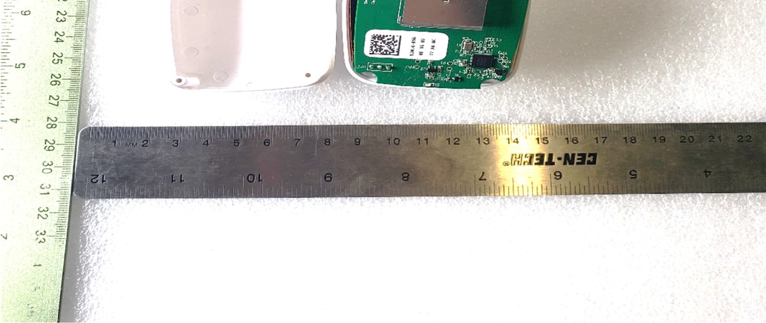
US Tech Test Report: FCC Part 15 Certification FCC ID: 2AB5RBAD221 Test Report Number: 23-0081 Issue Date: June 21, 2023 Customer: SwipeSense, Inc. Model: Asset Tag Page 1 of 4 INTERNAL PHOTOGRAPHS Figure 1. EUT, Front Cover Removed US Tech Test Report: FCC Part 15 Certification FCC ID: 2AB5RBAD221 Test Report Number: 23-0081 Issue Date: June 21, 2023 Customer: SwipeSense, Inc. Model: Asset Tag Page 2 of 4 Figure 2. Back of Main PCB US Tech Test Report: FCC Part 15 Certification FCC ID: 2AB5RBAD221 Test Report Number: 23-0081 Issue Date: June 21, 2023 Customer: SwipeSense, Inc. Model: Asset Tag Page 3 of 4 Figure 3. Front of Main PCB US Tech Test Report: FCC Part 15 Certification FCC ID: 2AB5RBAD221 Test Report Number: 23-0081 Issue Date: June 21, 2023 Customer: SwipeSense, Inc. Model: Asset Tag Page 4 of 4 Figure 4. Enclosure with Main PCB Removed
RF Exposure Info
US Tech Test Report: FCC Part 15 Certification FCC ID: 2AB5RBAD221 Test Report Number: 23-0091 Issue Date: June 21, 2023 Customer: SwipeSense, Inc. Model: Asset Tag Page 1 of 1 Maximum Public Exposure to RF (MPE) CFR 15.247 (i), CFR 1.1310 (e) The maximum exposure level to the public from the RF power of the EUT shall not exceed a power density, S as per the respective limits in Table 1 below, at a distance, d, of 20 cm (Mobile condition) from the EUT. TABLE 1—LIMITS FOR MAXIMUM PERMISSIBLE EXPOSURE (MPE) Frequency range (MHz) Electric field strength (V/m) Magnetic field strength (A/m) Power density (mW/cm 2 ) Averaging time (minutes) Limits for General Population/Uncontrolled Exposure 0.3-1.34 614 1.63 *100 30 1.34-30 824/f 2.19/f *180/f 2 30 30-300 27.5 0.073 0.2 30 300-1,500 f/1500 30 1,500-100,000 1.0 30 f = frequency in MHz * = Plane-wave equivalent power density Therefore, for: MPE for 2400 MHz – 2483.5 MHz for Bluetooth LE: Limit: 1.0 mW/cm 2 Peak Power (dBm) = 0.99 dBm Peak Power (Watts) = 0.001 W Gain of Transmit Antenna = +2.01dB i =1.59 numeric (Highest Gain Antenna) d = Distance = 20 cm = 0.2 m S = (PG/ 4π ππ πd 2 ) = EIRP/4A = 0.001(1.59)/4*π*0.2*0.2 = 0.00159/0.5030 = 0.00316 W/m 2 = (0.00316 W/m 2 ) (1m 2 /W) (0.1 mW/cm 2 ) = 0.000316 mW/cm 2 which is << less than S = 1.0 mW/cm 2
Test Report
US Tech Test Report: FCC Part 15 Certification FCC ID: 2AB5RBAD221 Test Report Number: 23-0085 Issue Date: June 21, 2023 Customer: SwipeSense, Inc. Model: Asset Tag Page 1 of 2 Antenna Test Report Inverted F-Trace Antenna Figure 1. EUT antenna design Table 1. Measured Field Strength from Test Report Test: FCC Part 15,247(d), Test Distance= 3 m Frequency (MHz) Test Data (dBuV) Additional Factor AF+CL-PA (dB/m) Corrected Results (dBuV/m) Limits (dBuV/m) Distance / Polarization Margin (dB) Detector Low Channel - PEAK 2402.00 68.42 0.00 32.35 100.77 -- 3.0m./HORZ -- PK Mid Channel – PEAK 2442.00 68.30 0.00 32.55 100.85 -- 3.0m./VERT -- PK High Channel– PEAK 2480.00 66.30 0.00 32.81 99.11 -- 3.0m./VERT -- PK US Tech Test Report: FCC Part 15 Certification FCC ID: 2AB5RBAD221 Test Report Number: 23-0085 Issue Date: June 21, 2023 Customer: SwipeSense, Inc. Model: Asset Tag Page 2 of 2 Antenna gain calculated using the following equations to convert the measured field strength value to V/m. dBuV/m to V/m = 10^([dBuV/m] – 120) 20 Table 2. Converted Fundamental to V/m Frequency of Fundamental (MHz) V/m 2402 0.109 2442 0.110 2480 0.090 Table 3. Measured Conducted Output Power from Test Report Frequency of Fundamental (MHz) Raw Test Data dBm Converted Data (mW) 2402 0.99 1.26 2442 0.77 1.19 2480 0.66 1.16 Gain numeric = (Meters * V/m) 2 /(30*Watts) Watts = measured conducted output power from Table 3 above. Gain numeric to Gain dBi = 10^(Gain numeric/10) Table 4. Antenna Gain Frequency of Fundamental (MHz) Gain Numeric Gain dBi Peak Antenna Gain dBi 2402 2.828 1.91 2.01 2442 3.050 2.01 2480 2.094 1.61
Test Report
Page 1 of 49 Application For Part 2, Subpart J, Paragraph 2.907 Equipment Authorization of Certification for an Intentional Radiator per Part 15, Subpart C Intentional Radiator, paragraphs 15.207, 15.209 and 15.247 Operation within the bands 902–928 MHz, 2400–2483.5 MHz, and 5725–5850 MHz. For the SwipeSense, Inc. Model Number: Asset Tag FCC ID: 2AB5RBAD221 UST Project: 23-0091 Issue Date: June 21, 2023 Total Pages: 49 3505 Francis Circle Alpharetta, GA 30004 PH: 770-740-0717 Fax: 770-740-1508 www.ustech-lab.com Page 2 of 49 I certify that I am authorized to sign for the Test Agency and that all of the statements in this report and in the Exhibits attached hereto are true and correct to the best of my knowledge and belief: US TECH (Agent Responsible For Test): By: Alan Ghasiani Name: Title: Compliance Engineer – President Date: June 21, 2023 This report shall not be reproduced except in full. This report may be copied in part only with the prior written approval of US Tech. The results contained in this report are subject to the adequacy and representative character of the sample provided. This report must not be used to claim product certification, approval, or endorsement by NVLAP, NIST or any agency of the Federal Government. 3505 Francis Circle Alpharetta, GA 30004 PH: 770-740-0717 Fax: 770-740-1508 www.ustech-lab.com US Tech Test Report: FCC Part 15 Certification FCC ID: 2AB5RBAD221 Test Report Number: 23-0091 Issue Date: June 21, 2023 Customer: SwipeSense, Inc. Model: Asset Tag Page 3 of 49 MEASUREMENT TECHNICAL REPORT COMPANY NAME: SwipeSense, Inc. ADDRESS: 4424 N. Ravenswood Ave. Chicago, IL 60640 USA MODEL: Asset Tag FCC ID: 2AB5RBAD221 DATE: June 21, 2023 This report concerns (check one): ☒Original grant □Class II change Equipment type: 2.4 GHz BLE transmitter Device Technical: BLE 2402 MHz - 2480 MHz (Channels 0-39) Type of modulation: GFSK Data/Bit Rate: 1 MBPS Antenna Gain: +2.01dBi (Trace Antenna) Maximum Output Power: +0.99 dBm Software used to program EUT: Nordic Microcontroller - nrfjprog EUT firmware number: version 1.0 Power setting: Maximum level Report prepared by: US Tech 3505 Francis Circle Alpharetta, GA30004 US Tech Test Report: FCC Part 15 Certification FCC ID: 2AB5RBAD221 Test Report Number: 23-0091 Issue Date: June 21, 2023 Customer: SwipeSense, Inc. Model: Asset Tag Page 4 of 49 Table of Contents Paragraph Title Page 1 General Information .......................................................................................... 7 1.1 Purpose of this Report .................................................................................. 7 1.2 Characterization of Test Sample ................................................................... 7 1.3 Product Description ...................................................................................... 7 1.4 Configuration of Tested System .................................................................... 8 1.5 Test Facility ................................................................................................... 8 1.6 Related Submittal(s)/Grant(s) ....................................................................... 8 2 Tests and Measurements ............................................................................... 10 2.1 Test Equipment ........................................................................................... 10 2.2 Modifications to EUT Hardware .................................................................. 11 2.3 Number of Measurements for Intentional Radiators (15.31(m)) .................. 11 2.4 Frequency Range of Radiated Measurements (Part 15.33)........................ 12 2.4.1 Intentional Radiator .................................................................................. 12 2.4.2 Unintentional Radiator ............................................................................. 12 2.5 Measurement Detector Function and Bandwidth (CFR 15.35) ................... 12 2.5.1 Detector Function and Associated Bandwidth ......................................... 12 2.5.2 Corresponding Peak and Average Requirements .................................... 12 2.6 EUT Antenna Requirements (CFR 15.203) ................................................ 13 2.7 Restricted Bands of Operation (Part 15.205) .............................................. 14 2.8 Transmitter Duty Cycle (Part15.35 (c)) ....................................................... 14 2.9 Antenna Conducted Intentional and Spurious Emissions (CFR 15.209, 15.247(d)) ............................................................................................................. 14 2.10 Intentional Radiator, Radiated Emissions (CFR 15.209, 15.247(d)) ........ 21 2.11 Band Edge Measurements (CFR 15.247(d)) ........................................... 24 2.12 Six (6) dB Bandwidth (CFR 15.247(a)(2)) ................................................ 31 2.13 Maximum Peak Conducted Output Power (CFR 15.247 (b) (3)) ............. 35 2.14 Intentional Radiator Power Lines Conducted Emissions (CFR 15.207) ... 43 2.15 Intentional Radiator, Radiated Emissions (CFR 15.209) ......................... 44 2.16 Measurement Uncertainty ....................................................................... 49 2.16.1 Conducted Emissions Measurement Uncertainty .................................. 49 2.16.2 Radiated Emissions Measurement Uncertainty ..................................... 49 3 Conclusions .................................................................................................... 49 US Tech Test Report: FCC Part 15 Certification FCC ID: 2AB5RBAD221 Test Report Number: 23-0091 Issue Date: June 21, 2023 Customer: SwipeSense, Inc. Model: Asset Tag Page 5 of 49 List of Figures Figures Title Page Figure 1. Block Diagram of Test Configuration ........................................................ 13 Figure 2. Channel 0, 30-1000 MHz .......................................................................... 15 Figure 3. …
Text truncated - open the document above for the full version.
Test Setup Photos
US Tech Test Report: FCC Part 15 Certification FCC ID: 2AB5RBAD221 Test Report Number: 23-0091 Issue Date: June 21, 2023 Customer: SwipeSense, Inc. Model: Asset Tag Page 1 of 6 TEST CONFIGURATION PHOTOGRAPHS Figure 1. Radiated Emissions Test Setup US Tech Test Report: FCC Part 15 Certification FCC ID: 2AB5RBAD221 Test Report Number: 23-0091 Issue Date: June 21, 2023 Customer: SwipeSense, Inc. Model: Asset Tag Page 2 of 6 Figure 2. Radiated Emissions Test Setup, .15 MHz to 30 MHz US Tech Test Report: FCC Part 15 Certification FCC ID: 2AB5RBAD221 Test Report Number: 23-0091 Issue Date: June 21, 2023 Customer: SwipeSense, Inc. Model: Asset Tag Page 3 of 6 Figure 3. Radiated Emissions Test Setup, 30 MHz to 200 MHz US Tech Test Report: FCC Part 15 Certification FCC ID: 2AB5RBAD221 Test Report Number: 23-0091 Issue Date: June 21, 2023 Customer: SwipeSense, Inc. Model: Asset Tag Page 4 of 6 Figure 4. Radiated Emissions Test Setup, 200 MHz to 1GHz US Tech Test Report: FCC Part 15 Certification FCC ID: 2AB5RBAD221 Test Report Number: 23-0091 Issue Date: June 21, 2023 Customer: SwipeSense, Inc. Model: Asset Tag Page 5 of 6 Figure 5. Radiated Emission Test Setup, above 1 GHz US Tech Test Report: FCC Part 15 Certification FCC ID: 2AB5RBAD221 Test Report Number: 23-0091 Issue Date: June 21, 2023 Customer: SwipeSense, Inc. Model: Asset Tag Page 6 of 6 Figure 6. Bench Test Setup
Contact Information
Applicant
Jeremy Jass
Test Firm
US TechGeorge Yang
Technical Specifications
| # | Rule Parts | Frequency Range | Power Output |
|---|---|---|---|
| 1 | 15C | 2.40 GHz - 2.48 GHz | 1.00 mW |
Other Applications from SwipeSense
2AB5RHUB521
Jul 10, 2023Location Sensor for BLE Mesh network
Equipment Class
DTS - Digital Transmission System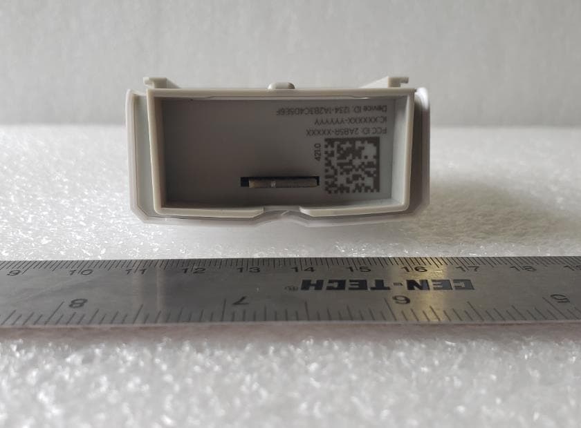
2AB5RSEN421
Jul 10, 2023BLE 2.4 GHz Sensor device used with BLE Mesh network
Equipment Class
DTS - Digital Transmission System
2AB5RCOM621
Jul 10, 2023BLE 2.4 GHz Communication Hub
Equipment Class
DTS - Digital Transmission System
2AB5RMOD001
Jun 30, 2015SwipeSense Wireless module
Equipment Class
DXX - Part 15 Low Power Communication Device Transmitter
2AB5RHUB001
Jul 20, 2014Room Hub
Equipment Class
DXX - Part 15 Low Power Communication Device Transmitter