2AB7X-CHB2CToast Chipper 2X BT
BBPOS Limited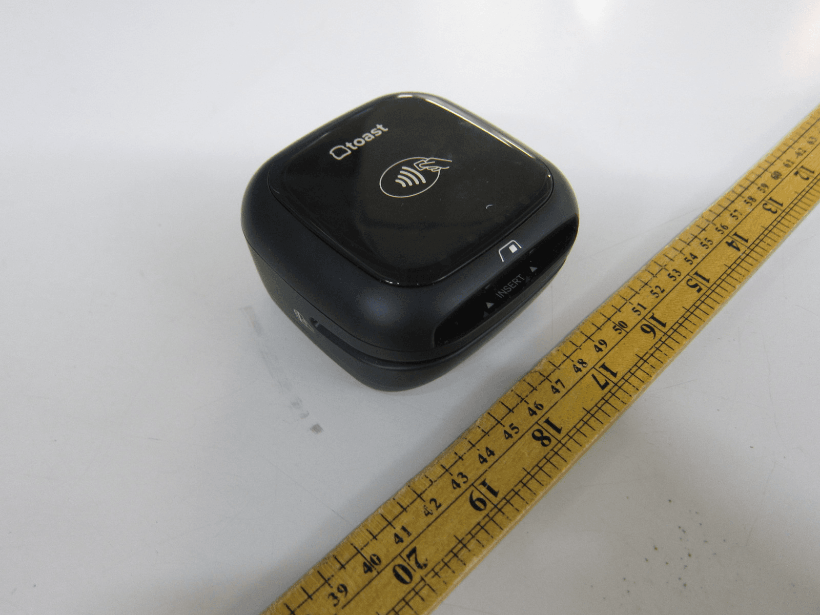
Click to zoom
Application Details
- Equipment Class
- DXX - Part 15 Low Power Communication Device Transmitter
- Date of Grant
- Jun 26, 2021
- Application Purpose
- Original Equipment
- Date of Application
- Jun 26, 2021
- Equipment Note
- Toast Chipper 2X BT
- Frequency Range
- 13.56000000 - 13.56000000
- Company
- BBPOS Limited
- Country
- Hong Kong
Documents & Files
Document Text
Text extracted from the exhibit documents filed with the FCC. Open a document above to read the original.
Users Manual
Contactless Pay INSTALLATION & CONFIGURATION INSTRUCTIONS WHAT’S IN THE BOX? Note: You will only use one of the cables provided to install your contactless reader. Contactless Puck Contactless Reader Plate with adhesive Stickers for your door or windows to advertise the types of payments you can accept USB-A to Micro-USB cable Counter placement pad for your Contactless Puck Tool kit containing a screwdriver, alcohol wipes, and extra adhesives ! Micro-USB to Micro-USB cable 4 3 2 1 5 6 7 1 2 3 4 5 6 7 Wipe down the countertop with the alcohol wipe provided in your tool kit. This will make it even easier for your contactless puck to adhere properly. Next, if you have an existing card reader, physically remove it before installation. You’ll also need to digitally remove the reader in Toast following these steps: 1. Navigate to the main menu on your terminal, then select Device Setup. 2. Select the card reader, then select the red Remove Card Reader option. Reader ready! Processing Success! Error Insert chip cards with chip facing up. Swipe with stripe facing up (only for cards without chip or if chip fails). Here’s a breakdown of your new hardware. Below explains each light and both ways to insert or slide cards. 1 YOUR NEW CONTACTLESS PUCK ASSESS YOUR COUNTER SPACE AND TERMINAL 2 Begin by determining the cable you’ll use to plug in your contactless reader. You’ll only use one of these cables. This cable plugs into the USB port on your device. See installation instructions for the USB-A to Micro-USB cable on the next page. USB-A to Micro-USB cable We recommend using this cable if you have an available port open on your Toast Hub, USB-Hub, or Toast Printer. PICK YOUR CABLE FOR INSTALLATION Micro-USB to Micro-USB cable This cable with the plate attached plugs into the side of your terminal and is adhered with screws. Jump ahead to the Micro-USB to Micro-USB installation instructions. If you don’t have an available port, or if you only have a terminal, use this cable instead. OR 1. Take the USB-A end of the cable and plug it into your Toast Hub or USB-Hub. Or plug the USB end of the cable into your Toast Printer. USB – A TO MICRO - USB INSTALL STEPS 2. Plug in the remaining Micro-USB side into the bottom of the puck. Nice work! Next, turn to the EMV Configuration section to enable all types of payments. The end of this cable will be marked “to reader.” 1. Remove the plate covering the port on the side of your terminal. 3. If your terminal stand has a neck to hide the cable, feed it through for a cleaner look. 4. Plug in the remaining end into the bottom of the puck. MICRO - USB TO MICRO - USB INSTALL STEPS 2. Plug in the end of the Micro-USB cable paired with the cover and screws. Then screw in the plate to the terminal. Nice work! Turn to the next page to enable EMV so your reader can accept all types of payment. The end of this cable will be marked “to reader.” 3 EMV CONFIGURATION Your contactless reader will auto detect once plugged into your Toast system. You’ll need to enable EMV for the ability to take chip card and contactless payments. 4. You’ll see an option for Card Readers below the EMV settings. Your new contactless puck is listed as: BBPOS Chipper 2X(USB) Confirm this is listed. You may also be prompted to update the reader’s software. If so, opt into the update. If you have a second screen attached to your terminal - also known as a guest-facing display - you may have an additional swipe-only card reader. If you have this, make sure the BBPOS Chipper 2X(USB) reader is set to Guest Pay. ! Note: Switching out readers automatically turns the EMV setting off. Even if you’ve already enabled it, EMV will need to be turned on again. 1. Once the puck has been properly plugged into your Toast hardware, restart your terminal. 2. From the main menu in Toast, select Device Setup. 3. In the list of settings, there will be an option EMV Enabled. Make sure that this is turned on. 4 2. To anchor your contactless puck, take the plate with adhesive and apply it to your counter surface. FINISHING TOUCHES 1. Wrap your cable around the inside of your puck in a clockwise motion to reduce wire clutter. ! Keep in mind, the adhesive is strong, so plan your anchoring spot wisely. 3. Firmly press the plate down with the adhesive and hold for six seconds. The “insert” side should face toward your guests. The reader can sit on the plate, but can be removed to fit any scenario. This side up “Insert” side Back FINISHING TOUCHES Cards can be: • Tapped on the top of the puck. • Dipped into the front slot with the card chip facing up. • Swiped across in any direction with the card stripe facing upwards. Note: If you were using a card reader with dip options prior, you’ll need to reconfigure your manager swipe cards. ! Questions? See the Contactless Reader Troubleshooting Guide. Or contact Toast Support online or via phone at 617-682-0225. Set up for success with Training & Best Practices. Scan the QR code with the camera app on your phone to access these documents for more info! Let your customers know they can pay with contactless. Find a visible clean spot on the counter to display the card reader and mat. 2. 1. 3. 4. Place on the surface in your preferred location. Place Toast puck device in the space provided. Flip mat over to preferred color treatment. toast-pay-instructional.indd 18/30/19 9:14 AM U ser shall use the supplied USB cable if an available port open on the product
Cover Letter(s)
BBPOS International Limited Suite 1903-04, 19/F, Tower 2, Nina Tower, No. 8 Yeung Uk Road, Tsuen Wan, N.T., Hong Kong 香港新界荃灣楊屋道8號如心廣場2期19樓1903-04室 Tel 電話 (852) 3158-2585 Fax 傳真 (852) 3158-2586 www.bbpos.com Letter of Agency for FCC Certification 24 May 2021 To whom it may concern, Letter of Agency I, an officer of BBPOS International Limited do hereby authorize Intertek Testing Services (Mr. Terry Chan / Tim Lee / Herbert Wong / Kenneth Wong) to act on our behalf in front of the Federal Communications Commission with respect to all matters relating to certification of equipment under Part 15 and Part 18 of the FCC Rules until further notice." I further certify that no party (as defined in §1.2002(b) of CFR 47, 2004) to this application, including myself, is subject to a denial of federal benefits, that includes FCC benefits, pursuant to Section 5301 of the Anti-Drug Abuse Act of 1988, 21 U.S.C.,862. Regards, Adrian Kwan Product Compliance Manager
Cover Letter(s)
BBPOS International Limited Suite 1903-04, 19/F, Tower 2, Nina Tower, No. 8 Yeung Uk Road, Tsuen Wan, N.T., Hong Kong 香港新界荃灣楊屋道8號如心廣場2期19樓1903-04室 Tel 電話 (852) 3158-2585 Fax 傳真 (852) 3158-2586 www.bbpos.com Page 1 of 2 24 May 2021 Attention: Application Examiner Re: Request for confidentiality Applicant: BBPOS International Limited FCC ID: 2AB7X-CHB2B and 2AB7X-CHB2C and 2AB7X-CHB2D To whom it may concern, Request for Permanent Confidentiality under FCC Part 15 Certification Request is hereby submitted by BBPOS International Limited to withhold permanently from public review certain portions of the application for equipment certification for the referenced FCC identifiers. This request for confidentiality is made pursuant to 47 CFR 0.457(d) & 0.459 of the FCC Rules. In particular, the following sections of the application are to be kept permanently confidential: Schematics Detailed Block diagrams Detailed Operational/Functional Description Rationale for request for confidentiality: This information represents intellectual property of BBPOS International Limited and it is subject to competition. We have invested considerable time and materials in research and development to produce the referenced product. Disclosure of the permanently confidential portions of this application to competitors would not only give them significant competitive advantages in developing similar products, but would also disclose successful implementation of unpublished, leading edge technology developed by us. BBPOS International Limited Suite 1903-04, 19/F, Tower 2, Nina Tower, No. 8 Yeung Uk Road, Tsuen Wan, N.T., Hong Kong 香港新界荃灣楊屋道8號如心廣場2期19樓1903-04室 Tel 電話 (852) 3158-2585 Fax 傳真 (852) 3158-2586 www.bbpos.com Page 2 of 2 BBPOS International Limited has invested considerable time and materials in research and development to produce the referenced product. Disclosure of the permanently confidential portions of this application to competitors would not only give them significant competitive advantages in developing similar products, but would also disclose successful implementation of unpublished, leading edge technology developed by us. If you have questions or need further information, please contact the undersigned. Regards, Adrian Kwan Product Compliance Manager
External Photos
INTERTEK TESTING SERVICE Report No.: HK21050718 Equipment Photographs (External)
Internal Photos
INTERTEK TESTING SERVICE Report No.: HK21050718 Equipment Photographs (Internal) INTERTEK TESTING SERVICE Report No.: HK21050718 Equipment Photographs (Internal) INTERTEK TESTING SERVICE Report No.: HK21050718 Equipment Photographs (Internal) INTERTEK TESTING SERVICE Report No.: HK21050718 Equipment Photographs (Internal) INTERTEK TESTING SERVICE Report No.: HK21050718 Equipment Photographs (Internal) INTERTEK TESTING SERVICE Report No.: HK21050718 Equipment Photographs (Internal) INTERTEK TESTING SERVICE Report No.: HK21050718 Equipment Photographs (Internal)
RF Exposure Info
INTERTEK TESTING SERVICE FCC ID: 2AB7X-CHB2C MPE Analysis Report The Equipment Under Test (EUT) is a Toast Chipper 2X BT which is a POS device (point of sale device). It supports reading magnetic stripe credit card, EMV smart credit card and passive RFID tag credit card. It can be connected to PC via USB port and operated by a corresponding software. The magnetic head is for reading data from credit card tape swiping. The embedded EMV chip interface are used for reading EMV smart credit card data. The EUT contains 13.56MHz NFC tag reader for contactless payment card transaction. The EUT is powered by USB port (5VDC). NFC Portion (13.56MHz single channel) Antenna Type: Internal, Integral Antenna Gain: 0dBi Maximum conducted RF power: 0dBm Maximum allowed production tolerance: +0dB / -40dB . For Maximum Permissible Exposure (MPE) evaluation of the unit, the maximum power density at 20 cm from this transmitter shall be less than the General Population / Uncontrolled MPE limit in OET Bulletin 65 and meet the requirement listed in KDB447498. For the NFC portion of the EUT, the measured powers among all the measured channels were within its production tolerance. The antenna gain is 0 dBi = 1 (num gain) and its maximum source-based time-averaging duty factor is 100%. From these data and its operating configuration, the exposed power density at a distance (R) of 20cm from the center of radiation of the antenna can be calculated according to OET Bulletin 65 as follow: The EIRP radiated power = conducted power (with maximum tolerance) + antenna gain = 0 dBm + 0 dBi = 0 dBm (1 mW) The radiated (EIRP) source-based time-averaging output power = (1 * 1) mW = 1 mW The power density at 20 cm from the antenna = EIRP / 4 πR^2 = 0.0002 mW cm-2
Test Report
2/F., Garment Centre, 576 Castle Peak Road, Kowloon, Hong Kong SAR, China. Telephone: (852) 2173 8888 Facsimile: (852) 2785 5487 www.intertek.com Intertek’s standard Terms and Conditions can be obtained at our website http://www.intertek.com/terms/. The test report only allows to be revised within the retention period unless further standard or the requirement was noticed. This report is for the exclusive use of Intertek's Client and is provided pursuant to the agreement between Intertek and its Client. Intertek's responsibility and liability are limited to the terms and conditions of the agreement. Intertek assumes no liability to any party, other than to the Client in accordance with the agreement, for any loss, expense or damage occasioned by the use of this report. Only the Client is authorized to permit copying or distribution of this report and then only in its entirety. Any use of the Intertek name or one of its marks for the sale or advertisement of the tested material, product or service must first be approved in writing by Intertek. The observations and test results in this report are relevant only to the sample tested. This report by itself does not imply that the material, product, or service is or has ever been under an Intertek certification program. © 2017 Intertek Page 1 of 22 TEST REPORT Report No.: 21050718HKG-002 BBPOS International Limited Application For Certification (Original Grant) FCC ID: 2AB7X-CHB2C Transceiver Prepared and Checked by: Approved by: Signed On File Wong Cheuk Ho, Herbert Lead Engineer Wong Kwok Yeung, Kenneth Senior Lead Engineer Date: June 16, 2021 TEST REPORT BBPOS International Limited Intertek Report No: 21050718HKG-002 Page 2 of 22 GENERAL INFORMATION Grantee: BBPOS International Limited Grantee Address: Suite 1903-04, 19/F., Tower 2, Nina Tower, No. 8 Yeung Uk Road, Tsuen Wan, N.T., Hong Kong. Contact Person: Adrian Kwan Tel: +852 3158 2585 Fax: +852 3158 2586 e-mail: [email protected] Manufacturer: BBPOS International Limited Manufacturer Address: Suite 1903-04, 19/F., Tower 2, Nina Tower, No. 8 Yeung Uk Road, Tsuen Wan, N.T., Hong Kong. Brand Name: Toast Model : CHB2C Type of EUT: Transceiver Description of EUT: Toast Chipper 2X BT Serial Number: N/A FCC ID: 2AB7X-CHB2C Date of Sample Submitted: May 12, 2021 Date of Test: May 12, 2021 to June 08, 2021 Report No.: 21050718HKG-002 Report Date: June 16, 2021 Environmental Conditions: Temperature: +10 to 40°C Humidity: 10 to 90% Conclusion: Test was conducted by client submitted sample. The submitted sample as received complied with the 47 CFR Part 15 Certification. TEST REPORT BBPOS International Limited Intertek Report No: 21050718HKG-002 Page 3 of 22 SUMMARY OF TEST RESULT Test Specification Reference Results Transmitter Field Strength Frequency Stability 15.225 Pass Radiated Emission Radiated Emission on the Bandedge 15.209 Pass Radiated Emission in Restricted Bands 15.205 Pass The equipment under test is found to be complying with the following standards: FCC Part 15, October 1, 2019 Edition Note: 1. The EUT uses a permanently attached antenna which, in accordance to section 15.203, is considered sufficient to comply with the pervisions of this section. 2. Pursuant to FCC part 15 Section 15.215(c), the 20 dB bandwidth of the emission was contained within the frequency band designated (mentioned as above) which the EUT operated. The effects, if any, from frequency sweeping, frequency hopping, other modulation techniques and frequency stability over excepted variations in temperature and supply voltage were considered. TEST REPORT BBPOS International Limited Intertek Report No: 21050718HKG-002 Page 4 of 22 TABLE OF CONTENTS 1.0 GENERAL DESCRIPTION ........................................................................................................... 5 1.1 Product Description ............................................................................................................. 5 1.2 Related Submittal(s) Grants ................................................................................................. 5 1.3 Test Methodology ................................................................................................................ 5 1.4 Test Facility .......................................................................................................................... 5 2.0 SYSTEM TEST CONFIGURATION ............................................................................................... 6 2.1 Justification .......................................................................................................................... 6 2.2 EUT Exercising Software ....................................................................................................... 6 2.3 Special Accessories ............................................................................................................... 6 2.4 Measurement Uncertainty ................................................................................................... 6 2.5 Support Equipment List and Description .............................................................................. 6 3.0 EMISSION RESULTS ................................................................................................................. 7 3.1 Field Strength Calculation .................................................................................................... 7 3.2 Radiated Emission Configuration Photograph ...................................................................... 8 3.3 Radiated Emission Data ........................................................................................................ 8 3.4 Conducted Emission Configuration Photograph ................................................................... 8 3.5 Conducted Emission Data .................................................................................................... 8 3.6 Frequency Stability ...............................…
Text truncated - open the document above for the full version.
Test Setup Photos
INTERTEK TESTING SERVICE Report No: HK21050718 i Configuration Photographs Worst-Case Line-Conducted Emissions (Front View) INTERTEK TESTING SERVICE Report No: HK21050718 ii Configuration Photographs Worst-Case Line-Conducted Emissions (Rear View) INTERTEK TESTING SERVICE Report No: HK21050718 iii Configuration Photographs Worst-Case Line-Conducted Emissions (Side View)
Test Setup Photos
INTERTEK TESTING SERVICE Report No: HK21050717 Configuration Photographs Worst-Case Radiated Emissions (Front View) INTERTEK TESTING SERVICE Report No: HK21050717 Configuration Photographs Worst-Case Radiated Emissions (Rear View)
Contact Information
Applicant
Adrian Kwan
Technical Contact
Intertek Testing Services Hong Kong LtdKenneth Wong
[email protected]852-39126902
2/F Garment Centre · Hong Kong · China
Non-Technical Contact
Intertek Testing Services Hong Kong LtdKenneth Wong
[email protected]852-39126902
Test Firm
Intertek Testing Services Hong Kong Ltd.Billy Chow
Technical Specifications
| # | Rule Parts | Frequency Range | Power Output |
|---|---|---|---|
| 1 | 15C | 13.56 MHz - 13.56 MHz | - |
Other Applications from BBPOS Limited
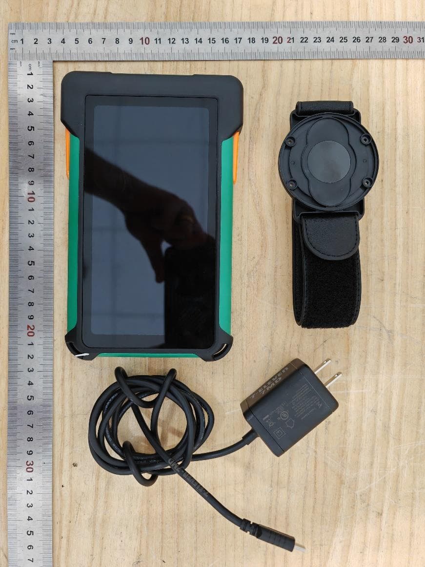
2AB7X-WSP7V1
Sep 22, 2024WisePOS Pro, 7MD
Equipment Class
DSS - Part 15 Spread Spectrum Transmitter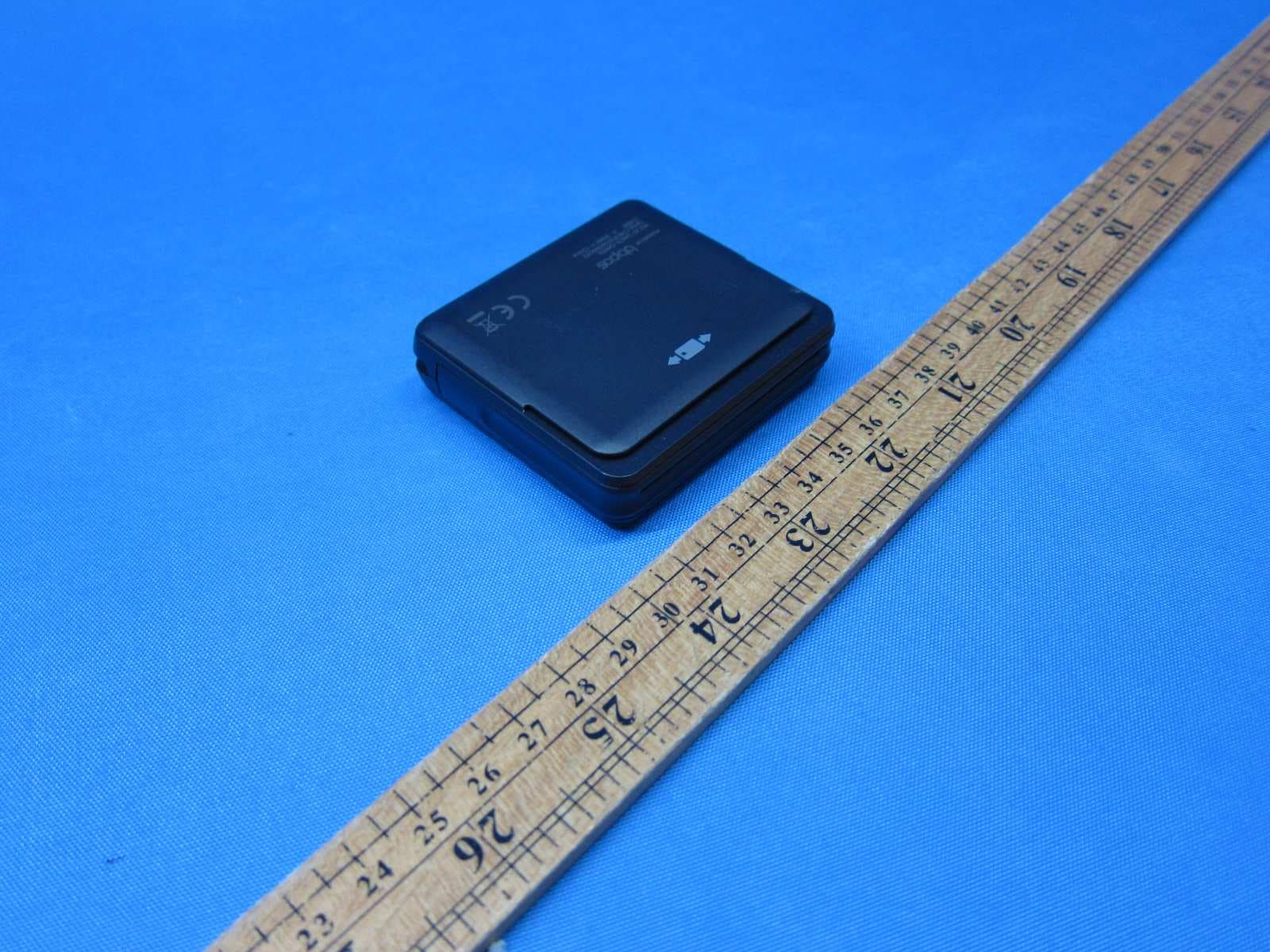
2AB7X-CHB2F
Nov 27, 2021Chipper 2X BT
Equipment Class
DXX - Part 15 Low Power Communication Device Transmitter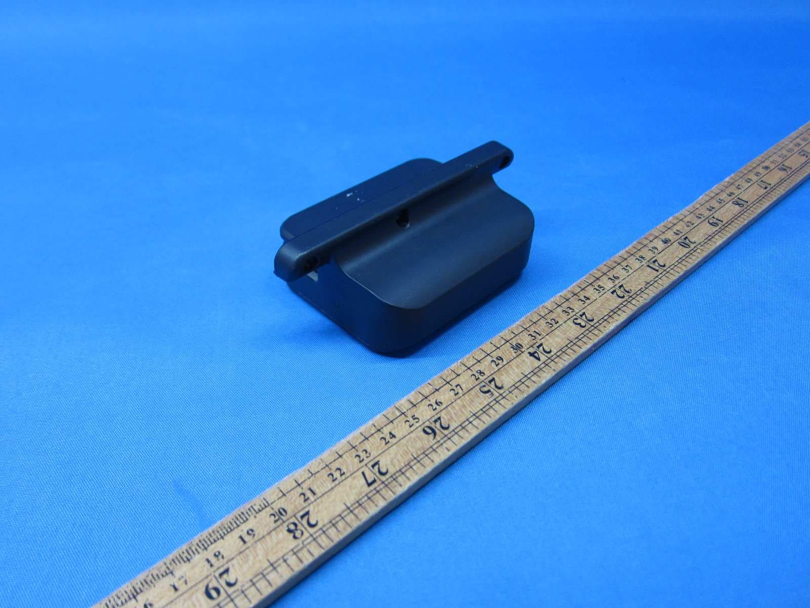
2AB7X-CHB2D
Jul 10, 2021Toast Direct Attached
Equipment Class
DXX - Part 15 Low Power Communication Device Transmitter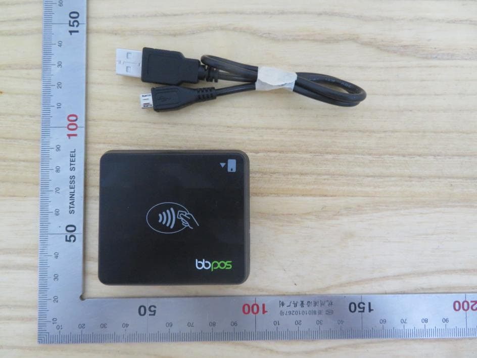
2AB7X-CHB28
Jul 07, 2021Chipper 2X BT
Equipment Class
DTS - Digital Transmission System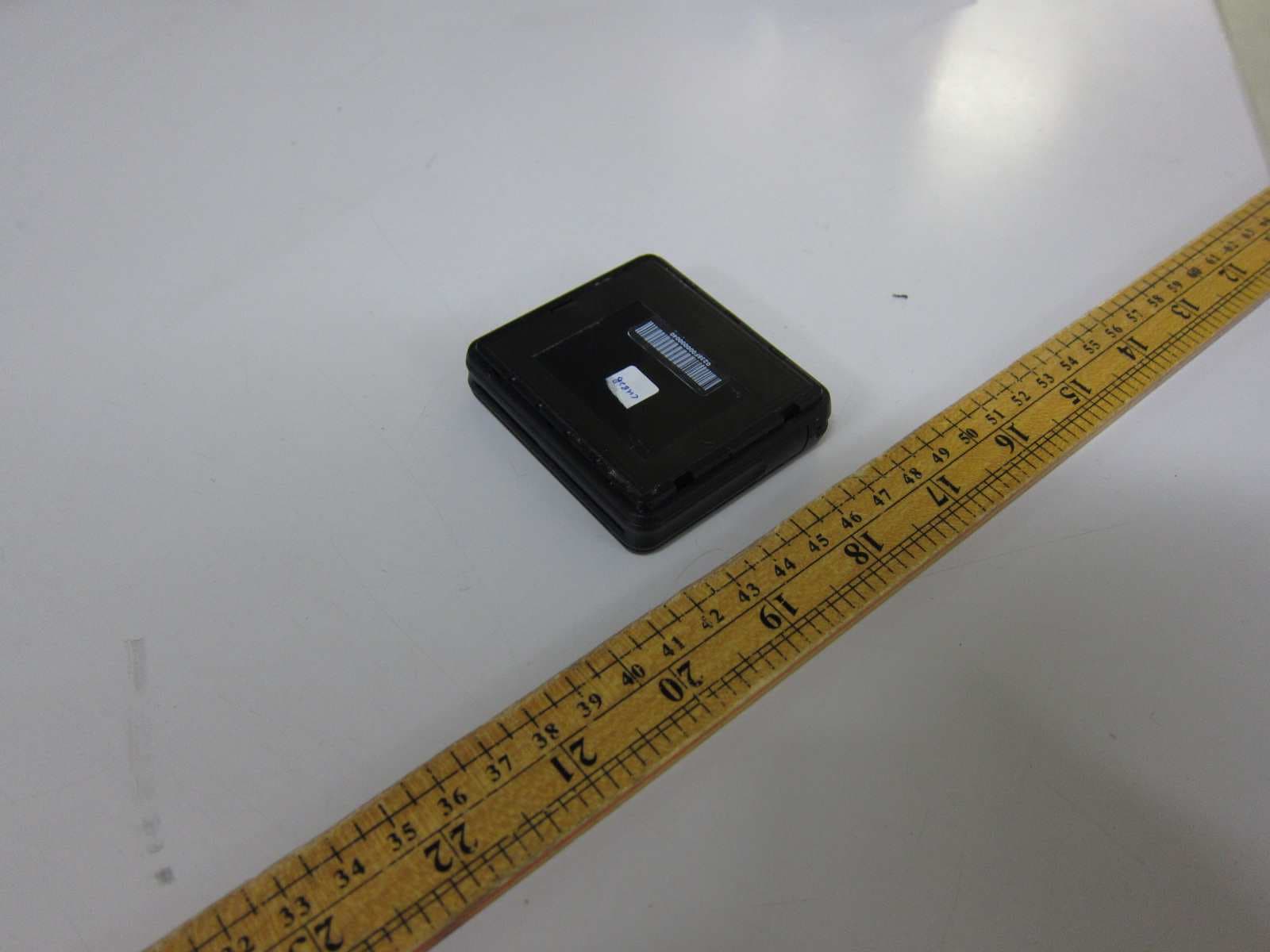
2AB7X-CHB2B
Jun 26, 2021Toast Chipper 2X BT
Equipment Class
DXX - Part 15 Low Power Communication Device Transmitter