2AB7YVDW24DRTLWiFi Module
Viper Design, LLC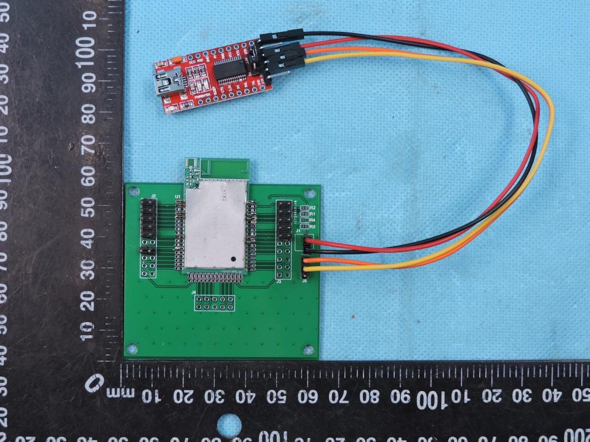
Click to zoom
Application Details
- Equipment Class
- DTS - Digital Transmission System
- Date of Grant
- Jan 07, 2020
- Application Purpose
- Original Equipment
- Date of Application
- Jan 07, 2020
- Equipment Note
- WiFi Module
- Frequency Range
- 2412.00000000 - 2462.00000000
- Company
- Viper Design, LLC
- Country
- United States
Documents & Files
Document Text
Text extracted from the exhibit documents filed with the FCC. Open a document above to read the original.
Users Manual
VDWIFI-RTL Features 2.4Ghz - 2.5Ghz Wireless Link: UART/SPI interfaces Support for both mains-powered and battery-powered devices Operating Voltage: 3.0V to 3.6V typical Temperature Range: -40C to +85C Integrated Networking Stack Integrated power management Integrated wireless Link Applications Battery Chargers Power Supplies iOT devices VDWIFI-RTL User's Guide VDWIFI-RTL Viper Design LLC 85 Cude Lane Madison, TN 37115 Phone: 615-420-6858 Version 0.1 Page 2 of 4 Note Warning: Changes or modifications to this device not expressly approved by Viper Design LLC could void the user’s authority to operate the equipment. Class B Device “NOTE: This equipment has been tested and found to comply with the limits for a Class B digital device, pursuant to Part 15 of the FCC Rules. These limits are designed to provide reasonable protection against harmful interference in a residential installation. This equipment generates, uses, and can radiate radio frequency energy and, if not installed and used in accordance with the instructions, may cause harmful interference to radio communications. However, there is no guarantee that interference will not occur in a particular installation. If this equipment does cause harmful interference to radio or television reception, which can be determined by turning the equipment off and on, the user is encouraged to try to correct the interference by one or more of the following measures: •Reorient or relocate the receiving antenna. •Increase the separation between the equipment and receiver. •Connect the equipment into an outlet on a circuit different from that to which the receiver is connected. • Consult the dealer or an experienced radio/TV technician for help.” RF Exposure This equipment complies with radiation exposure limits set forth for an uncontrolled environment. This equipment should be installed and operated with Maximum distance 20 cm between the radiator and your body. This transmitter must not be co-located or operating in conjunction with any other antenna or transmitter. Cet équipement est conforme aux limites d'exposition aux radiations dans un environnement non contrôlé. Cet équipement doit être installé et utilisé à distance minimum de 20 cm entre le radiateur et votre corps. Cet émetteur ne doit pas être co-localisées ou opérant en conjonction avec tout autre antenne ou transmetteur.” VDWIFI-RTL Version 0.1 Page 3 of 4 Low Power License-Exempt Device This device complies with Industry Canada licence-exempt RSS standard(s). Operation is subject to the following two conditions: (1) this device may not cause interference, and (2) this device must accept any interference, including interference that may cause undesired operation of the device. Le présent appareil est conforme aux CNR d'Industrie Canada applicables aux appareils radio exempts de licence. L'exploitation est autorisée aux deux conditions suivantes : (1) l'appareil ne doit pas produire de brouillage, et (2) l'utilisateur de l'appareil doit accepter tout brouillage radioélectrique subi, même si le brouillage est susceptible d'en compromettre le fonctionnement. Labels Host Device must contain the following label on the outside of the unit: Contains FCC ID: 2AB7YVDW24DRTL Contains IC: 20699-VPW24DRTL Viper Design LLC 85 Cude Lane Madison, TN 37115 Phone: 615-420-6858 VDWIFI-RTL Viper Design LLC 85 Cude Lane Madison, TN 37115 Phone: 615-420-6858 Version 0.1 Page 4 of 4 Operational Supply Voltage: 3.0V to 3.6 Operating Temperature: -40C to +85C Radio 2.4GHz: Communication Interface: UART (2 wire: TX, RX) Line interface options: Logic level, RS-232, or RS-485 Data Format: 8 data bits, 1 stop bit, configurable parity bits Baud Rate: Configurable up to 115.2k SPI (4 wire logic level: SS, SCLK, MISO, MOSI) Data Format: 8 data bits Data Rate: SPECIFICATIONS Installation Guidance The final host / module combination may also need to be evaluated against the FCC Part 15B criteria for unintentional radiators in order to be properly authorized for operation as a Part 15 digital device. The user’s manual or instruction manual for an intentional or unintentional radiator shall caution the user that changes or modifications not expressly approved by the party responsible for compliance could void the user's authority to operate the equipment. In cases where the manual is provided only in a form other than paper, such as on a computer disk or over the Internet, the information required by this section may be included in the manual in that alternative form, provided the user can reasonably be expected to have the capability to access information in that form. To ensure compliance with all non-transmitter functions the host manufacturer is responsible for ensuring compliance with the module(s) installed and fully operational. For example, if a host was previously authorized as an unintentional radiator under the Declaration of Conformity procedure without a transmitter certified module and a module is added, the host manufacturer is responsible for ensuring that the after the module is installed and operational the host continues to be compliant with the Part 15B unintentional radiator requirements.
Cover Letter(s)
C5266091_X8_Ed.1 1/1 Letter of Authorization Viper Design, LLC Company: Viper Design, LLC Address: 85 Cude Lane, Madison, TN 37115, United States Of America Product Name: WiFi Module Model Number: VDWIFI-RTL FCC Identifier: 2AB7YVDW24DRTL We authorize LGAI Technological Center S.A., Ronda de la Font del Carme, s/n, 08193 Bellaterra, Spain, to act on our behalf on all matters concerning the above named equipment. Any individual within LGAI Technological Center S.A. is authorized to act on our behalf and take action on the application. We declare that authorize LGAI Technological Center S.A., Ronda de la Font del Carme, s/n, 08193 Bellaterra, Spain, is allowed to forward all information related to the approval project to the Federal Communication Commission and to discuss any issues concerning the approval application. Any and all acts carried out by LGAI Technological Center S.A. on our behalf shall have the same effect as acts of our own. Name: Bell Kendall Brian Date: 2019/12/16 C5266091_X8_Ed.1 1/1 Title: Senior Design Partner Signature of applicant:
Cover Letter(s)
C5266091_X10_Ed.1 1/1 Viper Design, LLC Office of Engineering Technology Federal Communications Commission 7435 Oakland Mills Road Columbia, MD 21046 Date: 2019-12-16 Subject: Request for Confidentiality FCC ID: 2AB7YVDW24DRTL To Whom It May Concern, Pursuant to the provisions of Sections 0.457 and 0.459 of Commission's rules (47CFR0.457, 0.459), we are requesting the Commission to withhold the following attachment(s) as confidential document from public disclosure. Exhibits Long-Term Confidentiality Short-Term Confidentiality ID Label/Location No No Attestation Statement No No External Photos No Block Diagram Schematics Test Report No No Test Setup Photos No User’s Manual Internal Photos Parts List / Tune Up RF Exposure Info Operational Description Cover Letter(s) No No SDR Software / Security Info No Above mentioned document contains detailed system and equipment description are considered as proprietary information in operation of the equipment. The public disclosure of above documents might be harmful to our company and would give competitor an unfair advantage in the market. It is our understanding that all measurement test reports, FCC ID label format and correspondent during certification review process cannot be granted as confidential documents and those information will be available for public review once the grant of equipment authorization is issued. C5266091_X10_Ed.1 1/1 Sincerely, Signature: Name: Bell Kendall Brian Title: Senior Design Partner
Cover Letter(s)
Single Modular approval Declaration letter We ,apply Single modular approval for Product Name: WiFi Module Model: VDWIFI-RTL FCC ID: 2AB7YVDW24DRTL According to 996369 D01 Module Equip Auth Guide v01r04 and 15.212 requirement: 1) The radio elements must have the radio frequency circuitry shielded. Physical components and tuning capacitor(s) may be located external to the shield, but must beon the module assembly; Answer :Yes,with shielded 2)The module must have buffered modulation/data inputs to ensure that the device will comply with Part 15 requirements with any type of input signal; Answer :Yes ;All inputs to the modules are buffered through logic or microprocessor inputs. 3)The modular transmitter must have its own power supply regulation. Answer :Yes ;A low drop out regulator is used for modular power supply regulation. 4)The module must contain a permanently attached antenna, or contain a unique antenna connector, and be marketed and operated only with specific antenna(s), per Sections 15.203, 15.204(b), 15.204(c), 15.212(a), 2.929(b); Answer :Yes ;Device is equipped with Integral antenna. (5)The module must demonstrate compliance in a stand-alone configuration; Answer :Yes,distance between modular and all AEs are longer than 20cm ,refer to setup photo. (6) The module must be labelled with its permanently affixed FCC ID label, or use an electronic display (See KDB Publication 784748 about labelling requirements); Answer :Yes ;The modular has a permanent fixed label, and below statement was listed in the User Manual;The host device must be labeled to display the FCCID of the module Contains FCC ID: 2AB7YVDW24DRTL (7)The module must comply with all specific rules applicable to the transmitter including all the conditions provided in the integration instructions by the grantee; Answer :Yes ;The module comply with all specific rules applicable to the transmitter including all the conditions provided in the integration instructions by the grantee, Refer to test report and user manual . (8)The module must comply with RF exposure requirements Answer :Yes ;Transmitter meets MPE calculation of 47 CFR 1.1307 . Refer to MPEReports and Refer to modular installation manual Date 2019-12-18 Signature Name: Bell Kendall Brian Title: Senior Design Partner Company: Viper Design, LLC Address: 85 Cude Lane, Madison, TN 37115, United States Of America
External Photos
Page 1 of 2 Report No.: STS1911294 APPENDIX-PHOTOGRAPHS OF EUT CONSTRUCTIONAL DETAILS FCC ID: 2AB7YVDW24DRTL IC: 20699-VPW24DRTL Model: VDWIFI-RTL Photo 1 Photo 2 WIFI Antenna Page 2 of 2 Report No.: STS1911294 Photo 3
ID Label/Location Info
FCC Label Size: 10*20mm, used paster. PMN: WiFi Module HVIN: VDWIFI-RTL FCC ID: 2AB7YVDW24DRTL IC: 20699-VPW24DRTL
Internal Photos
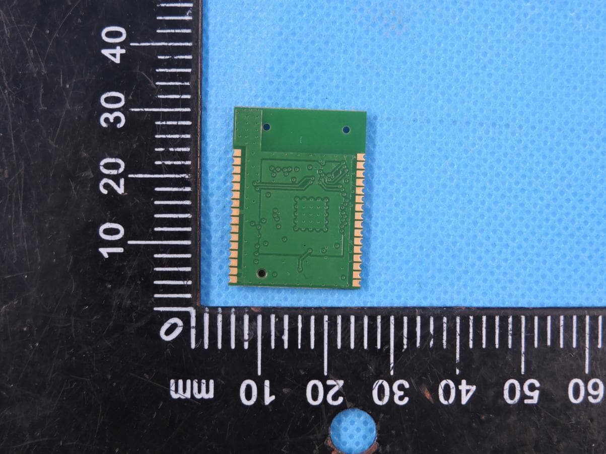
Page 1 of 1 Report No.: STS1911294 APPENDIX-PHOTOGRAPHS OF EUT CONSTRUCTIONAL DETAILS FCC ID: 2AB7YVDW24DRTL IC: 20699-VPW24DRTL Model: VDWIFI-RTL Photo 1 Photo 2
RF Exposure Info
RF Exposure Report FCC ID: 2AB7YVDW24DRTL RF Exposure Measurement The limit for Maximum Permissible Exposure (MPE) specified in FCC 1.1310 is followed. The gain of the antennas used in the product is extracted from the Antenna data sheets provided and also the maximum total power input to the antenna is measured. Through the Friis transmission formula and the maximum gain of the antenna, we can calculate the distance, away from the product, where the limit of MPE is reached. Although the Friis Transmission formula is far field assumption, the calculated result of that is an over-prediction for near field power density. It is taken as worst case to specify the safety range. RF Exposure Limit According to FCC 1.1310: The criteria listed in the following table shall be used to evaluate the environmental impact of the human exposure to radio-frequency (RF) radiation as specified in 1.1307 (b) Limits for Maximum Permissible Exposure (MPE) F= Frequency in MHz Frequency Range (MHz) Electric Field Strength (V/m) Magnetic Field Strength (A/m) Power Density (mW/cm²) Limits for Occupational / controlled Exposures 300 - 1500 -- -- F/300 1500 – 100000 -- -- 5.0 Limits for General population / Uncontrolled Exposure 300 - 1500 -- -- F/1500 1500 – 100000 -- -- 1.0 Friss Formula Friss Transmission Formula: Pd = (Pout * G) / (4*pi*r²) Where Pd = power density in mW/cm² Pout = output power to antenna in mW G = gain of antenna in linear scale Pi = 3.1416 R = Distance between observation point and the center of radiator in cm If we know the maximum gain of the antenna and the total output power to the antenna, through calculation, we will know MPE value at distance 20cm. EUT Operation condition EUT was enabled to transmit and receive at lowest, middle and highest channels. Classification The antenna of this product, under normal use condition, is at least 20cm away from the body of the user. Warning statement to the user for keeping at least 20cm or more separation distance from the antenna should be included in the User manual. So, this device is classified as Mobile device. WIFI Mode 802.11b/g/n20:2412-2462MHz Detector PEAK 802.11b 17±1dBm 802.11g 16±1dBm 802.11n20 16±1dBm ANT Gain (G) Antenna gain: 0dBi (gain of antenna in linear scale=1) 802.11 b12412 1863.09570.01256 1 802.11 g12412 1750.11870.00998 1 802.11 n2012412 1750.11870.00998 1 Power Density (mW/cm²) Limit (mW/cm²) ANT Gain(gain of antenna in linear scale) Protocol Channel Frequency (MHz) Output Power to Antenna (dBm) Output Power to Antenna (mW)
Test Report
Any reproduction of this document must be done in full. No single part of this document may be reproduced without permission from STS, All Test Data Presented in this report is only applicable to presented Test sample. Shenzhen STS Test Services Co., Ltd. A 1/F, Building B, Zhuoke Science Park, No.190 Chongqing Road, HepingShequ, Fuyong Sub-District,Bao’an District, Shenzhen, Guang Dong, China TEL: +86-755 3688 6288 FAX: +86-755 3688 6277 E-mail:[email protected] S RADIO TEST REPORT Report No:STS1911294W01 Issued for Viper Design, LLC 85 Cude Lane, Madison, TN 37115, United States Of America Product Name: WiFi Module Brand Name: Viper Model Name: VDWIFI-RTL Series Model: N/A FCC ID: 2AB7YVDW24DRTL IC ID: 20699-VPW24DRTL Test Standard: FCC Part 15.247 RSS-247 Issue 2, February 2017 S T L A B S Page 2 of 68 Report No.:STS1911294W01 TEST RESULT CERTIFICATION Applicant’s Name ................. : Viper Design, LLC Address ................................. : 85 Cude Lane, Madison, TN 37115, United States Of America Manufacture's Name ............ : Viper Design, LLC Address ................................. : 85 Cude Lane, Madison, TN 37115, United States Of America Product Description Product Name ........................ : WiFi Module Brand Name ........................... : Viper Model Name .......................... : VDWIFI-RTL Series Model .......................... : N/A Test Standards ..................... : FCC Part15.247 RSS-247 Issue 2, February 2017 Test Procedure........................: ANSI C63.10-2013 This device described above has been tested by STS, the test results show that the equipment under test (EUT) is in compliance with the FCC/IC requirements. And it is applicable only to the tested sample identified in the report. This report shall not be reproduced except in full, without the written approval of STS, this document only be altered or revised by STS, personal only, and shall be noted in the revision of the document. Date of Test ........................................... : Date (s) of performance of tests ............. : 04 Nov. 2019 ~ 06 Nov. 2019 Date of Issue .......................................... : 07 Nov. 2019 Test Result .............................................. : Pass Testing Engineer : (Chris Chen) Technical Manager : (Sunday Hu) Authorized Signatory : (Vita Li) Page 3 of 68 Report No.:STS1911294W01 Table of Contents Page 1. SUMMARY OF TEST RESULTS 6 1.1 TEST FACTORY 7 1.2 MEASUREMENT UNCERTAINTY 7 2. GENERAL INFORMATION 8 2.1 GENERAL DESCRIPTION OF THE EUT 8 2.2 DESCRIPTION OF THE TEST MODES 10 2.3 BLOCK DIGRAM SHOWING THE CONFIGURATION OF SYSTEM TESTED 11 2.4 DESCRIPTION OF NECESSARY ACCESSORIES AND SUPPORT UNITS 12 2.5 EQUIPMENTS LISTS 13 3. EMC EMISSION TEST 14 3.1 CONDUCTED EMISSION MEASUREMENT 14 3.2 RADIATED EMISSION MEASUREMENT 18 4.CONDUCTED SPURIOUS & BAND EDGE EMISSION 30 4.1 LIMIT 30 4.2 TEST PROCEDURE 30 4.3 DEVIATION FROM STANDARD 30 4.4 TEST SETUP 30 4.5 EUT OPERATION CONDITIONS 30 4.6 TEST RESULTS 31 5. POWER SPECTRAL DENSITY TEST 43 5.1 LIMIT 43 5.2 TEST PROCEDURE 43 5.3 DEVIATION FROM STANDARD 43 5.4 TEST SETUP 43 5.5 EUT OPERATION CONDITIONS 43 5.6 TEST RESULTS 44 6. BANDWIDTH TEST 50 6.1 LIMIT 50 RSS-GEN CLAUSE 6.7 50 6.2 TEST PROCEDURE 50 6.3 DEVIATION FROM STANDARD 50 6.4 TEST SETUP 50 6.5 EUT OPERATION CONDITIONS 50 Page 4 of 68 Report No.:STS1911294W01 Table of Contents Page 6.6 TEST RESULTS 51 7. PEAK OUTPUT POWER TEST 63 7.1 LIMIT 63 7.2 TEST PROCEDURE 63 CHANNEL BANDWIDTH. 63 7.3 DEVIATION FROM STANDARD 64 7.4 TEST SETUP 64 7.5 EUT OPERATION CONDITIONS 64 7.6 TEST RESULTS 65 8. ANTENNA REQUIREMENT 66 8.1 STANDARD REQUIREMENT 66 8.2 EUT ANTENNA 66 9.FREQUENCY STABILITY 67 9.1 LIMITS OF FREQUENCY STABILITY MEASUREMENT 67 9.2 TEST PROCEDURE 67 9.3 TEST RESULT 67 APPENDIX-PHOTOS OF TEST SETUP 68 Page 5 of 68 Report No.:STS1911294W01 Revision History Rev. Issue Date Report No. Effect Page Contents 00 07 Nov. 2019 STS1911294W01 ALL Initial Issue Page 6 of 68 Report No.:STS1911294W01 1. SUMMARY OF TEST RESULTS Test procedures according to the technical standards: KDB 558074 D01 15.247 Meas Guidance v05r02 FCC Part 15.247,Subpart C RSS-247 Issue 2 Standard Section Test Item Judgment Remark 15.207 RSS-Gen Issue 5 April 2018 Conducted Emission PASS 15.247 (a)(2) 6dB Bandwidth PASS 1RSS-GEN clause 6.7 99% Bandwidth PASS 15.247 (b)(3) RSS-247 Issue 2, February 2017 (5.4) Output Power PASS 15.247 (c) RSS-247 Issue 2, February 2017 (5.5) Radiated Spurious Emission PASS 15.247 (d) RSS-247 Issue 2, February 2017 (5.5) Conducted Spurious & Band Edge Emission PASS 15.247 (e) RSS-247 Issue 2, February 2017 Power Spectral Density PASS 15.205 Restricted Band Edge Emission PASS Part 15.247(d)/part 15.209(a) RSS-247 Issue 2, February 2017 Band Edge Emission PASS 15.203 RSS-Gen Issue 5 April 2018 Antenna Requirement PASS RSS-Gen Issue 5 April 2018 Frequency Stability PASS NOTE: (1)” N/A” denotes test is not applicable in this Test Report (2)all tests are according to ANSI C63.10-2013 . Page 7 of 68 Report No.:STS1911294W01 1.1 TEST FACTORY SHENZHEN STS TEST SERVICES CO., LTD Add. : A 1/F, Building B, Zhuoke Science Park, No.190 Chongqing Road, HepingShequ, Fuyong Sub-District,Bao’an District, Shenzhen, Guang Dong, China FCC test Firm Registration Number: 625569 IC test Firm Registration Number: 12108A A2LA Certificate No.: 4338.01 1.2 MEASUREMENT UNCERTAINTY The reported uncertainty of measurement y ±U, where expended uncertainty U is based on a standard uncertainty multiplied by a coverage factor of k=2, providing a level of confidence of approximately 95 %. No. Item Uncertainty 1 RF output power, conducted ±0.68dB 2 Unwanted Emissions, conducted ±2.988dB 3 All emissions, radiated 30-1GHz ±6.7dB 4 All emissions, radiated 1G-6GHz ±5.5dB 5 All emissions, radiated>6G ±5.8dB 6 Conducted Emission (9KHz-150KHz) ±4.43dB 7 Conducted Emission (150KHz-30MHz) ±5dB Page 8 of 68 Report No.:STS1911294W01 2. GENERAL INFORMATION 2.1 GENERAL DESCRIPTION OF THE EUT…
Text truncated - open the document above for the full version.
Test Setup Photos
Page 1 of 2 FCC ID: 2AB7YVDW24DRTL IC ID: 20699-VPW24DRTL DTS Setup photo Model name: VDWIFI-RTL DTS conduction DTS radiation L Page 2 of 2 FCC ID: 2AB7YVDW24DRTL IC ID: 20699-VPW24DRTL DTS radiation H
Contact Information
Applicant
Brian Kendall Bell(Senior Design Partner)
Technical Contact
Non-Technical Contact
Shenzhen STS Test Services Co., Ltd.Bovey Yang
[email protected]86-0755 36886288
Test Firm
SHENZHEN STS TEST SERVICES CO.,LTD.Bovey Yang
[email protected]+86 755-36886288
Technical Specifications
| # | Rule Parts | Frequency Range | Power Output |
|---|---|---|---|
| 1 | 15C | 2.41 GHz - 2.46 GHz | 54.58 mW |
Other Applications from Viper Design, LLC
2AB7YVDWIFIRT3
Apr 13, 2023WiFi Module
Equipment Class
DTS - Digital Transmission System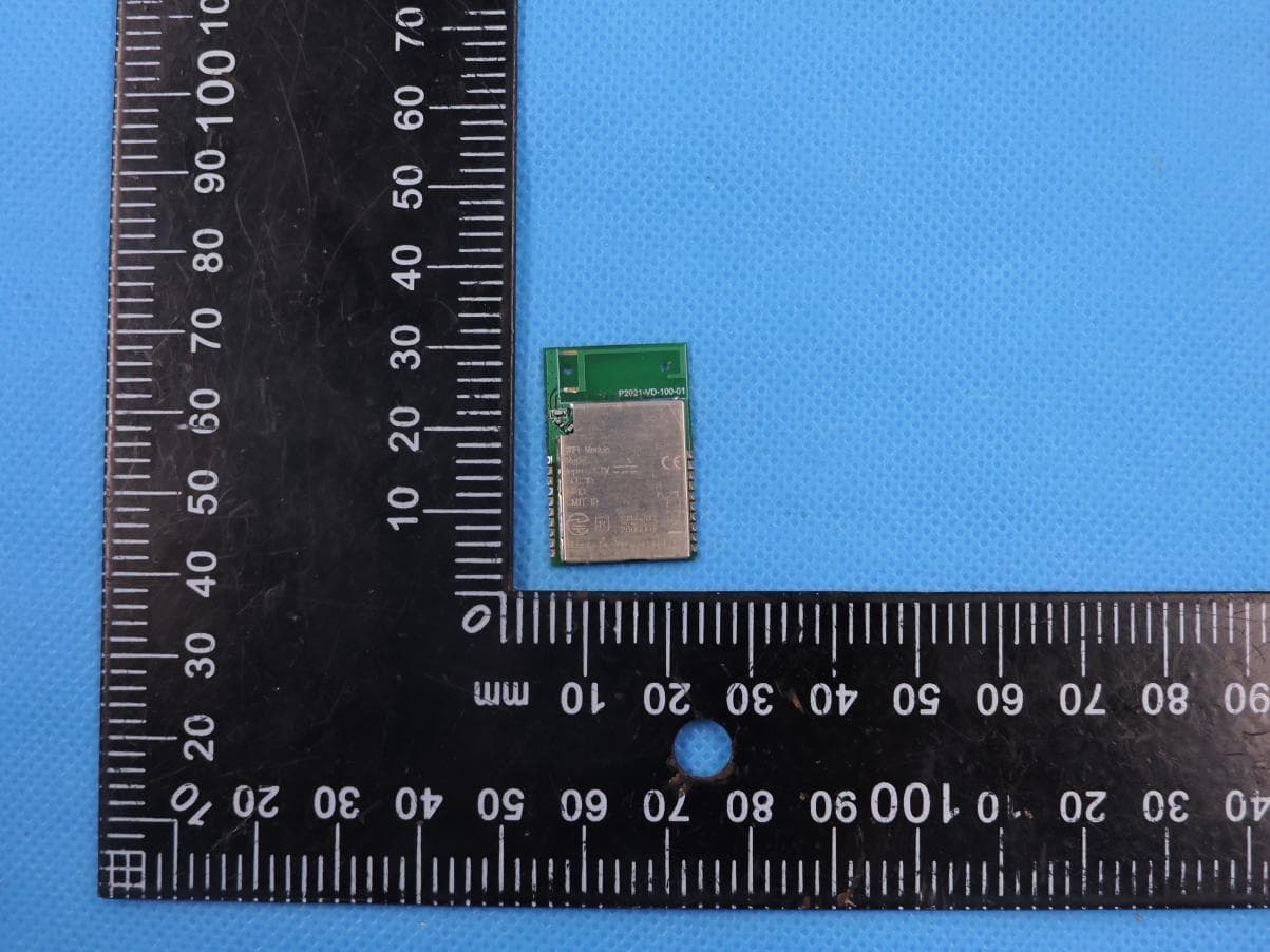
2AB7YVDWIFIRT2
Nov 07, 2022WiFi Module
Equipment Class
DTS - Digital Transmission System
2AB7YVDW24DRTH
Nov 29, 2020WiFi Module
Equipment Class
DTS - Digital Transmission System