2AB8I-RE4Transceiver for Utility Meters
Next Meters Global, LLC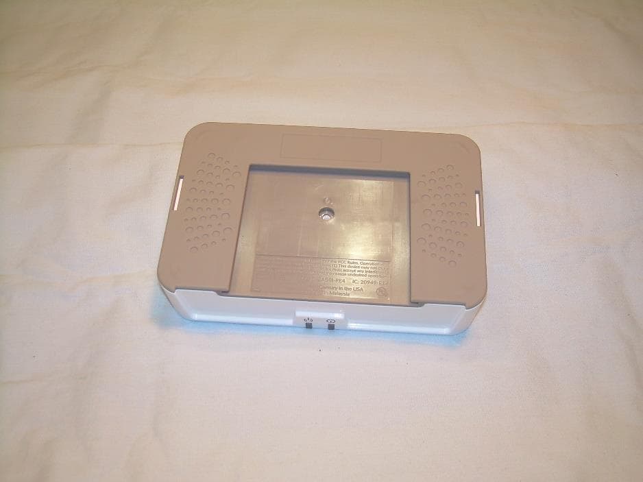
Click to zoom
Application Details
- Equipment Class
- DTS - Digital Transmission System
- Date of Grant
- Jul 29, 2021
- Application Purpose
- Original Equipment
- Date of Application
- Jul 29, 2021
- Equipment Note
- Transceiver for Utility Meters
- Frequency Range
- 2402.00000000 - 2480.00000000
- Company
- Next Meters Global, LLC
- Country
- United States
Documents & Files
Document Text
Text extracted from the exhibit documents filed with the FCC. Open a document above to read the original.
Users Manual
[email protected] www.nextcenturymeters.com V. 052521 RE4 Repeater NextCentury Connect™ Wireless Network Repeater Operation and Installation Guide 1| Product Overview The NextCentury RE4 Repeater is an easy to use, full featured device that receives signals from Transceivers and routes the data to the Gateway. The Repeater increases coverage by amplifying and repeating signals in the network. The RE4 Repeater has the longest range in its class with LED light indicators allowing for immediate verification of signal delivery during setup and maintenance. The RE4 is a drop-in replacement for the previous RE201 Repeater model and is compatible with all NextCentury radio devices. 2| Technical Specifications 2.1 – Certifications FCC: 2AB8I-RE4 IC: 20949-RE4 2.2 – Wireless ● Two-way NextCentury RF Connect™ ● 902-928 MHz Unlicensed Band 2.5 – Power Requirements ● 120/240 VAC power supply (included) 2.6 – Dimensions: ● 5.7” x 4.6” x 1.7” (145mm x 117mm x 44mm) 2.7 – Operation Environment: ● -20°C to 60°C (-4°F to 140°F ) ● Indoor or NEMA rated enclosure required 3| Device Compatibility The RE4 Repeater is compatible with all NextCentury end devices and Gateways. It is a drop-in replacement for the previous RE201 Repeater model. 3.1 – Transceiver Compatibility ● TR201 Transceiver ● TR4 Transceiver ● RR301-TR Remote Reader (with Radio) ● RR4 Remote Reader 3.2 – Gateway Compatibility ● GW201 LCD Gateway (Legacy) ● GW301 Cellular Gateway ● GW4 Cellular Gateway 4| Network Layout The Repeater can be installed in any location within RF range and will automatically be integrated into the wireless network by the Gateway and other nearby Repeaters. Where possible, select locations: ● Away from immediate obstructions ● Not directly mounted on metal beams or floor decking ● Mounted as high as possible 5| In-Field Installation 5.1 –Mounting Plate ● Adhesive backing provided to aid in installation, use of screws recommended ● Attach the mounting plate to the wall surface using the included sheetrock anchors and screws 5.2 – Power Supply ● Plug in the included 15v power supply to the Repeater and a standard 120v receptacle Note: GFCI receptacles can nuisance trip when in close proximity to any RF transmitting device – use the full length of the power supply cord and install the RE4 at least 3’ from a GFCI receptacle. [email protected] www.nextcenturymeters.com V. 052521 6| Programming & Verification 6.1 – Serial Number Scan the barcode using the NCSS Mobile App or using a barcode scanner into the NextCentury website. 6.2 – Verify Communication The Test Connect button can be pressed to verify communication with the Gateway. Two green blinks indicate that the Repeater has established two-way communication. 10| Television and Radio Interference NOTE: This equipment has been tested and found to comply with the limits for a Class B digital device, pursuant to part 15 of the FCC Rules. These limits are designed to provide reasonable protection against harmful interference in a residential installation. This equipment generates, uses and can radiate radio frequency energy and, if not installed and used in accordance with the instructions, may cause harmful interference to radio communications. However, there is no guarantee that interference will not occur in a particular installation. If this equipment does cause harmful interference to radio or television reception, which can be determined by turning the equipment off and on, the user is encouraged to try to correct the interference by one or more of the following measures: —Reorient or relocate the receiving antenna. —Increase the separation between the equipment and receiver. —Connect the equipment into an outlet on a circuit different from that to which the receiver is connected. —Consult the dealer or an experienced radio/TV technician for help. The FCC requires the user to be notified that any changes or modifications made to this device that are not expressly approved by Company Name may void the user’s authority to operate the equipment. Radiation Exposure Statement: This equipment complies with FCC radiation exposure limits set forth for an uncontrolled environment. This equipment should be installed and operated with minimum distance 20cm between the radiator & your body. As per 47 CFR §15.19 (All other devices shall bear the following statement in a conspicuous location on the device: This device complies with part 15 of the FCC Rules. Operation is subject to the following two conditions: (1) This device may not cause harmful interference, and (2) this device must accept any interference received, including interference that may cause undesired operation. As per 47 CFR §15.21 The user’s manual or instruction manual for an intentional or unintentional radiator shall caution the user that changes or modifications not expressly approved by the party responsible for compliance could void the user's authority to operate the equipment. In cases where the manual is provided only in a form other than paper, such as on a computer disk or over the Internet, the information required by this section may be included in the manual in that alternative form, provided the user can reasonably be expected to have the capability to access information in that form. ISED Statement This radio transmitter (identify the device by certification number) has been approved by Industry Canada to operate with the antenna types listed below with the maximum permissible gain indicated. Antenna types not included in this list, having a gain greater than the maximum gain indicated for that type, are strictly prohibited for use with this device. Immediately following the above notice, the manufacturer shall provide a list of all antenna types approved for use with the transmitter, indicating the maximum permissible antenna gain (in dBi). 8.4 User Manual Notice for Licence-Exempt Radio Apparatus User manuals for license-exempt radio apparatus shall contain the following te…
Text truncated - open the document above for the full version.
Cover Letter(s)
Authority to Act as Agent FCC 21-Jun-2021 Federal Communications Commission Authorization and Evaluation Division 1435 Oakland Mills Road Columbia, MD 21046 SUBJECT: FCC Application for FCC ID: 2AB8I-RE4 To Whom It May Concern: We, the undersigned, hereby authorize Jason Stewart of VPI Laboratories at 313 W. 12800 S,. Suite 311, Draper UT 84020 to act as our agent and on our behalf, to apply to the Federal Communications Commission on our equipment. Any and all acts carried out by VPI Laboratories on our behalf shall have the same effect as acts of our own. This is to advise that we are in full compliance with the Anti- Drug Abuse Act. We, the applicant, are not subject to a denial of federal benefits pursuant to Section 5301 of the Anti-Drug Act of 1988, 21 USC853a, and no party to the application is subject to a denial of federal benefits pursuant to that section. Regards, By: Adam K. Paul Title: Vice President & Executive Engineer On behalf of: NextCentury Submetering Solutions, LLC.
External Photos
313 West 12800 South, Suite 311, Draper, UT 84020 • (801) 260-4040 RE4_ExtPho.docx Page 1 of 3 PROPRIETARY External Photographs Photograph 1 – Front View of the EUT Photograph 2 – Side 1 View 313 West 12800 South, Suite 311, Draper, UT 84020 • (801) 260-4040 RE4_ExtPho.docx Page 2 of 3 PROPRIETARY Photograph 3 – Back View of the EUT Photograph 4 – Side 2 View 313 West 12800 South, Suite 311, Draper, UT 84020 • (801) 260-4040 RE4_ExtPho.docx Page 3 of 3 PROPRIETARY Photograph 5 – Top View of the EUT Photograph 6 – Bottom View of the EUT
Internal Photos
313 West 12800 South, Suite 311, Draper, UT 84020 • (801) 260-4040 RE4_IntPho.docx Page 1 of 3 PROPRIETARY Internal Photographs Photograph 1 – Front View of the Device RF Shield 902-928 MHz Antennas BLE Antenna 313 West 12800 South, Suite 311, Draper, UT 84020 • (801) 260-4040 RE4_IntPho.docx Page 2 of 3 PROPRIETARY Photograph 2 – Back View of the Device 313 West 12800 South, Suite 311, Draper, UT 84020 • (801) 260-4040 RE4_IntPho.docx Page 3 of 3 PROPRIETARY Photograph 3 – View of Circuitry Under the RF Shield
RF Exposure Info
313 West 12800 South, Suite 311, Draper, UT 84020 • (801) 260-4040 RE4_MPE.docx Page 1 of 2 PROPRIETARY 47 C.F.R. Part 1, Subpart I, Section 1.1310 47 C.F.R. Part 2, Subpart J, Section 2.1091 Maximum Permissible Exposure Calculations For FCC ID: 2AB8I-RE4 EUT Device Category = General Population/Uncontrolled Exposure EUT consists of two ISM band transmitters. One operating over a range of: 2402 MHz to 2480 MHz, and one operating over a range of 910.2 MHz to 920 MHz. MPE Summary: According subpart 1.1307 (b)(1) and 2.1091 systems operating under the provisions of this section shall be operated in a manner that ensures the public is not exposed to RF energy level in excess of the communication guidelines. Limits for General Population/Uncontrolled Exposure Limits for General Population/Uncontrolled Exposure Frequency Range (MHz) Electric Field Strength (V/m) Magnetic Field Strength (A/m) Power Density (mW/cm2) Averaging Time (Minutes) 0.3-1.34 614 1.63 *(100) 30 1.34-30 824/f 2.19/f *(180/f2) 30 30-300 27.5 0.073 0.2 30 300-1500 / / f/1500 30 1500-100,000 / / 1.0 30 f = frequency in MHz; * = Plane-wave equivalent power density Calculated Formulary: Predication of MPE limit at a given distance S = power density (in appropriate units, e.g. mW/cm 2 ) R = distance to the center of radiation of the antenna (appropriate units, e.g., cm) PG = EIRP 313 West 12800 South, Suite 311, Draper, UT 84020 • (801) 260-4040 RE4_MPE.docx Page 2 of 2 PROPRIETARY MPE and Limit are calculated for this device as follows: 2.402 GHz to 2.48 GHz Frequency Band BLE Transceiver Freq Field Strength (dBuV/m) Max Antenna Gain (dBi) Max EIRP (dBm) Max EIRP (mW) Power Density at 20 cm (mW/cm2) Limit (mW) Margin (mW) 2402 98.65 0.0 3.42 2.20 0.0004 1.000 0.9996 2440 98.72 0.0 3.49 2.23 0.0004 1.000 0.9996 2480 96.69 0.0 1.46 1.40 0.0003 1.000 0.9997 910.2 MHz to 920.0 MHz Frequency Band Freq Output Power (dBm) Max Antenna Gain (dBi) Max EIRP (dBm) Max EIRP (mW) Power Density at 20 cm (mW/cm2) Limit (mW) Margin (mW) 910.2 29.87 0.0 29.87 970.51 0.193 0.607 0.414 915.0 29.57 0.0 29.57 905.73 0.180 0.610 0.430 920.0 29.32 0.0 29.32 855.07 0.170 0.613 0.443 Result: There are two transceivers in the device. They will never transmit at the same time as only one radio is configured for use in each installation. The device meets FCC MPE limit at 20 cm for General Population/Uncontrolled Exposure as specified in 47 CRF §1.1310 and §2.1091.
Test Report
313 West 12800 South, Suite 311 Draper, UT 84020 (801) 260-4040 Test Report Certification FCC ID 2AB8I-RE4 Equipment Under Test RE4 Test Report Serial No V058330_01 Dates of Test May 19 & 20, 2021 Report Issue Date May 20, 2021 Test Specifications: Applicant: FCC Part 15, Subpart C Next Century Submetering Systems, LLC P.O. Box 360 Tybee Island, GA 31328 U.S.A. 313 West 12800 South, Suite 311, Draper, UT 84020 • (801) 260-4040 V058330_01_RE4_BLE_FCC_C.docx Page 2 of 37 PROPRIETARY Certification of Engineering Report This report has been prepared by VPI Laboratories, Inc. to document compliance of the device described below with the requirements of Federal Communications Commission (FCC) Part 15, Subpart C. This report may be reproduced in full. Partial reproduction of this report may only be made with the written consent of the laboratory. The results in this report apply only to the sample tested. Applicant Next Century Submetering Systems, LLC Manufacturer Next Century Submetering Systems, LLC Brand Name Next Century Model Number RE4 FCC ID 2AB8I-RE4 On this 20 th day of May 2021, I, individually and for VPI Laboratories, Inc., certify that the statements made in this engineering report are true, complete, and correct to the best of my knowledge, and are made in good faith. Although NVLAP has accredited the VPI Laboratories, Inc. EMC testing facilities, this report must not be used to claim product certification, approval, or endorsement by NVLAP, NIST, or any agency of the federal government. VPI Laboratories, Inc. Tested by: Norman P. Hansen Reviewed by: Benjamin N. Antczak 313 West 12800 South, Suite 311, Draper, UT 84020 • (801) 260-4040 V058330_01_RE4_BLE_FCC_C.docx Page 3 of 37 PROPRIETARY Revision History Revision Description Date 01 Original Report Release May 20, 2021 313 West 12800 South, Suite 311, Draper, UT 84020 • (801) 260-4040 V058330_01_RE4_BLE_FCC_C.docx Page 4 of 37 PROPRIETARY Table of Contents 1 Client Information ................................................................................................................................. 5 1.1 Applicant ....................................................................................................................................... 5 1.2 Manufacturer ................................................................................................................................. 5 2 Equipment Under Test (EUT) ............................................................................................................... 6 2.1 Identification of EUT .................................................................................................................... 6 2.2 Description of EUT ....................................................................................................................... 6 2.3 EUT and Support Equipment ........................................................................................................ 6 2.4 Interface Ports on EUT ................................................................................................................. 7 2.5 Modification Incorporated/Special Accessories on EUT .............................................................. 7 2.6 Deviation from Test Standard ....................................................................................................... 7 3 Test Specification, Methods and Procedures ........................................................................................ 8 3.1 Test Specification .......................................................................................................................... 8 3.2 Methods & Procedures .................................................................................................................. 8 3.3 Test Procedure ............................................................................................................................ 12 4 Operation of EUT During Testing ...................................................................................................... 13 4.1 Operating Environment ............................................................................................................... 13 4.2 Operating Modes ......................................................................................................................... 13 4.3 EUT Exercise Software ............................................................................................................... 13 5 Summary of Test Results .................................................................................................................... 14 5.1 FCC Part 15, Subpart C .............................................................................................................. 14 5.2 Result .......................................................................................................................................... 14 6 Measurements, Examinations and Derived Results ............................................................................ 15 6.1 General Comments ...................................................................................................................... 15 6.2 Test Results ................................................................................................................................. 15 7 Test Procedures and Test Equipment .................................................................................................. 25 7.1 Conducted Emissions at Mains Ports .......................................................................................... 25 7.2 Radiated Emissions ..................................................................................................................... 26 7.3 Equipment Calibration ................................................................................................................ 28 7.4 Measurement Uncertainty ..................................…
Text truncated - open the document above for the full version.
Test Setup Photos
313 West 12800 South, Suite 311, Draper, UT 84020 • (801) 260-4040 RE4_Tsup.docx Page 1 of 5 PROPRIETARY Test Set Up Photographs Radiated Photograph 1: Front View Radiated Emissions, Below 1000 MHz Worst Case Configuration Photograph 2: Back View Radiated Emissions, Below 1000 MHz Worst Case Configuration 313 West 12800 South, Suite 311, Draper, UT 84020 • (801) 260-4040 RE4_Tsup.docx Page 2 of 5 PROPRIETARY Photograph 3: Front View Radiated Emissions Worst Case – Above 1000 MHz Configuration Photograph 4: Back View Radiated Emissions Worst Case – Above 1000 MHz Configuration 313 West 12800 South, Suite 311, Draper, UT 84020 • (801) 260-4040 RE4_Tsup.docx Page 3 of 5 PROPRIETARY Photograph 5: Front View Conducted Emissions Worst-Case Configuration Photograph 6: Back View Conducted Emissions Worst-Case Configuration 313 West 12800 South, Suite 311, Draper, UT 84020 • (801) 260-4040 RE4_Tsup.docx Page 4 of 5 PROPRIETARY Reference Test Set Up Photographs Photograph 7: Reference Photo of Test Setup for Emissions Below 30 MHz Photograph 8: Reference Photo of Test Setup for Emissions From 30 MHz to 1000 MHz 313 West 12800 South, Suite 311, Draper, UT 84020 • (801) 260-4040 RE4_Tsup.docx Page 5 of 5 PROPRIETARY Photograph 9: Reference Photo of Test Setup for Emissions Above 1000 MHz
Contact Information
Applicant
Brett Jepsen(Executive Engineer)
Test Firm
VPI TechnologyJason Stewart
[email protected]801-495-2310
Technical Specifications
| # | Rule Parts | Frequency Range | Power Output |
|---|---|---|---|
| 1 | 15C | 2.40 GHz - 2.48 GHz | 2.23 mW |
Other Applications from Next Meters Global, LLC
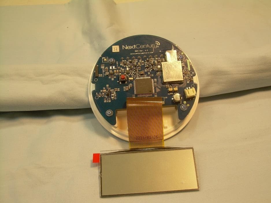
2AB8I-RR4
Apr 26, 2021Transceiver for Utility Meters
Equipment Class
DTS - Digital Transmission System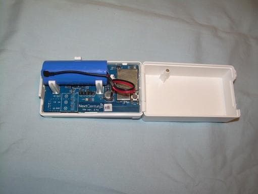
2AB8I-TR4
Feb 24, 2021Transceiver for Utility Meters
Equipment Class
DSS - Part 15 Spread Spectrum Transmitter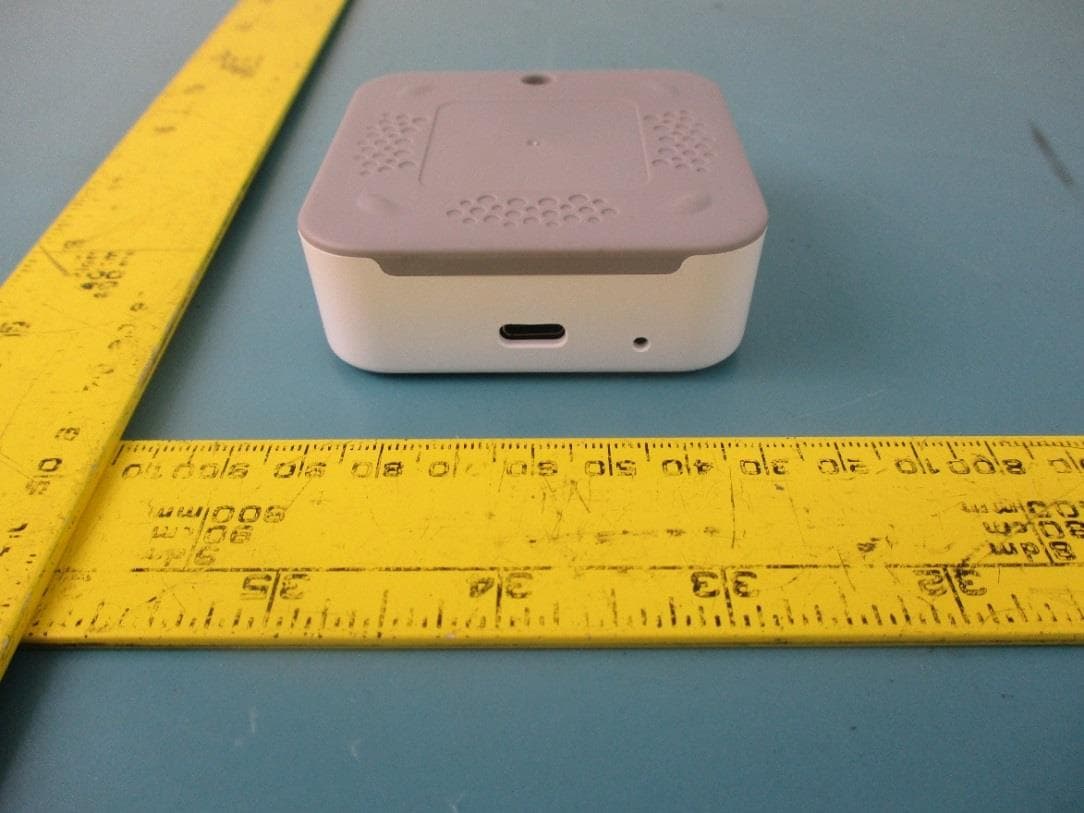
2AB8I-DC301
May 14, 2020Wireless Programming Tool
Equipment Class
DTS - Digital Transmission System
2AB8I-RR301
Feb 05, 2020Remote Reader
Equipment Class
DSS - Part 15 Spread Spectrum Transmitter